Installing Punching Dies on Machines: Step-by-Step
Installing punching dies on machines can seem daunting, but it’s crucial for precise and efficient metal fabrication. This guide covers…
Have you ever wondered why some machines run smoothly while others constantly break down? The secret often lies in the meticulous installation of drive and conveyor chains. This article explores the essential steps to ensure these chains are installed correctly, from inspecting components to fine-tuning alignment and tension. By following these guidelines, you’ll enhance the performance and longevity of your equipment. Dive in to discover practical tips that can prevent costly maintenance and ensure your machinery runs like a well-oiled machine.
The main steps for installing drive chains and conveyor chains are as follows:
Check components such as shafts, bearings, sprockets, and guards to ensure they are in good condition, free of danger or excessive wear. Verify that all bearings are installed correctly and securely.
If the chain is not new, ensure it is clean, lubricated, and free of excessive wear or hidden hazards. If the sprocket is not new, also ensure it does not have excessive wear and hidden hazards. The inspection standards for shafts and bearings should follow the product manual of the components.
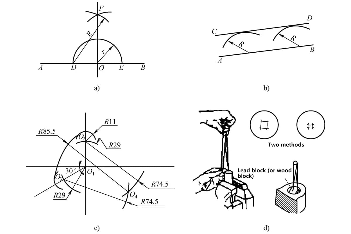
Figure 1 shows the specific operation method for axle system alignment. A mechanical bubble level can be placed directly on the shafts to carefully check the level. When multiple rows of chain sprockets are mounted on the shaft, the level can be placed horizontally on the sprocket teeth.
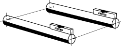
A measuring rod can be used to check the parallelism of the shafts. Parallelism should be checked first, followed by levelness. Adjust repeatedly until both parallelism and levelness meet the requirements.
For most single-row drive roller chains or conveyor chains, the alignment precision should be adjusted to within 0.050in/ft or within 0.25°. For most toothed chain drives, this limit corresponds to a chain width of up to 1in. For engineering steel chains, these limits should be appropriately relaxed.
For high-speed, high-power, multi-row roller chain drives, use the following formula to calculate the alignment limit values:
Φ=0.00133C/pn
Where
The formula also indicates that the shorter the drive center distance, the smaller the alignment limit angle should be. For toothed chains, engineering steel chains, and flat-top chains used in drives or conveyors, consult the manufacturer for the angular alignment limit values.
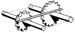
First, check for axial movement of the shaft. Before aligning the sprockets, the shaft must be fixed in the drive position, then tighten the sprocket fixing bolts for axial fixation. When there are multiple chains, ensure accurate spacing between sprockets on the shaft.
Figure 2 shows the sprocket alignment check. A straightedge can be used to check the axial alignment of two sprockets on one side of their machined surfaces. If the center distance is too large, a piano wire can replace the straightedge, and a laser device can be used to check sprocket alignment. Using a laser device is especially convenient for checking the alignment of long-center-distance conveyors.
The maximum error value for axial alignment of sprocket in roller chain drives or chain conveyors is calculated using the following formula:
δ=0.045p
Where δ is the maximum axial error (in).
Consult the manufacturer of toothed chains, engineering steel chains, and flat-top chains for the axial alignment error limits in their drives or conveyors.
For conveyor chains, carefully align the track axially with the sprockets to ensure smooth running of the chain from the track to the sprockets without scraping and hindrance. Most chain manufacturers can provide requirements for track axial alignment.
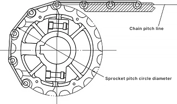
Conveyor chain tracks must also be aligned vertically with the sprockets. In most cases, the centerline of the chain hinge in the track is tangent to the pitch circle of the sprocket (see Figure 3). Most chain manufacturers can provide requirements for vertical alignment of the track.
Remove the chain from the packaging and lay it out on a bench or floor. Be careful to lay it flat without bending or twisting.
Check the chain against the manual to ensure it meets requirements. Confirm that the chain has not been damaged during transportation and storage. Similarly, if there are attachments, they should also be inspected to confirm there are no issues before installation and adjustment. For bent plate chains, pay attention to install them in the correct direction of transmission. For multi-row chain drives, check whether the attachments need to be symmetrically installed. If it is a group-matched chain drive, ensure the synchronicity and sequence horizontally.
If the chain length purchased from the factory is not the required length, it will need to be disassembled or spliced when used. Many single-row chains are made into 10ft long pieces from the factory, but this length is rarely exactly the length needed for chain transmission or conveying, so it usually needs to be shortened or spliced to lengthen.
The following are explanations of several very common methods of disassembling or connecting chains, more detailed guidance can be obtained from ACA publications or chain manufacturers.
These instructions are only for single-row roller chains, and the outer link plates of the connecting links are slip-fit. If it is a multi-row chain or the outer link plates of the connecting links are press-fit, refer to the ACA published “ANSI Roller Chain Disassembly and Connection Guide”. For other situations, consult the chain manufacturer.
1) Disassembly.
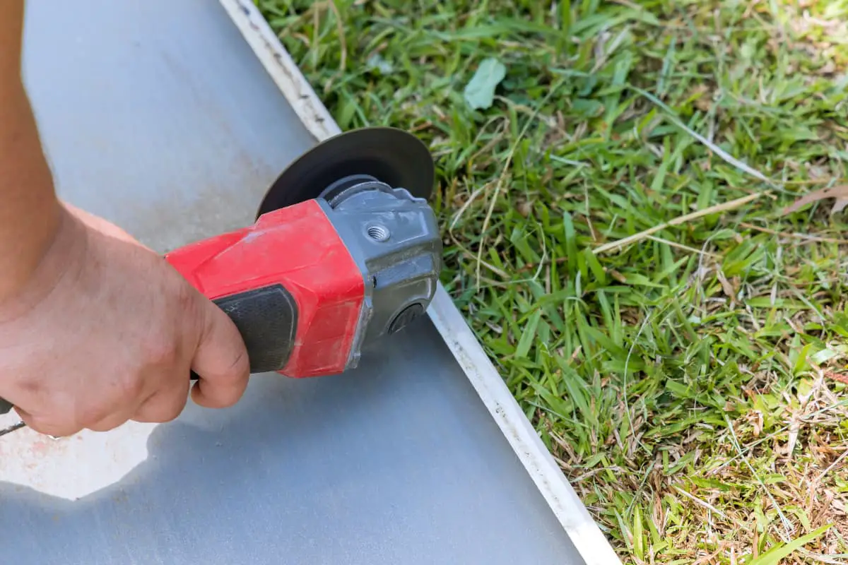
If it is a riveted chain, the rivet heads on one side of an outer link must be ground off, otherwise the pins will damage the sleeves when pressed out. If the chain has cotter pins, remove one or both from the link.
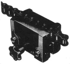
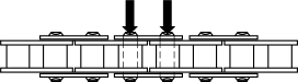
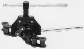
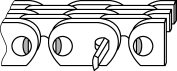
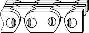
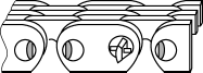
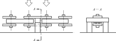
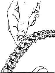
If there is available pressing equipment and appropriate tooling, the chain can be clamped with a chain clamp (see Figure 4), then the pins can be pressed out of the outer link plate (see Figure 5). If suitable pressing equipment is not available, a pin extractor (see Figure 6) can also be used to press the pins out from the outer link plate. The outer links removed from the chain generally cannot be reused.
2) Connection.
Place the ends of two chain sections opposite each other, insert the two pins of the connecting link into the sleeves of these two inner links, then install the slip-fit outer link plate on the two exposed connecting pins, and install cotter pins or spring clips, then push the connecting pins into the chain until the link plate rests against the retaining ring.
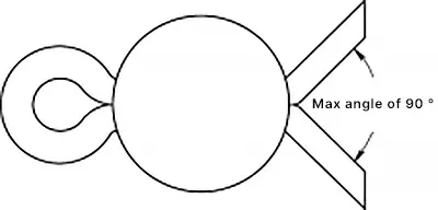
The installed spring clip should have its seamless (dead) end facing the direction of chain travel (see Figure 7). The legs of the cotter pin should not be spread apart at an angle greater than 90° (see Figure 8). A larger angle increases the risk of early failure. After connecting the chain, the connecting link must be able to bend freely.
The following instructions are only for externally guided double-pin (note: also known as roller pin type toothed chains, or commonly referred to as Hy-Vo chains) toothed chains with a single spacer joint. For other types of hinges or connectors, as well as the disassembly and assembly of internally guided toothed chains, refer to the ACA published “Toothed Chain Connection and Disassembly Guide”, or consult the chain manufacturer.
1) Disassembly.
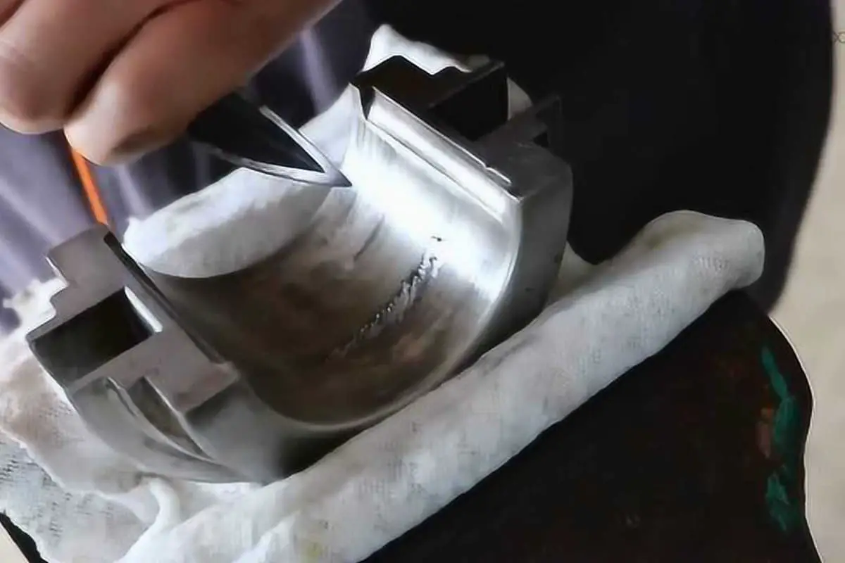
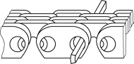
Grind off a rivet head on the outer plate (see Figure 9), because forcibly removing the pin without grinding off the rivet head will damage the chain. Then remove the long and short pins from the hinge (see Figure 10).
2) Connection.
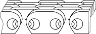
Place the ends of the chain together, ensuring the two link holes align (see Figure 11), insert the connecting long pin first (see Figure 12), then insert the short pin, making sure the convex surfaces of the two pins face each other (see Figure 13).
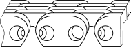
Place a spacer on the end of the long pin and lock it with a round pin or cotter pin (see Figure 14). If using a cotter pin, the legs of the cotter pin should not be spread apart at an angle greater than 90°, as too large an angle poses a risk of premature damage. Ensure that the hinge bends freely after connection.
This section only explains a few of the most common types of steel chains and connectors for engineering use. For chains or connectors not mentioned here, please refer to the publicly released information by the association: Guide to the Connection and Disassembly of Steel Chains for Engineering and Cast Chains. More information can also be obtained from chain manufacturers.
Many steel chains for engineering use are large in size, and the force applied to press the pin into the outer link plate during installation is also very great. Care must be taken when installing such chains to avoid damaging them. Because the force to install the pin is very large, a press device is usually used for chain disassembly and assembly.
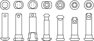
The pins of steel chains for engineering have various different styles (see Figure 15), and before disassembling the chain, it should be clear from which direction the pin should be pressed out of the chain.
1) Disassembly.
If the chain is riveted, the pin head on one side of the outer link plate must be ground off. If the chain has retaining rings and cotter pins, the retaining rings and cotter pins on the outer link plate must be removed to avoid damaging the sleeve when pressing out the pin. During disassembly, the chain plate on top of the outer link should be supported, and then the pin is pressed out of the chain plate (see Figure 16).
2) Connection.
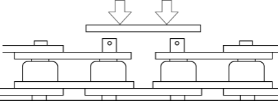
If the outer link plate and pin are a slip fit, then the installation method is the same as the previously mentioned roller chain. But if it is a press fit, the outer link plate must be installed with pressure, and the chain plate must be pressed into both pins with equal force at the same time (see Figure 17), and then place retaining rings on the connecting pins.
When the chain pitch is large, the connection of the straight plate chain for engineering is done with a single pin installation. In this case, a holed spacer should be placed under the hole of the outer link plate, carefully align the hole diameters of the two outer link plates with the connected inner link, and insert the pin as deeply as possible by hand.
Carefully align the various flat surfaces or wedge surfaces on the pin with the corresponding grooves inside the hole of the outer link plate, then press the pin into the hole of the outer link plate (see Figure 18). Repeat this process on the other side of the outer link plate, and finally install retaining rings on both connecting pins. After the connection is complete, ensure that all hinges can bend freely.
1) Disassembly.
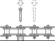
Bent plate chains usually only require pressing out one pin, as all their links are the same. If the pin is riveted, one pin head on one side of the chain should be ground off. If the chain has retaining rings and cotter pins, one side should also be removed, then place a holed spacer under the pin to be removed, and press the pin out of the chain plate (see Figure 19).
2) Connection.
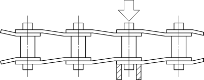
Choose one side of the chain and prop up the hole of the chain plate with a holed spacer, carefully align the hole of the chain plate with the narrow end connection hole of the next link of the chain, and insert the pin as deeply as possible by hand. Carefully align the various flat surfaces or wedge surfaces on the pin with the corresponding grooves inside the hole of the chain plate, then press the pin into the hole of the outer link plate (see Figure 20), and then install retaining rings on the connecting pins. After the connection is complete, ensure that all hinges can bend freely.
Often, the pins of flat top chains are directly used as connecting pins, because the pins are fixed by press fitting or by knurling at one end of the pin. Before disassembling or installing flat top chains, pay attention to the direction of pin installation and removal.
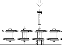
Many steel flat top chain pins are press-fitted on one side of the hinge roll. The end of the pin that is pressed into the hinge roll should also be the end from which it is removed (see Figure 21).
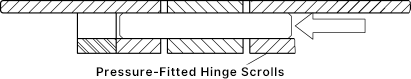
To connect steel flat top chains, check if the hinge roll is a press fit. If so, then press the straight pin from the other side of the corresponding press-fitted hinge roll into the chain (see Figure 22).
If all the hinge roll holes of the chain are the same size, then the chain’s connecting pins must have shoulders. In this case, the pin must be inserted into the chain with the smaller diameter end first (the same applies to the plastic chains mentioned later), and after the connection is complete, ensure that all hinges can bend freely.
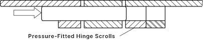
Many plastic tabletop chains are fixed in a hinge roll by a pin with one end knurled. To find the side with the knurled end of the pin, then apply pressure from the opposite side to push the pin out of the chain (see Figure 23) for disassembly.
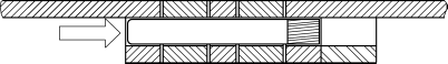
Some plastic tabletop chains have an expanded head hole on one side. Insert the knurled pin in the correct direction, then apply pressure behind the knurled end to press the pin into the chain (see Figure 24), ensuring that the hinges can bend freely after connection.
If the chain is used for a conveyor, and the structure of the conveyor allows, carriers, side plates, or crossbars can be installed on the chain first. Of course, if there are structural obstacles, then the chain must be installed on the conveyor before installing these carriers, etc.
Once the chain is connected to the appropriate length, it can be installed on the drive or conveying equipment. All installations require three basic steps:
These three steps seem very simple, but there are many details to consider in each step. Here is a summary of these details.
Many drive roller chains and toothed chains can be easily placed on the sprocket, pull the ends of the chain to wrap them around a sprocket so that the rollers are positioned in the teeth, position both ends on the sprocket and connect them into a loop. Figure 25 shows the final connection of a roller chain drive.
The installation process for larger chains is the same, but auxiliary tools are often needed during installation, such as for engineering steel chains, large-size roller chains, and very wide toothed chain installations.
The chain may also need to be hoisted into place, and the chain between two sprockets is often supported with thick wooden boards or bars, and clamps may be used to secure the chain during the final connection.
Note: When hoisting or “tensioning” for installation, be sure to carefully follow all safety warnings from the manufacturer.
Generally, conveyor chain segments should be laid out on a bench or floor for assembly, and if possible, connectors or carriers can be installed at the same time, finally threading the chain into the conveyor.
If the hanging section is right after the head shaft, it is convenient to start from there to feed the chain into the return side, carefully pulling the chain straight into the conveyor without twisting or bending, and finally pulling both ends of the chain together onto the head shaft sprocket for end-to-end connection.
As with drive chains, installing large and heavy conveyor chains usually requires auxiliary devices. Hoisting may be needed to place the chain into the conveyor, and clamps may be used to secure the chain during the final connection. For particularly large conveyor chain installations, it may be necessary to connect the chain segments while installing them onto the conveyor, and the connectors and carriers on the chain can only be installed after the chain is fully installed on the conveyor.
Pulleys and blocks, as well as “tensioning,” are also commonly used in the installation of bucket elevator chains, with the final connection of the bucket elevator chain usually made on the tail sprocket. This is because the chain tension is the lowest at this point. For large conveyors and bucket elevators with large chains, consult the chain or equipment supplier for installation issues.
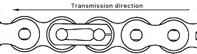
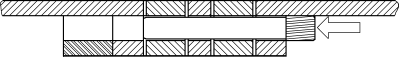
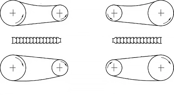
To minimize wear between the bushing and the pin, bent plate chains should be installed according to the direction of drive, with the basic concept shown in Figure 26. The principle of installing bent plate chains according to the direction of drive is that regardless of whether the small sprocket is the driver or driven, the narrow end or roller end of the chain links on the tight side should always face the small sprocket. When the roller engages and disengages from the sprocket, i.e., when the chain hinge articulates, the smaller the sprocket, the greater the articulation angle.
When the wide end of the chain link, i.e., the pin end, faces the sprocket teeth, all sliding between the pin and the bushing hole is under full load, resulting in maximum wear between the two, and the chain will stretch faster and require more frequent replacement.
When the narrow end of the chain link faces the sprocket teeth, although sliding between the pin and the bushing hole will still occur, the load between them rapidly decreases as they articulate. The entire load transfer between the sprocket teeth and the tight side of the chain goes from the roller to the bushing and then to the chain plate, resulting in minimal wear between the pin and the bushing hole, reducing the extent of chain wear and the need for replacement.
Wear elongation may be the main reason for chain replacement, so choosing the direction of drive that minimizes wear between the pin and the bushing hole is the correct direction. When the drive ratio is not 1, the narrow end or roller end of the chain links on the tight side should face the smaller sprocket with the larger turning angle. Indeed, the greater the size difference between the two sprockets, the more the wear life is increased.
Usually, the drive is for deceleration, meaning the driver sprocket is smaller and has a higher speed than the driven sprocket. However, there are also cases of speed increase drives, therefore, determining the direction of chain drive based on the driver and driven sprockets is not feasible.
Careful inspection should be carried out before starting newly installed equipment. The inspection should at least include the following items:
First, rotate the two sprockets in opposite directions so that the chain slack is concentrated on one side to form the loose and tight sides of the chain, then use a straightedge to measure the distance between the chain rollers engaged with the first tooth of both sprockets, which is the straight-line distance between the two engagement points. Then use a ruler to measure the total AC movement at the midpoint of the slack side (see Figure 27).
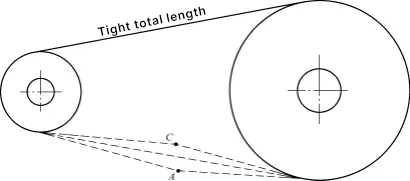
When the chain drive is arranged horizontally or at an incline angle of less than 45°, the ratio of the total measured movement to the distance between the two engagement points should be 4% to 6%. In the case of horizontal transmission, the AC sag depth is about 0.443. For large-angle inclined transmission between 45° and vertical transmission, the ratio of the total movement to the distance between the two engagement points should only be 2% to 3%.
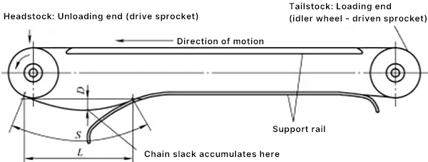
For horizontal conveying, the sag measurement is shown in Figure 28, using a straightedge to measure the distance (L) between the last roller engaged with the sprocket and the first roller of the chain on the support track, then use a ruler to measure the sag depth (D).
The sag adjustment for tensioning is recommended by the chain manufacturer. For vertical conveyors or bucket elevators, sag is generally not recommended. The initial chain tension and adjustment method are recommended by the chain manufacturer.
Install and start the lubrication system, ensure the oil reservoir is full, the oil path is clear and clean, and ensure the chain oil supply meets the design requirements.
Gently turn the drive shaft (preferably by hand) to see if the chain operation is ideal. For some large equipment, it must be started to be inspected, and during this time, ensure that all safety rules are followed to prevent injury to personnel and damage to equipment. The chain should run through the entire track for at least one complete cycle.
Confirm that the chain has passed through the entire track. Carefully check to ensure that the chain runs smoothly when meshing with the sprocket, including no scraping or obstruction in the track. It is best to let the chain run unloaded for a few hours, which can provide time for the bearings to wear in and for the lubricating oil to penetrate these working surfaces.
After the test run, check all fasteners and reinforce them as needed, and also check the chain tension and adjust as necessary.
If the chain is not transmitted inside a casing, it should be enclosed with protective covers to prevent injury from touching the moving chain and sprocket. For more information, see American National Standards, such as ASME B15.1 and ASME B20.1.
Before installing protective covers, check them for damage and potential hazards. During installation, ensure that all fasteners are not missing and connections are reliable. Also, check safety devices, such as sensors and interlocks on the equipment.