I. Basic Process Knowledge
1. Thread Tapping
Thread tapping is the cutting process of machining internal threads on parts using corresponding tools (taps and wrenches).
(1) Common Tools for Thread Tapping
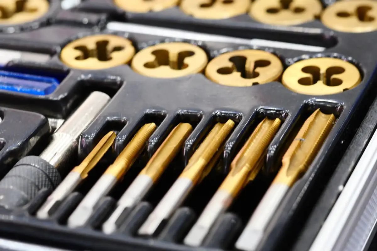
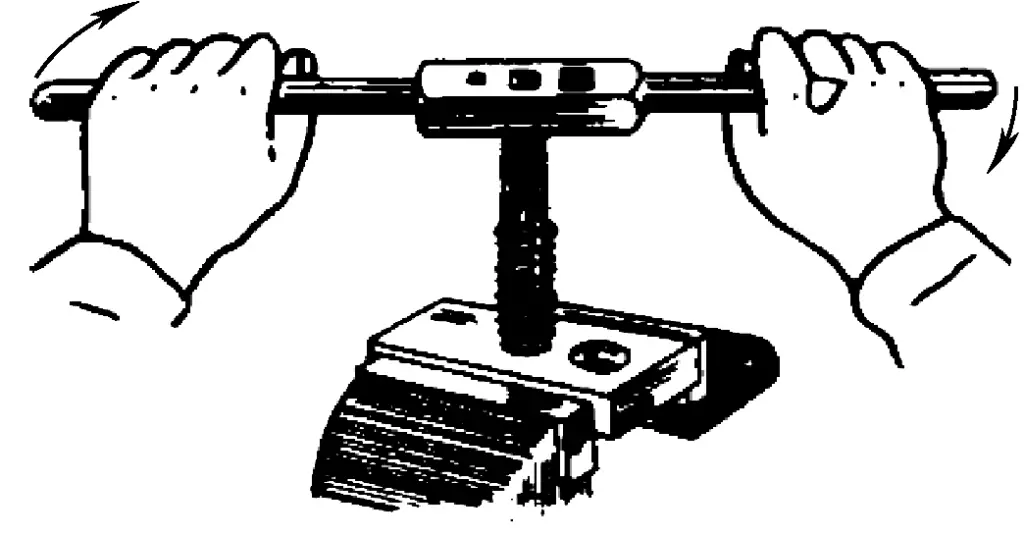
Figure 1 shows the manual thread tapping process by the fitter, and Figure 2 shows the commonly used manual thread tapping tools.
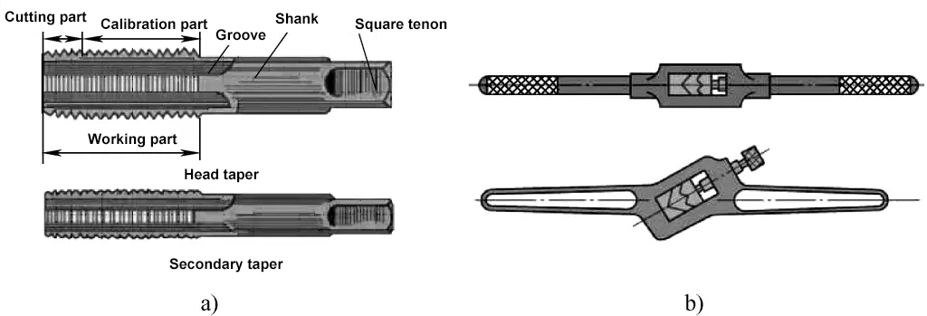
a) Tap
b) Wrench
When tapping threads, in order to reduce cutting force and improve the durability of the taps, the entire cutting amount is distributed among several taps. These taps that work together to complete the thread tapping are called a set. The tap used to start the thread tapping is called the initial tap, followed by the second tap, and lastly the third tap (commonly known as the first tap, second tap, and third tap).
Figure 3 shows the distribution of cutting amounts for a set of taps, which includes tapered distribution and columnar distribution. Generally, for taps size M6 to M24, each set contains two taps. For threads below M6 or above M24, each set contains three taps.

a) Tapered Cutting Distribution
b) Columnar Cutting Distribution
1—Initial Tap or First Rough Tap (Initial Tap)
2—Middle Tap or Second Rough Tap (Second Tap)
3—Final Tap or Finish Tap (Third Tap)
(2) Diameter and Depth of Drilled Hole (Commonly Known as Bottom Hole) Before Thread Tapping
Before thread tapping, a bottom hole for tapping is first drilled using a drill bit, and the selection of the bottom hole diameter is particularly important. Practice has shown that if the bottom hole diameter is too large, the height and depth of the machined thread will be insufficient, and the top of the thread will not be sharp; if the bottom hole diameter is too small, thread tapping will be difficult and can easily cause the tap to break.
The correct selection principle is generally based on the material of the workpiece (plastic or brittle) and the expansion amount of the hole during drilling. Even in thread tapping, ensure that there is both a gap between the tooth root of the tap and the top end of the thread form and that a complete thread form is produced.
1) Calculation of Bottom Hole Diameter Before Thread Tapping
Practice has shown that the diameter of the drill bit for drilling the bottom hole for standard threads can be determined by the following empirical formulas:
For steel and ductile materials Ddrill = D – P
For cast iron and brittle materials Ddrill = D – (1.05~1.1)P
Where Ddrill is the diameter of the bottom hole before tapping (mm); D is the major diameter of the internal thread (mm), i.e., the nominal diameter of the workpiece thread; P is the pitch (mm).
For example, when tapping M10 threads on medium carbon steel and cast iron workpieces, calculate the drill bit diameter before drilling.
Medium carbon steel belongs to ductile materials, so the drill bit diameter is
Ddrill=D-P=(10-1.5)mm=8.5mm
Cast iron belongs to brittle materials, so the drill bit diameter is
Ddrill=D-1.1P=(10-1.1×1.5)mm=8.35mm
After rounding, select a series value drill bit diameter of 8.4mm.
2) Calculation of the depth of the pre-drilled hole for tapping threads in a blind hole
As shown in Figure 4, when tapping threads in a blind hole, the smooth length depth h must be at least equal to the sum of the thread length L and the additional cutting part of the tap, because the cutting part of the tap cannot produce a complete thread. This additional length is roughly equal to 0.7 of the major diameter of the internal thread, i.e.,
h=L+0.7D

2. Die threading
Die threading is also called threading, which is the cutting process of producing external threads on a round rod using appropriate tools (die and die wrench).
(1) Die threading tools
Figure 5 shows the manual die threading process and tools.

a) Manual die threading process
b) Die wrench for threading
c) Die for threading
(2) Determining the diameter of the round rod before die threading
In the die threading process, just like in tapping, the tool (die) also exerts some extrusion on the thread part of the workpiece, hence the diameter of the round rod should be a bit smaller than the major diameter of the thread. The empirical formula is
d′=d-0.13P
In the formula, d’ is the diameter of the round rod (mm); d is the major diameter of the external thread (mm), i.e., the nominal diameter of the thread; P is the pitch (mm).
II. Basic operational skills
1. Tapping operation process
(1) Tapping steps
The steps for tapping are shown in Figure 6.
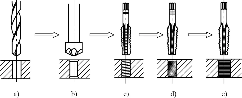
a) Drilling the bottom hole
b) Chamfering the hole entrance
c) First tap
d) Second tap
e) Third tap
(2) Key points and precautions for tapping
1) Key points for tapping
The key to tapping is the initial threading, and the operation method is shown in Figure 7. Hold the middle of the wrench with the right hand and press down, while slowly rotating the wrench with the left hand, as shown in Figure 7a. After the first tap enters 1-2 turns, visually inspect from front and back, left and right directions, or use a square to check the perpendicularity of the tap to the workpiece, as shown in Figure 7b.
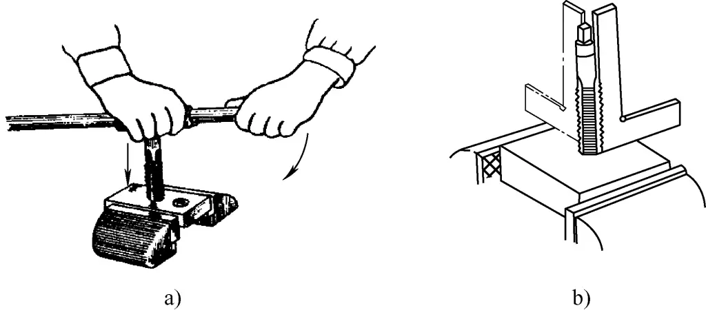
a) Initial threading
b) Checking perpendicularity
In order to ensure the verticality of the initial threading of the tapered tap, a standard nut or special guiding tool can be used, as shown in Figure 8. After the initial threading, do not apply pressure with both hands; instead, use a balanced and even rotational force to turn the tap wrench. After rotating 1/2 to 1 turn, reverse 1/4 to 1/2 turn, as shown in Figure 9. Once the tapered tap is completed, follow the sequence to switch to the second and third taper taps for threading.
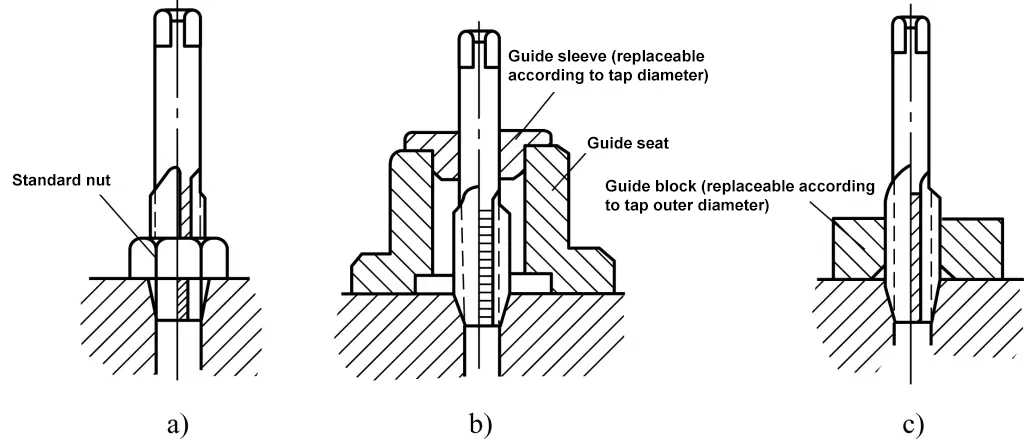
a) Guiding with a standard nut
b) Guiding with a special guide sleeve
c) Guiding with a special guide block

2) Precautions for threading
① When holding the tap with a tap wrench, the square shank of the tap should be clamped.
② When threading harder materials, if it feels very difficult, do not force turn. Instead, alternate between the initial taper and the second taper taps, threading in turns (thread a few turns with the initial taper, switch to the second taper for a few turns, then back to the initial taper, and so on).
③ During the threading process, cutting fluid should be added timely:
- When threading cast iron, machine oil is generally used for cooling and lubrication. Since cast iron soaked in kerosene will cause the hole diameter to shrink, kerosene should not be used for cooling and lubrication during tapping.
- When threading steel, it is more suitable to use diesel oil for lubrication; for aluminum alloy or pure copper, kerosene can be used for lubrication.
(3) Common problems during threading (see Table 1)
Table 1: Problems encountered in threading and cause analysis
| Problems encountered | Main cause analysis | |
| Damaged threads | Damaged thread mouth | When initial threading, the tap handler is not held steadily, repeatedly correcting the verticality of the tap to the workpiece end face, leading to damaged threads |
| Selecting too small a diameter for the threading hole bottom, making it difficult for the tap to cut, leading to a damaged thread mouth | ||
| Other partial thread damage | Forcing threading without properly aligning the tap with the previously cut threads when switching to the second or third taper taps | |
| Not reversing to remove chips as required, causing iron chips to stick to the cutting edge and damage the cut threads | ||
| When threading plastic materials, not adding cutting fluid in time leads to thermal expansion and tearing after the material is cut, causing the threads to be damaged with material sticking to the cutting edge | ||
| Misaligned threaded hole | 1) During initial threading, the tap axis is not perpendicular to the workpiece end face and not effectively corrected; 2) Uneven force applied by both hands during threading, causing misalignment when cutting in | |
| Insufficient thread depth (thread height not enough) | 1) The bottom hole diameter is selected too large; 2) The tap is worn out | |
| Tap breakage | 1) The diameter of the base hole is too small before threading; 2) Correcting or continuing threading forcibly when the tap is too skewed; 3) Chips jam the tap, but still forcefully turning the tap; 4) The cutting teeth of the tap are too dull, cutting forcefully; 5) Uneven or excessive force with both hands; 6) Material is too hard or has hard spots inside | |
2. Threading operation process
(1) Chamfer the round rod
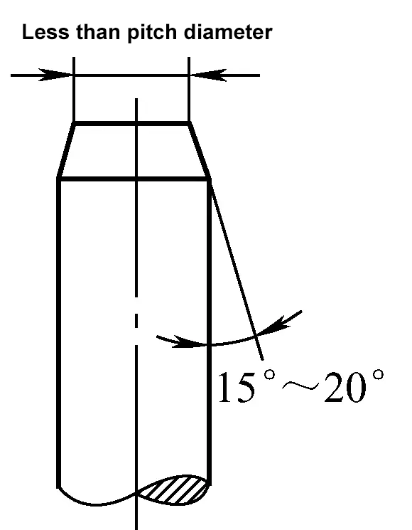
At the start of threading, to ensure the die smoothly enters the workpiece and guides correctly, the end of the round rod should be chamfered before threading. The chamfering requirements are as shown in Figure 10.
(2) Workpiece clamping
During threading, due to the large cutting torque and the cylindrical shape of the workpiece, V-shaped pads or thick soft metal linings should be used at the jaws to clamp the round rod firmly. Also, the part of the round rod to be threaded should not extend too far from the jaws.
(3) Key points for threading operation
- During the threading process, the die face should always remain perpendicular to the axis of the round rod.
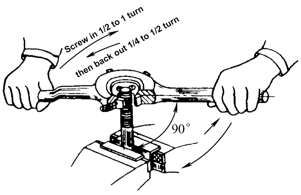
- When starting to thread, hold the middle part of the die holder with your right hand, apply pressure along the axis of the round rod, and rotate clockwise in coordination with your left hand. Alternatively, hold the handles of the die holder with both hands (holding near the middle), apply pressure, and rotate simultaneously, as shown in Figure 11.
- Once the die has cut threads into the rod, use rotational force with both hands to thread the rod out.
- During threading, cutting fluid should be applied to reduce the surface roughness of the threads and extend the life of the die. Generally, a concentrated emulsion or engine oil is used.
(4) Common problems during threading (see Table 2)
Table 2 Common problems during threading and cause analysis
| Problems | Main cause analysis |
| Damaged threads | 1) Unsteady die holder during initiation, repeatedly correcting the perpendicularity of the die face to the axis of the round rod, leading to damaged threads; 2) Selecting a round rod diameter that is too large before threading, making it difficult for the die to cut in, resulting in damaged threads |
| Skewed thread hole | 1) The die face is not perpendicular to the axis of the round rod during threading; 2) Poor rod-end chamfering, making it difficult to position the die correctly; 3) Uneven force with both hands during threading, causing skewing while cutting |
| The thread depth is not enough (thread height is not enough) | 1) The diameter of the round rod is too small; 2) The round rod is bent; 3) When adjusting the die position, the die swings up and down multiple times |

