During the fabrication of welded structural components, although a series of necessary measures are taken, residual deformation often inevitably occurs; therefore, when the residual deformation exceeds the technical requirements, measures must be taken to correct it.
Common correction methods include manual correction, mechanical correction, flame correction, and electromagnetic correction, etc.
1. Manual correction method
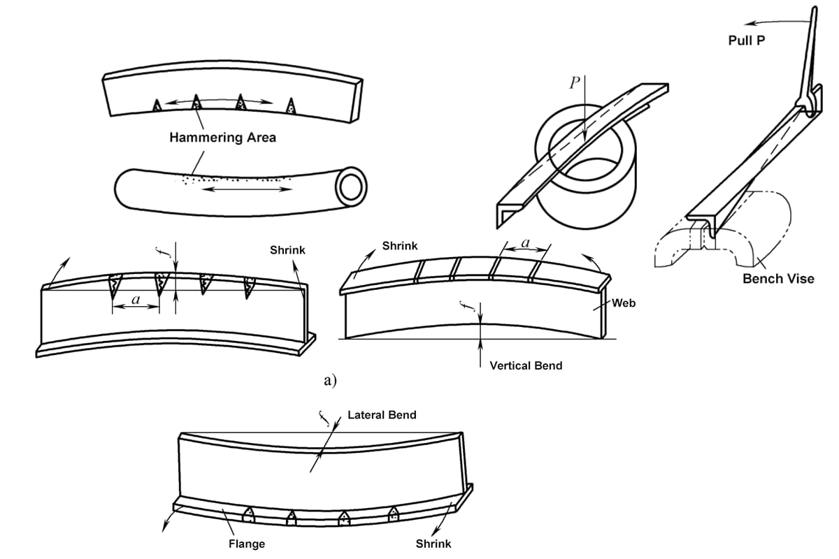
The manual correction method involves using tools such as hammers to strike the deformed parts of the weldment. This method is mainly used for bending deformation of small and simple weldments and wave deformation of thin plates.
2. Mechanical correction method
Hydraulic presses, jacks, specialized straightening machines, and hammers are commonly used. External forces are applied to cause plastic deformation in the component opposite to the direction of welding deformation, thereby neutralizing each other. Figure 9-80 shows a schematic of mechanical straightening of a bent I-beam after welding using a press or jack. The angle deformation of the I-beam flange can be corrected using the roller machine shown in Figure 9-81.

a) Press correction b) Jack correction
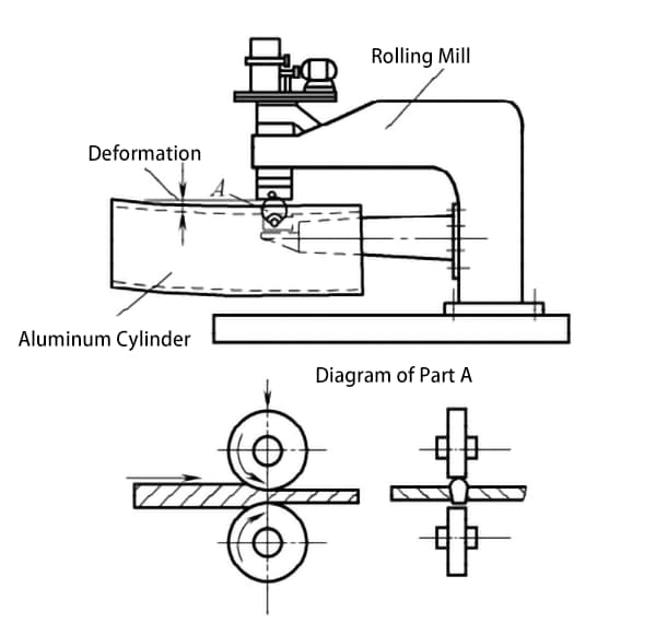
Deformation after welding is mainly caused by the shrinkage of the weld and its nearby area. If forging or rolling is performed along the weld area to achieve plastic elongation, it can compensate for the plastic deformation that occurs during welding, thus eliminating the deformation. Small welded parts with few quantities are generally forged with a hand hammer. For thin plate structures with regular welds, rolling equipment can be used to roll the weld and its nearby areas, achieving good technical and economic effects.

Figure 9-82 shows a schematic of correcting the bending deformation of an aluminum cylinder after welding using a rolling machine, where the longitudinal seam is rolled. Changing the direction of the pressure roller can also roll the circumferential weld. Rolling forging of the weld not only eliminates residual welding deformation but also eliminates residual welding stress.
Mechanical correction methods are only suitable for simple structures of medium and small welded parts.
3. Flame correction method
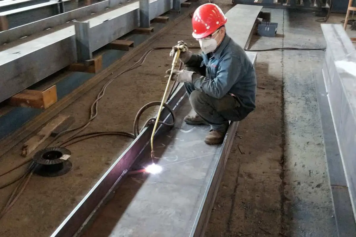
The flame correction method, also known as the heating correction method, uses a flame as a heat source to locally heat the metal, causing it to undergo compressive plastic deformation. As the metal cools, it contracts, and the deformation caused by this contraction is used to counteract the residual deformation caused by welding.
This method generally uses a gas torch and does not require specialized equipment. It is simple and convenient to operate, flexible, and can be used to correct large and complex structures.
(1) The three essentials of flame correction
There are three main factors that determine the effect of flame correction: heating position, heating temperature, and the shape of the heated area.
1) Heating position
It is the key factor for success or failure. An incorrect heating position will not only fail to correct the deformation but may even worsen the existing deformation. Therefore, the selected heating position must cause the deformation in the opposite direction to the residual deformation from welding, to counteract it.
The main reasons for bending or angular deformation are that the welds are concentrated on one side of the neutral axis of the workpiece. To correct these deformations, the heating position must be chosen on the opposite side of the neutral axis, as shown in Figure 9-83. The farther the heating position is from the neutral axis, the better the correction effect.
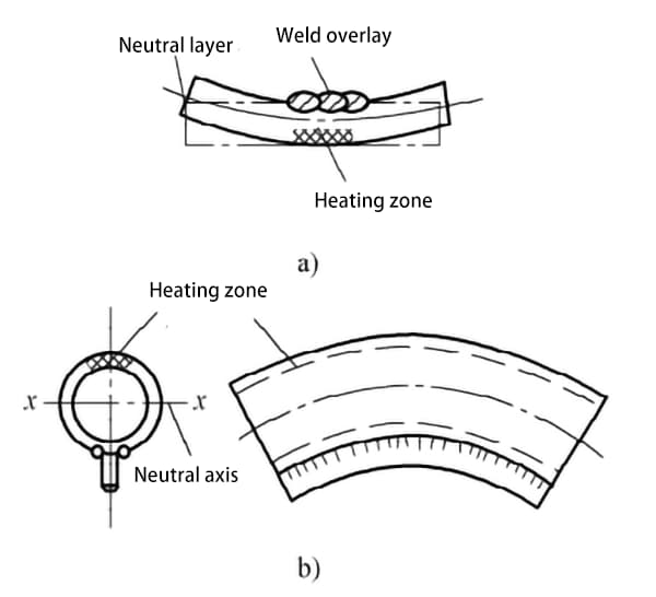
a) Angular deformation from build-up welding b) Finned tube bending deformation
2) Heating temperature
The temperature of the heated area must be higher than that of the adjacent unheated area, causing the heated metal to thermally expand and be obstructed, resulting in compressive plastic deformation. For thick carbon steel plates or welded components with high rigidity, local heating temperatures above 100°C can produce compressive plastic deformation. In production, the temperature for flame correction heating of structural steel is generally controlled between 600~800°C.
On-site temperature measurement is inconvenient, generally, the color of the heated part is observed with the eyes to estimate the approximate temperature. Table 9-13 lists the colors of the steel plate surface during the heating process and their corresponding temperatures.
Table 9-13 Colors of steel plate surface and their corresponding temperatures
| Color | Temperature (°C) |
|---|---|
| Dark Brown-Red | 550-580 |
| Brown-Red | 580-650 |
| Dark Cherry Red | 650-730 |
| Deep Cherry Red | 730-770 |
| Cherry Red | 770-800 |
| Light Cherry Red | 800-830 |
| Bright Cherry Red | 830-960 |
| Orange-Yellow | 960-1050 |
| Dark Yellow | 1050-1150 |
| Bright Yellow | 1150-1250 |
| White-Yellow | 1250-1300 |
3) The shape of the heating area.
The shapes of the heating area include dot, stripe, and triangle, as shown in Figure 9-84, with dot heating shown in Figure 9-85, line heating shown in Figure 9-86, and triangle heating shown in Figure 9-87.

a) Dot b) Stripe c) Triangle


a) Straight-through heating b) Chain heating c) Band heating

(2) Common flame correction methods
Common methods for correcting welding deformation by flame are shown in Table 9-14.
Table 9-14 Methods for correcting welding deformation by heating
| Heating method | Methods | Note |
| Dotted Heating (See Figure 9-85) | Depending on the deformation, heat can be applied at one or multiple points d=φ15 to φ30mm a=50~100mm | 1. Generally use oxyacetylene neutral flame 2. Pay attention to the properties of the material being corrected 3. Pay attention to the environmental temperature of the workplace 4. When correcting thin plates, use a wooden mallet for hammering 5. First plan the heating locations and steps according to the deformation 6. For high-strength steels that have been heat treated, the heating temperature should not exceeding its tempering temperature 7. When using water cooling in conjunction with flame correction, the steel should be cooled down until it loses its red state before pouring water 8. The heating location is usually far from the weld 9. If the subsequent process after correction is welding or gas cutting, the required amount of reverse deformation can be made during the flame correction process 10. The color corresponding to the temperature during the heating process is shown in Table 9-13 |
| Linear Heating (See Figure 9-86) | The flame moves in a straight line direction, and can also make lateral swings in the width direction, with a heating width of 0.5 to 2 times the plate thickness | |
| Triangular heating (see Figure 9-87) | On the edge of the corrected steel, heat into a triangle with the apex pointing inward | |
| Heat, water, and power are used in combination. | When heating and correcting thin plate structures, water cooling or external force can be used simultaneously to improve the correction effect |
Examples of flame correction of welding deformation are shown in Figure 9-88.

a) Lateral bending of asymmetric arch steel
b) Upward deflection of asymmetric I-beam
c) Angular deformation of butt arch joint
d) Wavy deformation of medium thin plate
(3) Test results after flame correction
Results of flame correction tests for some commonly used low-alloy steels are shown in Table 9-15.
Table 9-15 Partial test results of commonly used low-alloy structural steels after flame correction
| Steel Grade | Experimental Conclusions and Precautions |
| 14MnNb | Flame correction tests on welded fatigue beams show that flame correction has little effect on the properties of steel |
| Q345 (16Mn) | With good flame correction and hydrothermal bending plate ① performance. When the heating temperature of the hydrothermal bending plate is around 650°C, the mechanical properties are almost unaffected, and even after heating at 850~900°C, it still has sufficient strength and plasticity |
| Q390(15MnV) | Local heating correction with oxy-acetylene flame does not affect the mechanical properties of the steel |
| Q420 | Local heating correction with oxy-acetylene flame does not affect the mechanical properties of the steel |
| 14MnVTiXt | Local heating correction with oxy-acetylene flame does not affect the mechanical properties of the steel |
| 10MnPNbXt | Local correction with oxy-acetylene flame does not affect the mechanical properties of the steel |
| Q390(15MnTi) | Correction with oxy-acetylene flame can be used, and thin steel plates can also use hydrothermal bending plates |
| 08MnPXt | When correcting deformation with local flame baking, the temperature should be between 600~700°C. Because at 600~700°C, the grains begin to grow, and at 700~800°C, Widmanstätten structures appear |
| Q345 (09MnCuPTi) | The grains of the thin plate are still fine at 900°C, and Widmanstätten structures appear at 900~1000°C, so the temperature for local baking correction should be 700~800°C, avoiding the use of hydrothermal correction |
The water-fire bending plate is a process name in shipbuilding. The process is exactly the same as flame straightening; it involves using flame to locally heat the steel plate to achieve the desired deformation, with rapid cooling by water during the heating process.

