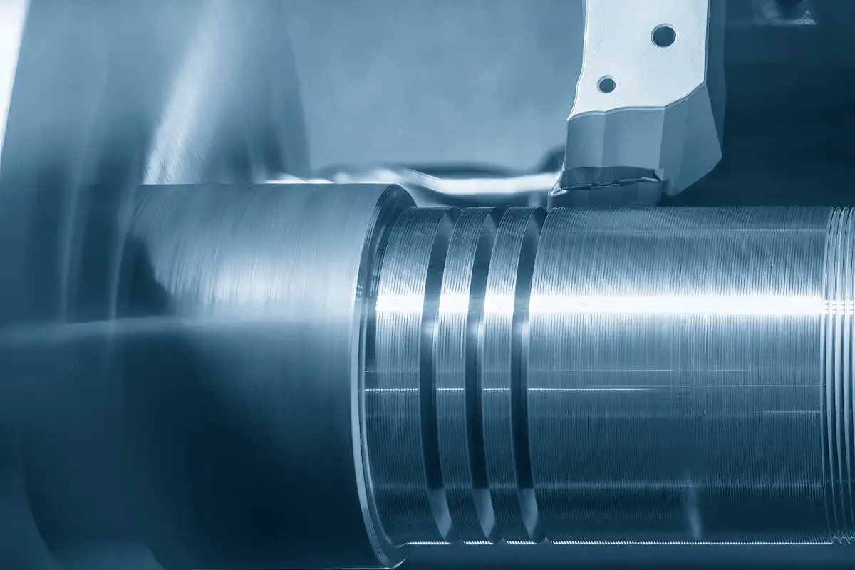
I. Common Threads
1. The impact of thread turning tool geometry angles on thread turning
The thread turning tool is shown in Figure 1, and it is usually clamped on an elastic tool holder for use, as shown in Figures 1b and 1c. This is to protect the tool tip by acting as a buffer when uneven forces are encountered during cutting. When turning threads, using the correct cutting fluid can reduce the surface roughness value of the machined surface.

a) Thread turning tool with rake angle γ₀ = 0°
b) Thread turning tool mounted on a regular elastic tool holder
c) Thread turning tool mounted inside a rotary tool holder
(1) The impact of tool rake angle on thread turning
The rake angle at the tip of the thread turning tool is called the radial rake angle γ₀. Theoretically, it conforms to the definition of rake angle, while the two side edges do not conform to the rake angle definition, but are still conventionally called rake angles. When turning common threads, the radial rake angle γ₁ of the tool is 0°, and the tool tip angle ε₂ equals the thread form angle α, i.e., ε₃ = α = 60°, so that the turned thread form is correct.
When the radial rake angle γ₀ of the thread turning tool (Figure 2) is greater or less than 0°, the two cutting edges in thread turning are not parallel to the workpiece’s axis, and the turned thread sides are not straight lines but slightly curved lines. Moreover, the larger the radial rake angle, the greater the error in the thread form half-angle, i.e., the actual thread form angle is larger than the standard thread form angle. The axial thread form cross-section turned out is shown in Figure 3.
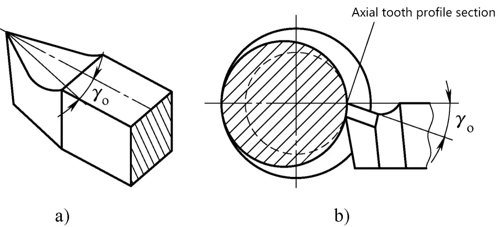
a) Thread turning tool with radial rake angle γ₀ > 0°
b) Cutting workpiece with γ₀ > 0° thread turning tool
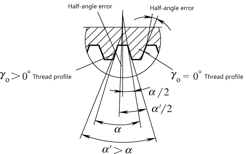
Therefore, when fine turning threaded workpieces with high precision requirements, to ensure the accuracy of the thread form, the rake angle of the tool is generally taken as 0° to 5°.
(2) The impact of tool tip angle on thread turning
As mentioned earlier, when the radial rake angle γ₀ of the thread turning tool is > 0°, it will affect the thread form angle, and the larger the radial rake angle, the greater the impact. When the radial rake angle γ₁ > 0°, if the tool tip angle ε₂ equals the thread form angle α, the turned thread form angle will be larger than required.
However, for threads with lower precision requirements, to increase the tool rake angle for easier cutting, in practical work, the method of appropriately reducing the tool tip angle can be used to obtain a relatively accurate thread form angle. When the radial rake angle γ₀ of the thread turning tool is < 12°, the tool tip angle ε₁ can be approximately calculated using the following formula:
εr=αcosγo
Where
α – Thread form angle (°);
γ₀ – Radial rake angle of the thread (°).
In situations where calculations are not convenient, when the radial rake angle γ₀ of the thread turning tool is < 12°, the tool tip angle can be made 1° ± 0.3° smaller than the thread form angle.
(3) The impact of the tool’s two side edge relief angles on thread turning
When turning threads, the turned groove is a helical line. Due to the inconsistency of thread lead angles for different workpieces, the contact angle between the back of the thread turning tool and the side of the thread form also varies. The larger the thread lead angle of the workpiece, the larger the tool relief angle during cutting.
If this angle change is not taken into account, it may cause the back of the tool to come into contact with the side of the thread form, or even scratch it. This factor’s influence should be especially considered when machining large pitch threads.
For this reason, when turning right-hand threads, the left relief angle α₀ at the left cutting edge of the thread turning tool should be increased slightly, adding a thread lead angle τ to the original relief angle α₁, i.e., α₂ = α₃ + τ. At this time, the right relief angle α₄ at the right cutting edge should be reduced, subtracting a thread lead angle τ from the original relief angle α₅, i.e., α₆ = α₇ – τ.
The tool relief angles for turning left-hand threads are opposite to the above, namely
αo left=αo-τ,αo right=αo+τo
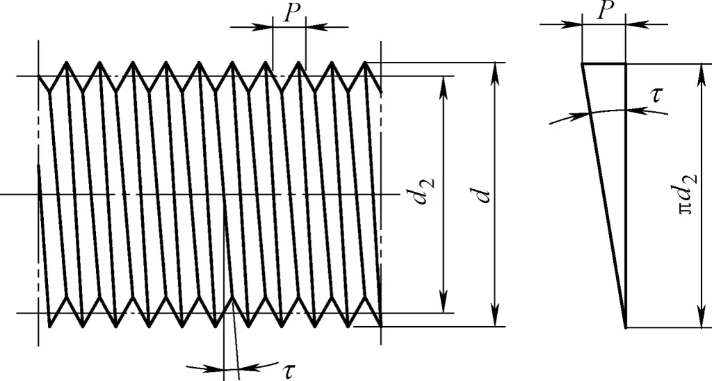
The thread lead angle τ is shown in Figure 4 and calculated using the following formula
tanτ=P/πd2
Where
P – Thread pitch (mm);
d₀ – Thread pitch diameter (mm).
When adjusting the two side edge relief angles of the thread turning tool during thread turning, a rotary spring tool holder can be used.
2. Take effective measures to ensure cutting stability
When turning threads on slender shaft-like workpieces, they are prone to bending under the action of the back force due to their poor rigidity. To prevent and reduce this occurrence, in addition to using a follow rest, a steady rest tool can also be used.
As shown in Figure 5, when turning threads on slender workpieces, a lightweight and stable steady rest is used. The clamp block is installed on the tailstock center, the support rod is fixed in the clamp block, and the bronze steady rod is clamped on the support rod. There is a V-shaped notch at the end of the steady rod that contacts the rotating workpiece to counteract the forces produced by the cutting tool during turning.
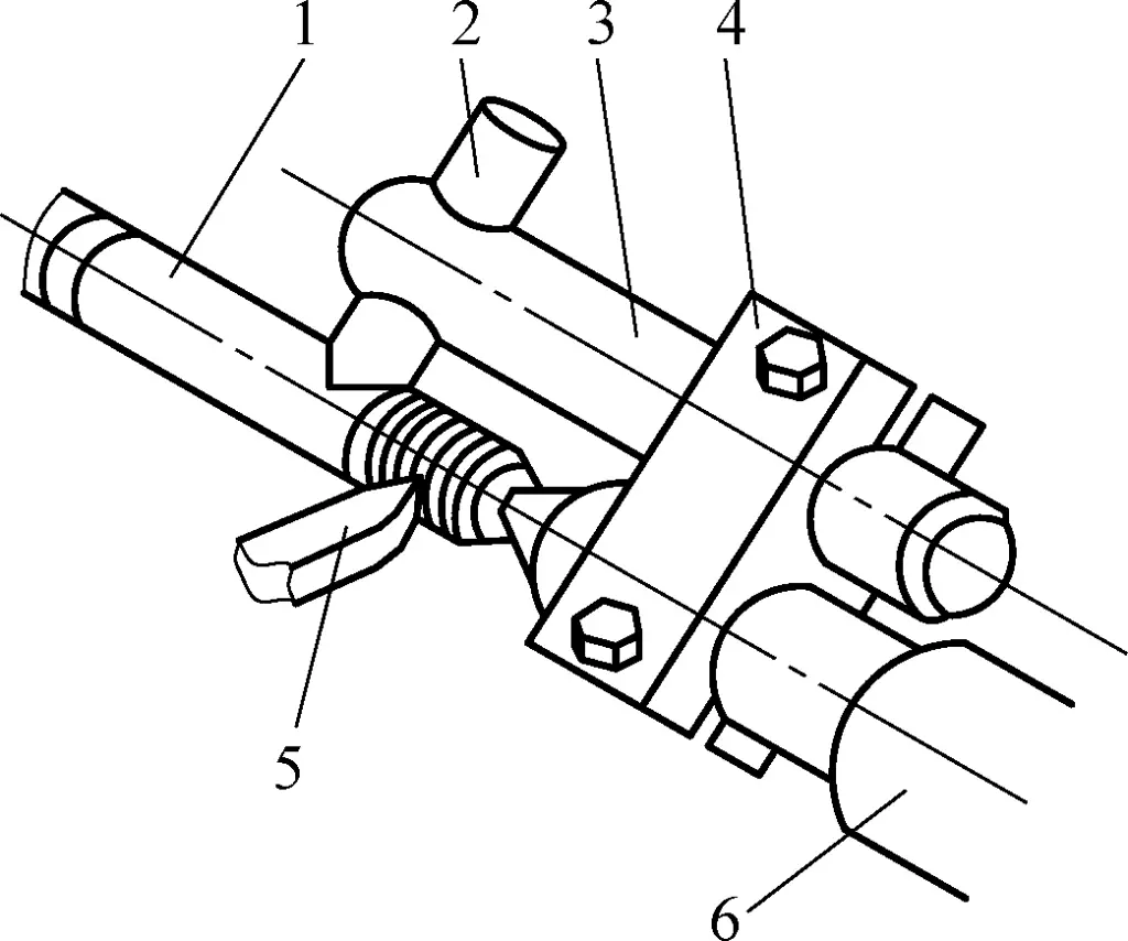
1—Workpiece
2—Copper steady rod
3—Support rod
4—Clamp block
5—Cutting tool
6—Tailstock
When installing this device, the steady rod should be at an angle to the horizontal plane, and the V-shaped notch of the steady rod should be slightly inclined towards the cutting tool direction to balance the combined force of the cutting tool on the rod.
Due to the limitation of the support rod length, this device is suitable for turning relatively thin threaded rods of short length.
Figure 6 shows the steady rest tool used when turning an M3 thin threaded rod in situations where it is inconvenient to use a tailstock center.
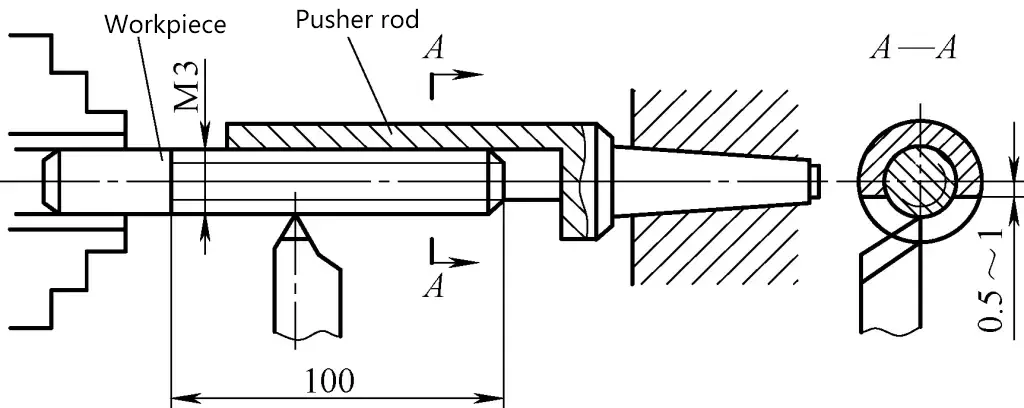
Place the steady rod into the tailstock and properly adjust the tailstock offset to ensure good contact with the workpiece surface. Using such a tool can ensure that the workpiece does not bend after machining.
When manufacturing this tool, ductile steel should be used, and the supporting surface of the steady rod should be ensured to be parallel to the lathe spindle centerline.
When turning long threaded rods with high precision requirements, the steady rest tool shown in Figure 7 can be used. While using a follow rest, a spring-loaded pin is installed on the right side of the cutting tool, effectively ensuring the stability of the workpiece and preventing vibration during cutting.
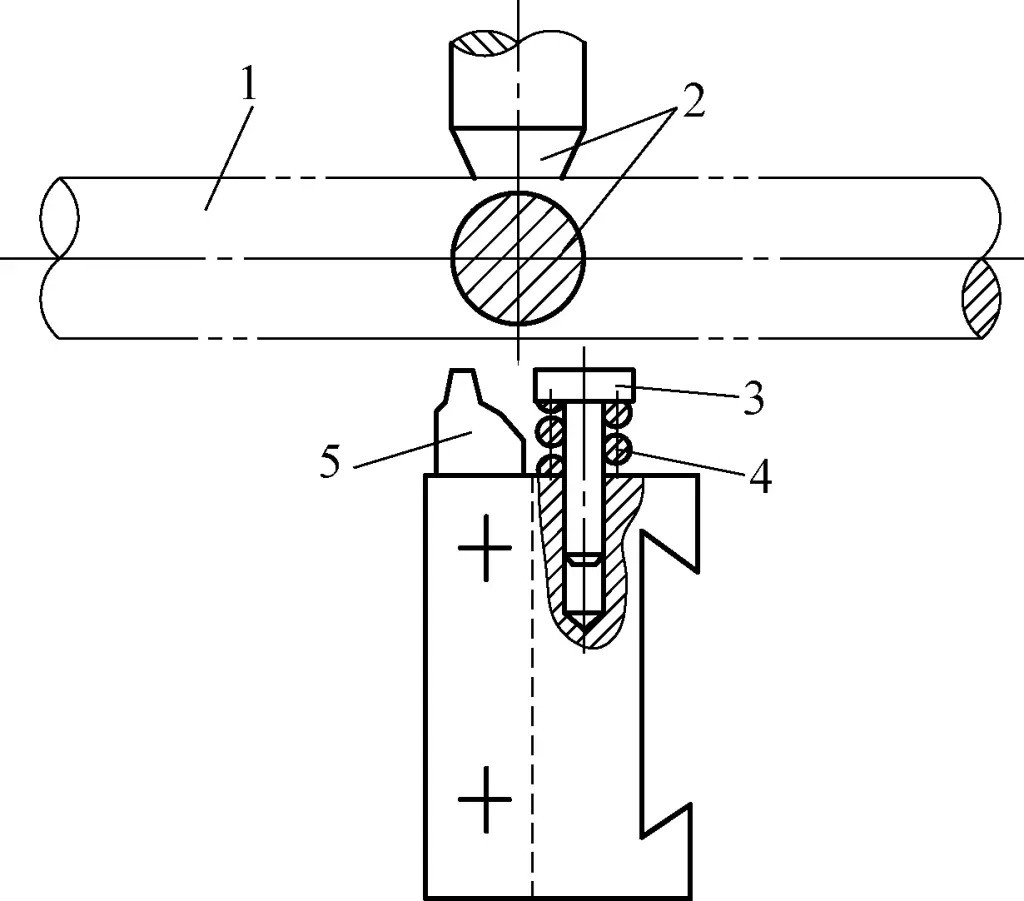
1—Workpiece
2—Follow rest jaw
3—Pin
4—Spring
5—Cutting tool
When using this device, pay attention to adjusting the relative position between the follow rest jaw and the pin, and ensure that the spring has a certain compression force to guarantee the supporting force of the pin.
3. Preventing the axial movement of the lathe’s long leadscrew from affecting the thread pitch of the workpiece
Excessive deviation in the thread pitch of the machined thread will affect its screwability. The main reasons for thread pitch errors are the precision issues of the lathe itself and operational mistakes, such as excessive axial movement of the lathe’s long leadscrew.
The method to inspect the axial movement of the leadscrew is as follows: Fix a dial indicator with a magnetic base on the lathe bed surface (Figure 8), stick a steel ball in the center hole of the leadscrew, rotate the leadscrew, and check by opening and closing the half nut in the apron at the middle section of the leadscrew.
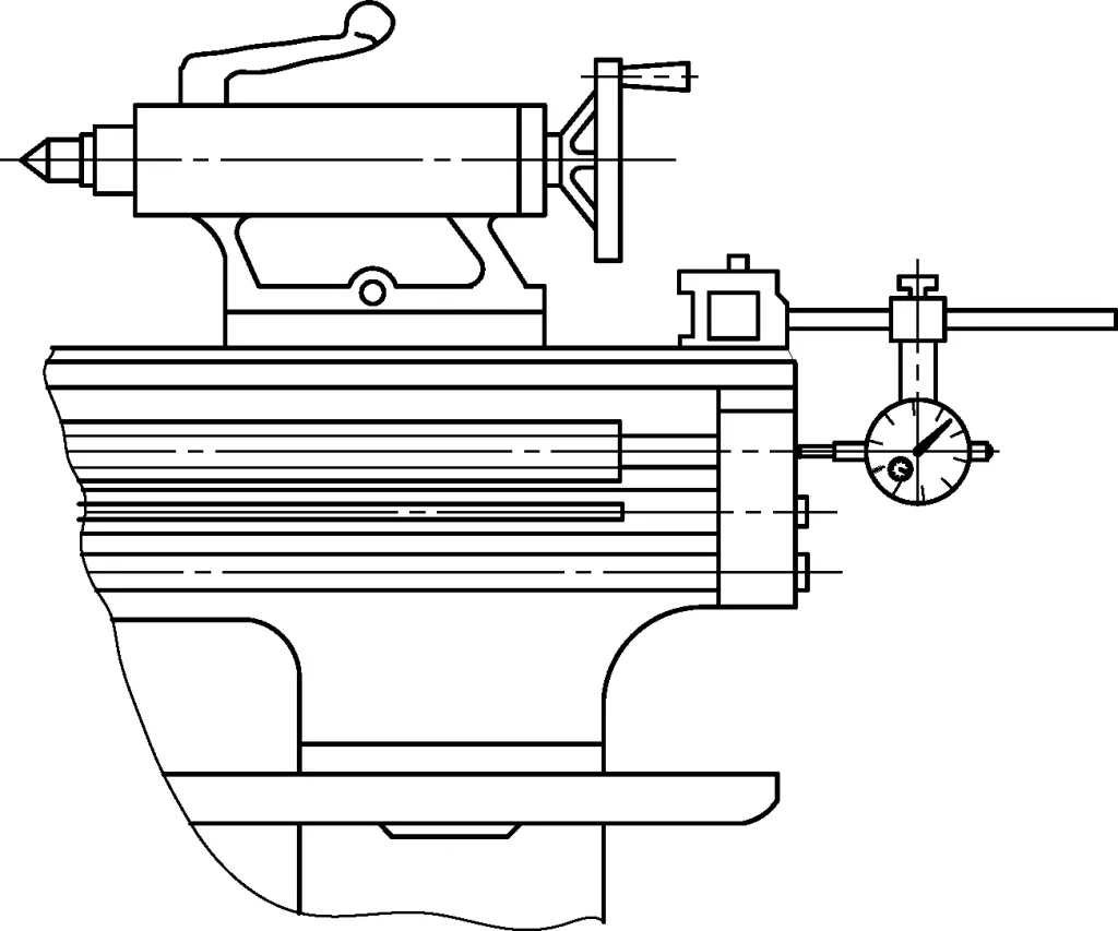
The maximum difference in the dial indicator readings is the axial movement error of the long leadscrew, with a tolerance of 0.015mm. If it exceeds this tolerance, careful adjustment should be made.
For threads with lower precision requirements, if the pitch exceeds the tolerance, to avoid affecting the screwability of the thread, the pitch diameter of the workpiece’s nut can be turned slightly larger. This will create some clearance at the pitch diameter during thread connection, allowing it to meet the screwability requirements.
This clearance is generally called compensating clearance. However, the pitch diameter compensation value cannot be increased indefinitely, as it would affect the reliability of the connection. Therefore, the size of the pitch diameter compensation value must be limited. Limiting the size of the pitch diameter compensation value also limits the magnitude of the pitch error.
Additionally, the axial movement of the lathe spindle, improper clearance between exchange gears, excessive parallelism of the lathe bed to the workpiece axis, or excessive straightness of the bed can all affect the pitch accuracy of the threaded workpiece.
4. Improving the efficiency of thread turning
Improving workpiece efficiency involves many aspects, such as improving processing methods, using multiple cutting tools for multi-start thread workpieces, increasing cutting parameters, using advanced cutting tools, using quick-change fixtures or adopting quick clamping methods, reducing idle time during operations, shortening measurement time, and rationally arranging the workspace. Below are a few examples of specific processing methods for illustration.
(1) Unloading method for tapered shank threaded workpieces
When turning tapered shank threaded workpieces, to facilitate workpiece installation and improve efficiency, the workpiece is usually inserted into the corresponding tapered hole for processing. However, if the unloading method is improper, it can waste time.
Figure 9 shows a clamping tool for tapered shank threaded workpieces, which can quickly unload the workpiece. The fixture body 1 has an external threaded portion with a knurled nut 2 screwed on it. The knurled nut has 4 holes for turning.
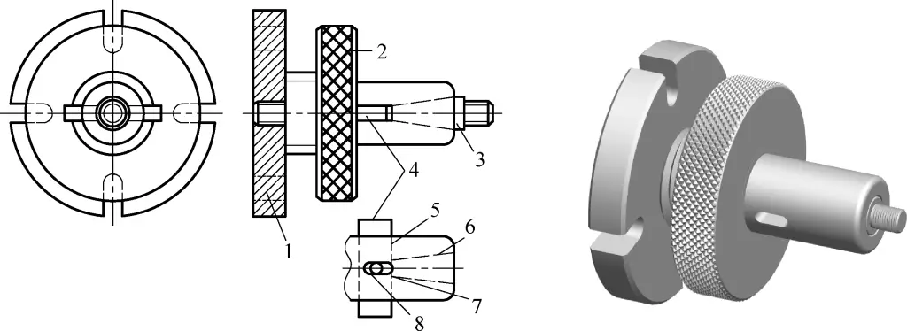
1—Fixture body
2—Knurled nut
3—Tapered shank threaded workpiece
4—Ejector plate
5, 7—Slots
6—Tapered hole
8—Small pin
There is a transverse slot 5 behind the tapered hole 6, with an ejector plate 4 installed in slot 5. The ejector plate has a small pin 8 that moves in slot 7 to keep the ejector plate in slot 5. After the tapered shank threaded workpiece 3 is finished, turning the knurled nut 2 outward will cause the ejector plate 4 to push out the tapered shank threaded workpiece 3.
(2) Adopting high-speed turning method
High-speed thread turning has advantages such as low surface roughness of the cut surface and high efficiency. However, due to increased cutting temperature, it can cause “expansion deformation” of the thread crests. Therefore, the outer diameter of external threads should be turned to the minimum limit size, and the hole diameter of internal threads should be turned to the maximum limit size.
(3) Reverse feed method in high-speed thread turning
During high-speed thread turning, the spindle speed is very high (its cutting speed is 6 times or even higher than when using high-speed steel cutting tools), and the feed rate is also very fast (generally only 3-5 feed passes are needed to complete the thread). Especially when turning large pitch threads and internal threads, accidents often occur due to inability to retract the tool in time. In such cases, the reverse feed method can be adopted.
Figure 10a shows the situation of high-speed turning of external threads using the reverse feed method. A cutting tool similar to that used for internal thread turning is mounted on the tool post, with the tool tip positioned at the tool retraction groove of the workpiece. After adjusting the back engagement amount, the lathe spindle rotates in reverse, and feeds from left to right at high speed to cut the thread.
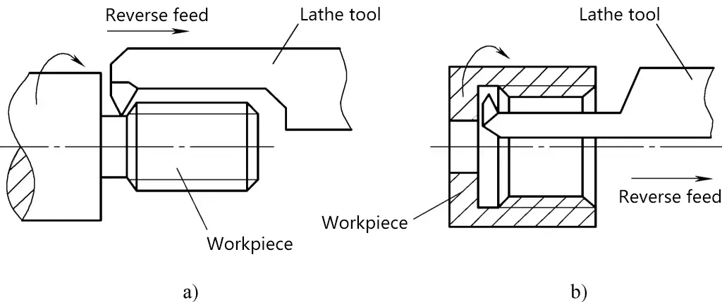
a) Reverse feed turning of external threads
b) Reverse feed turning of internal threads
This way, there is no issue of the cutting tool not being able to retract. Figure 10b shows the internal thread cutting tool ground in reverse. After adjusting the back engagement amount, the workpiece rotates in reverse, and the thread is cut by feeding from left to right.
(4) Using non-stop fixtures
Figure 11 shows a round nut workpiece. For single-piece production, it can be clamped in a self-centering chuck for processing. For mass production, to improve efficiency, a non-stop fixture as shown in Figure 12 can be used.
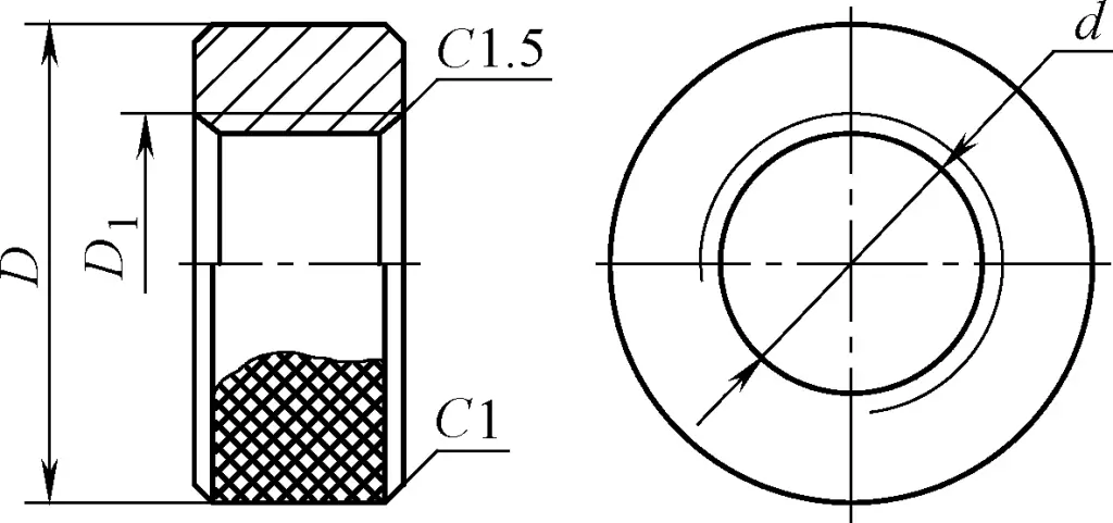
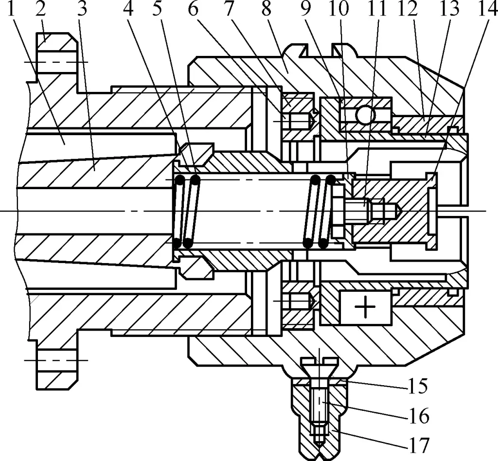
1—Spindle
2—Flange
3—Spring shaft
4—Spring collet
5—Spring
6, 11, 16—Screws
7-Locking disc
8—Outer sleeve
9—Bearing
10, 15—Washers
12—Copper bushing
13—Thrust sleeve
14—Collet core
17—Handle
The flange 2 is fixed to the lathe spindle box flange, and the spring collet 4 and spring shaft 3 are connected to the lathe spindle 1 in sequence and rotate with spindle 1. The outer sleeve 8 is connected to flange 2 via threads and does not rotate with spindle 1.
During processing, place the round nut workpiece into the hole of the rotating spring collet 4, turn the handle 17 counterclockwise to make the outer sleeve 8 rotate and move to the left along the axis, driving the thrust sleeve 13 to move left synchronously, thus clamping the workpiece.
After processing is complete, with the lathe spindle still rotating, turn the handle 17 clockwise to make the outer sleeve 8 rotate and move to the right, with the thrust sleeve 13 moving right synchronously. At this time, the spring collet 4 loosens, and under the action of spring 5, pushes the collet core 14, causing the workpiece to automatically fall off. Then, without stopping the machine, install the next workpiece to continue processing.
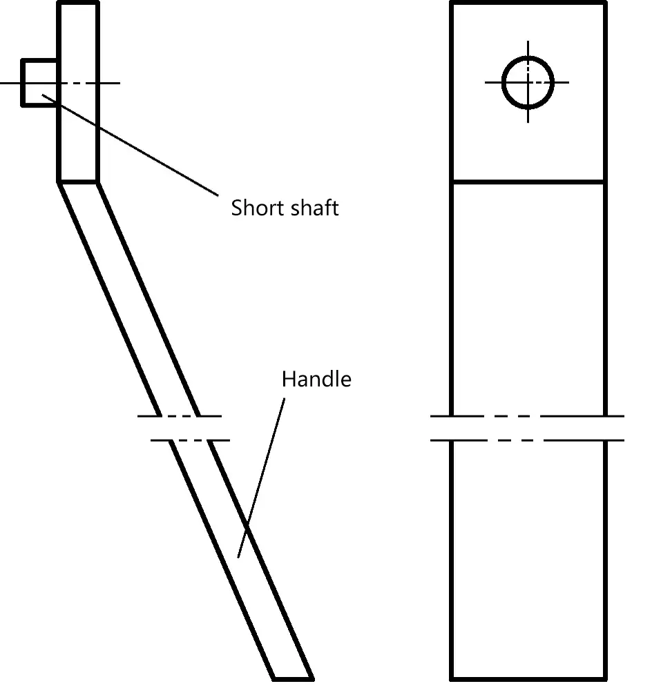
Since this fixture operates without stopping the machine, to prevent the workpiece from cutting the operator’s fingers during installation, an auxiliary tool as shown in Figure 13 can be used. Thread the round nut tool onto the short shaft and hold the handle to place the workpiece into the fixture.
(5) Double-tool turning of double-start threads
For processing double-start threads, it is generally done by first turning one lead, then dividing the line and turning the other lead. If a double-tool tool holder is used, productivity can be improved.
Figure 14 shows the structure of a tool holder for turning double-start internal threads. Two thread-cutting tools are mounted on the tool holder, both made of 10mm × 10mm high-speed steel, with the two tools forming one pitch. The length L of the tool shank is determined based on different workpiece lengths, and the shank must have sufficient rigidity to meet general-purpose requirements.
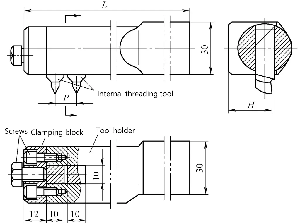
The left end of the tool shank is made elliptical for easy chip removal. For ease of manufacturing, the cutting tools are installed in open slots and secured by screws. When grinding the cutting tools, a template should be used for tool setting, and thin copper shims can be used between the two tools to ensure the pitch.
To ensure consistency of the front faces of both cutting tools, after assembly, the front faces are ground at once on a tool grinder. The tool geometry angles are selected according to conventional parameters.
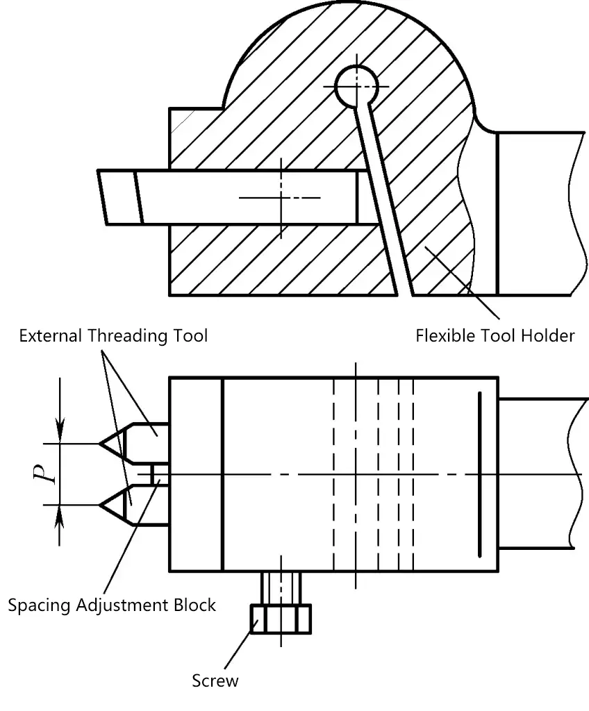
Figure 15 shows the structure of a double-tool holder for turning double-start external threads, which works on the same principle as the internal thread double-tool holder.
5. Using automatic tool retraction device for thread turning
In high-speed thread turning, due to the rapid longitudinal feed, if the cutting tool cannot be retracted in time when it reaches the end of the thread, it may damage the tool or workpiece.
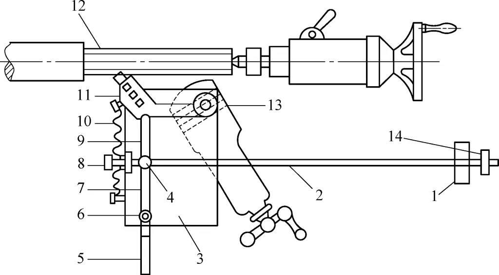
There are various forms of automatic tool retraction devices for thread turning. Figure 16 shows a relatively simple structure. It rotates the tool post by 29° and fixes a flat plate 3 on it. A pin 6 is fixed on the flat plate 3, with a connecting rod 7 having an adjusting handle 5 pivoted on pin 6. The inner end is pivoted on pin 4 on the long rod 2, and another connecting rod 9 is also pivoted on pin 4. The tool holder 11 is pivoted on the tool post bolt 13.
1—Stop block
2—Long rod
3—Flat plate
4, 6—Pins
5—Handle
7, 9—Connecting rods
8—Initial adjustment screw
10—Spring
11—Tool holder
12—Workpiece
13—Tool post bolt
14—Contact ring
When threading, as the tool reaches the end, the contact ring 14 fixed on the long rod 2 touches the stop block 1 fixed on the bed. The long rod 2 pulls the pin 4, causing the connecting rod 9 to gradually retract. The tool holder 11, pulled by the spring 10, also gradually moves away from the workpiece 12. When first using this device, adjust it using the initial adjustment screw 8.
II. Trapezoidal Thread
1. Trapezoidal Thread Cutting Tool
(1) Width dimension of the trapezoidal thread cutting tool’s top edge
The width dimension B of the trapezoidal thread cutting tool’s top edge (Figure 17) should be determined based on the size of the thread groove bottom. According to GB/T5796.1—2005 and GB/T 5796.3—2005, the width dimension of the tool’s top edge can be calculated using the following formula
B=0.366P-0.536a₀
Where
P – Pitch of trapezoidal thread (mm).
a c – Trapezoidal thread crest clearance (mm), when P=2~5mm, a c =0.25mm; when P=6~12mm, a c =0.5mm; when P=4~44mm, a c =1mm.
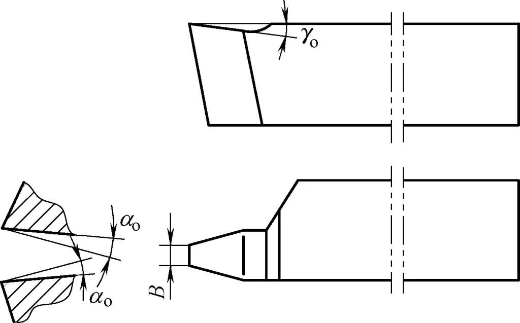
(2) Relationship between the working angle of the thread cutting tool and the thread lead angle
When cutting ordinary threads, due to the inconsistency of thread lead angles on different workpieces, the relief angles on both sides of the cutting tool affect thread cutting.
When cutting trapezoidal threads, this phenomenon becomes more evident due to the increased thread lead angle. The thread lead angle τ changes the actual relief angle during cutting. On the left cutting edge, the actual relief angle is reduced by τ due to the thread lead angle τ; while on the right cutting edge, it is increased by τ.
For this reason, when cutting right-hand threads and determining the relief angle of the trapezoidal thread cutting tool, the relief angle on the left cutting edge should be increased by τ. Since the relief angle of trapezoidal thread cutting tools is generally 3°~5°, it becomes (3°~5°)+τ, as shown in Figure 18.
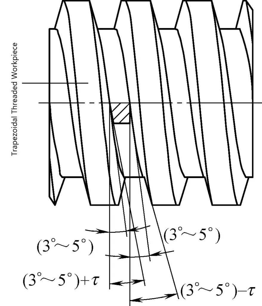
The relief angle on the right cutting edge must be reduced by τ, becoming (3°~5°)-τ, thus ensuring equal relief angles on both sides during actual cutting. For left-hand threads, the opposite applies.
In actual machining, to improve the impact of the thread lead angle on the tool’s working angle, the relative position of the tool and the workpiece can be appropriately adjusted.
Using a rotatable tool holder, rotate the tool by the workpiece’s thread lead angle and install the tool normally (Figure 19), or during grinding, grind the left side relief angle larger and the right side relief angle smaller. Also, increase the radial positive rake angle γ o appropriately in the depth cross-section (the radial positive rake angle γ o is shown in Figure 18, generally increased by 5°~15° depending on the material being machined).
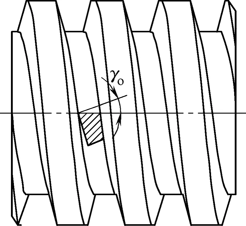
(3) Thread form angle of trapezoidal thread cutting tool and its correction
For thread cutting tools with a radial rake angle, as the two cutting edges do not pass through the centerline of the trapezoidal thread workpiece, the thread form in the axial cross-section of the cut thread is not a straight line but a curve. This error significantly affects the thread form angle, especially for thread cutting tools with large radial rake angles.
Therefore, the thread form angle of the cutting tool must be corrected during cutting. The correction value for the thread cutting tool’s form angle can be found in Table 1.
Table 1 Correction values for trapezoidal thread cutting tool form angle
| Trapezoidal thread form angle α | Tool radial rake angle γo | Tool thread form angle α1 |
| 30° | 5° | 29°54′ |
| 10° | 29°38′ | |
| 15° | 29°9′ |
2. Trapezoidal thread cutting tool holder structure
The tool holder structures introduced in Figures 1b and 1c are also suitable for cutting external trapezoidal threads. For internal trapezoidal threads, refer to the tool form shown in Figure 17. When cutting long and thin internal trapezoidal threads, the tool holder structure is as shown in Figure 20, which solves the problem of poor rigidity due to the thin and long tool holder.
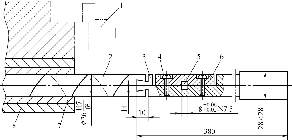
1—Chuck jaw
2—Through shaft
3—Tool body
4—Screw
5—Tool mounting hole
6—Pressure plate
7—Copper bushing
8—Transition sleeve
In Figure 20, the transition sleeve and copper bushing are installed in the lathe spindle’s tapered hole. The through shaft is inserted through the workpiece hole into the copper bushing, with its right end connected to the tool holder via a dovetail joint (the dovetail angle should be 75°~80°). A spiral oil groove is cut on the through shaft to ensure lubrication between it and the copper bushing, reducing friction resistance when the through shaft moves axially.
During machining, the workpiece is clamped by the jaws of a self-centering chuck. The cutting tool is installed in the square hole of the tool body, tightened with screws, and clamped with a pressure plate. Care should be taken to adjust the height of the tool tip to align with the lathe spindle center.
During cutting, neither the tool body nor the through shaft rotates. The dovetail joint connection allows the tool holder to feed both axially and radially. The through shaft, supported by the copper bushing, greatly enhances the rigidity of the tool holder, preventing vibration and chatter, thus ensuring cutting quality.
3. Example of cutting a trapezoidal thread workpiece
The workpiece to be machined is a 2000mm long trapezoidal thread lead screw, made of 45 quality carbon steel. The required straightness is not to exceed 0.03mm over 500mm. The cumulative pitch error over the entire length of the lead screw should not exceed 0.06mm, and the thread surface roughness Ra value should reach 3.2μm.
The machining process is as follows:
(1) First, perform general rough machining to remove the outer surface scale.
Normalize to remove internal stress (if conditions allow, the lead screw can be heated vertically in the furnace).
(2) Semi-finish and finish turn the major diameter of the lead screw.
(3) Rough cut the thread.
Leave 0.15~0.25mm allowance for semi-finishing the minor diameter of the thread, and 0.3~0.4mm allowance for semi-finishing both sides of the thread.
When cutting threads at high speed, to prevent metal extrusion deformation and damage to the follower rest jaws, a groove can first be cut at low speed using a high-speed steel cutting tool. The groove width can be 0.1mm narrower than the thread width, with a depth of about 0.5mm, and a tool retraction groove should be cut at the left end.
The cutting tool used for rough cutting trapezoidal threads is shown in Figure 21. The insert is made of YT15 carbide. The front and back faces of the tool should be polished with a grinding stone.
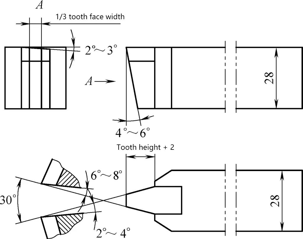
Cutting parameters: For pitches within 6mm, spindle speed n=600r/min. For smaller pitches, direct radial feed is used (Figure 22a), using thread cutting tools with different tip widths for rough and finish cutting, as shown in Figure 22b. For pitches above 6mm, spindle speed n=350r/min, with a back-cut depth ap =0.2~0.4mm.
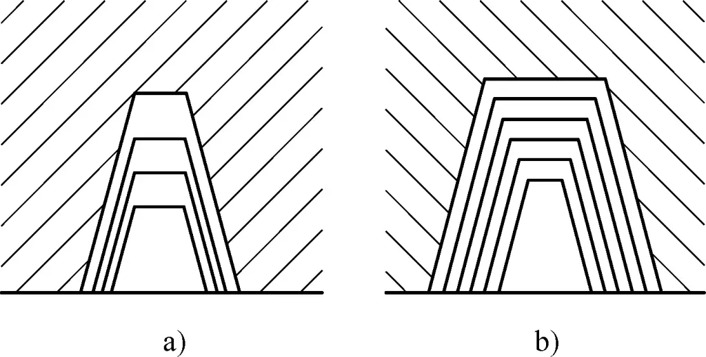
a) Direct radial feed
b) Cutting with tools of different widths
(4) Semi-finish cut the thread.
Leave 0.1mm allowance for finish cutting the minor diameter of the thread, and 0.15~0.2mm allowance for finish cutting both sides of the thread.
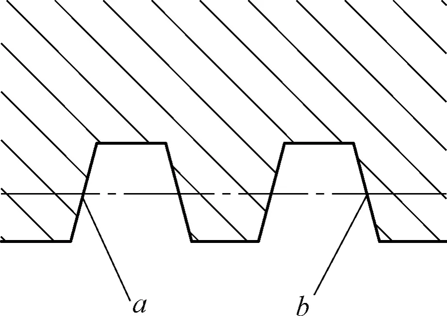
First semi-finish cut the thread bottom, then semi-finish cut the a face opposite to the feed direction, as shown in Figure 23. This is because the a face is more difficult to cut than the b face (for right-hand threads), and it generates cutting forces on the side where the lathe half nut has clearance, easily causing vibration and affecting thread surface roughness. The cutting tool shown in Figure 21 can still be used for semi-finish cutting.
(5) Check the straightness of the lead screw.
If the straightness of the lead screw exceeds the tolerance, adjustments should be made.
(6) Finish cut the thread.
First finish cut the minor diameter of the thread, then machine the a face. Next, check the thread angle using a tooth depth gauge smaller than the tooth depth. Finally, machine the b face and check with a finished product gauge or specialized measuring tool.
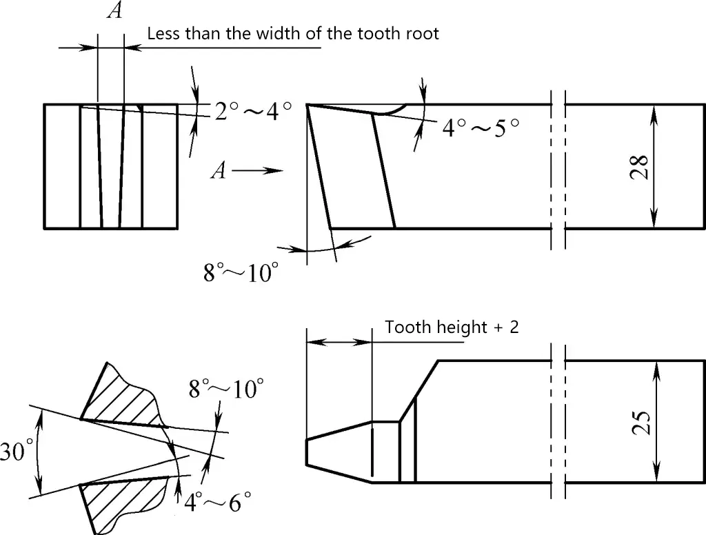
For finish cutting the thread, use a high-speed steel trapezoidal thread cutting tool as shown in Figure 24. Before cutting, polish the front and back faces with a grinding stone to achieve a surface roughness Ra value below 0.4μm. The selected cutting parameters are: spindle speed n=20~30r/min; feed rate for finishing both sides f=0.05mm/r.
Pay attention to the following points during operation:
1) Use a three-jaw follower rest, and add copper sleeves between the follower rest jaws and the workpiece to achieve good machining results, as shown in Figure 25. The width of the follower rest jaws should ideally be 30~35mm, preferably made of cast iron.
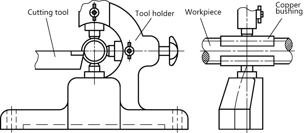
2) When cutting lead screws of different diameters, the mismatch between the arc radius of the follower rest jaws and the workpiece radius often results in single-point or double-point contact as shown in Figure 26, affecting machining quality.
In this case, after rough cutting, gently press the follower rest jaws against the workpiece surface and run for a distance at a speed above 600r/min. Use a grinding rod of the same diameter as the workpiece to grind the arc of the jaws, ensuring good contact surface and improving machining quality.
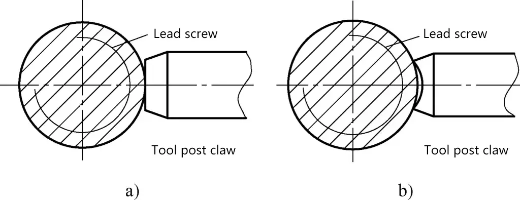
a) Single-point contact
b) Double-point contact
3) During cutting, use soapy water or emulsion for sufficient cooling and as a lubricant between the follower rest jaws and the workpiece.
4) For lead screws under 1000mm in length, use a front center and drive plate for clamping; for lead screws over 1000mm in length, generally use a chuck-and-center method for installation.
5) Use a high-precision rotating center at the tailstock. Regularly check and adjust the tightness of the center during operation. Do not apply excessive force to prevent bending and deformation of the lead screw.
Before turning trapezoidal threads on a relatively long and thin lead screw workpiece, stress relief treatment should be performed. This stress relief process is crucial as it affects whether the workpiece will deform or not.
Due to the length of the lead screw being machined, it often takes several working days to complete. Therefore, during the machining process, care should be taken not to stop the machine for long periods, otherwise, the workpiece will sag and bend under its own weight. During the machining process, neglecting any detail makes it difficult to meet the technical requirements.
4. Quality control in trapezoidal thread turning
(1) Solving the problem of surface ripples on threads
When turning trapezoidal threads with a larger pitch, the left side is often smoother, while the right side (Figure 27) has varying degrees of ripples. This not only affects the accuracy of the thread but also reduces its service life.
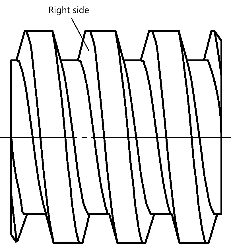
The formation of ripples on the thread surface is due to poor rigidity of the workpiece or lathe, chatter or crawling during cutting, and poor grinding precision of the cutting tool. Additionally, an important factor is the feed force on the cutting tool during the axial contact between the lathe lead screw and the nut transmission. When machining right-hand threads, the long lead screw rotates to drive the nut, moving the saddle towards the spindle.
At this time, the right axial clearance between the long lead screw and the nut is eliminated, so the feed force cannot be finely adjusted when turning the right side of the thread. As a result, a comprehensive feed force is generated between the cutting tool, spindle, and the right side of the thread, causing forced vibration.
To eliminate the influence of these factors, a single-sided cutting method can be adopted when finishing trapezoidal external threads with larger pitches. Use the lathe’s forward rotation and forward feed to cut the left side of the thread, as shown in Figure 28a; use the lathe’s reverse rotation and reverse feed (with the thread cutting tool installed in reverse) to cut the right side of the thread, as shown in Figure 28b. This can eliminate ripples on the right side of the thread.
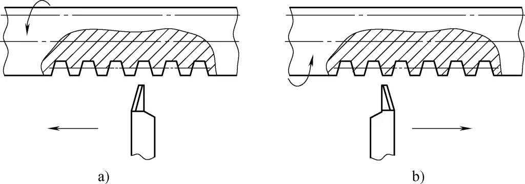
a) Cutting the left side of the thread
b) Cutting the right side of the thread
When machining internal threads, if the above two tool-setting methods are still used, the operation becomes very difficult. In this case, the internal thread cutting tool shown in Figure 29 can be adopted.
When cutting the right side of the internal thread, the feed force generated by cutting causes the tool shank to compress the spring and move axially on the main body. This not only reduces the surface roughness value of the thread but also makes it easier to ensure the angle and dimensional accuracy of the thread.
When using the cutting tool shown in Figure 29, the cutting speed can be selected as v₀ = 1.5-6m/min; for finishing, the back feed amount a₁ = 0.2mm, and for rough machining, a₂ > 0.2mm. Before cutting, strictly perform tool setting and alignment work. If conditions allow, a tool-setting microscope can be used to grind and install the cutting tool.
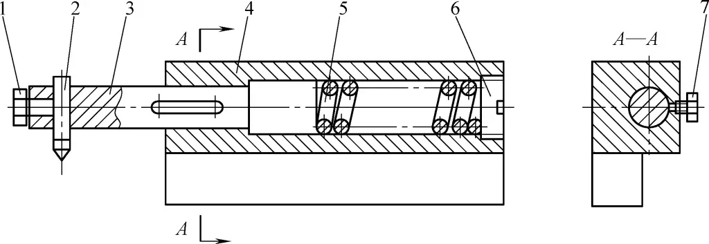
1—Fixing screw
2—Tool head
3—Tool shank
4—Main body
5—Spring
6—Screw plug
7—Positioning screw
(2) Solving the problem of single pitch tolerance exceeding in trapezoidal thread workpieces
For more precise long lead screw workpieces, the single pitch tolerance requirements are also quite strict. For example, a lead screw with a trapezoidal thread length of 5100mm and an outer diameter of 80mm; pitch error: single pitch tolerance is ±0.012mm, cumulative error within 300mm should not exceed 0.035mm, and cumulative error over the entire length of the lead screw should not exceed 0.08mm.
Due to the length of the workpiece, the midpoint of the lead screw sags by 20-30mm after clamping. To eliminate deformation and reduce vibration during cutting, a fixed center rest and a follower rest are installed on the bed. The fixed center rest interferes with the saddle’s passage during machining, so the method of machining half of the lead screw first, then turning it around to machine the other half is adopted.
The lead screws machined using this method have poorer accuracy, with single pitch errors between 0.015-0.025mm, and some can reach 0.03mm (non-conforming threads are distributed irregularly along the entire length of the lead screw). Especially at the joining point where the workpiece is turned around, the single pitch error can reach 0.08mm, exceeding the specified value by 5 times.
To solve the problem of single pitch tolerance exceeding, the following measures can be taken:
1) The single pitch tolerance exceeding at the joining point is mainly caused by turning the workpiece around and joining the cut. The most fundamental solution is to avoid joining the cut. In this case, the fixed center rest can be replaced with a movable center support, the structure of which is shown in Figure 30.
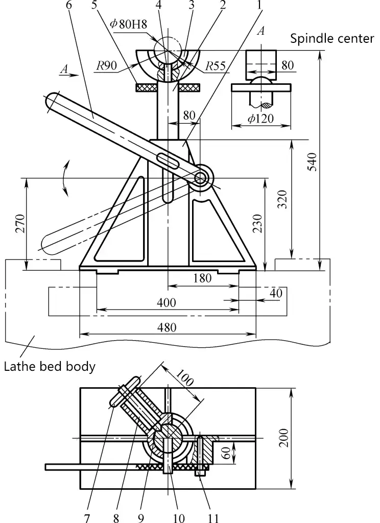
1—Support body
2—Support rod
3—Replaceable bushing
4, 11—Screws
5—Rubber ring
6—Handle
7—Pin shaft
8—Spring
9—Spring positioning pin
10—Small shaft
The bottom surface of the support body 1 matches the lathe guide rail, and the support rod 2 is placed in the support body. The support rod is lifted by the handle 6 and positioned by the spring positioning pin 9. When not in use, manually pull out the spring positioning pin, and the support rod will automatically drop due to its own weight. There are two such supports, placed on the left and right guide rail surfaces of the saddle.
At the beginning of machining, the left support supports the front-middle part of the lead screw, while the right support is pushed towards the tailstock and temporarily not used. During machining, when the cutting tool approaches the left support, first move the right support to the middle and raise it, while removing the left support.
To meet the rigidity requirements during cutting, the original follower rest can be replaced with a double-eared follower rest as shown in Figure 31. This type of follower rest has good centering, can withstand large forces, is stable and reliable, and can complete the cutting of the lead screw along its entire length with just one clamping. By adopting these measures, the pitch errors caused by joining cuts can be eliminated.
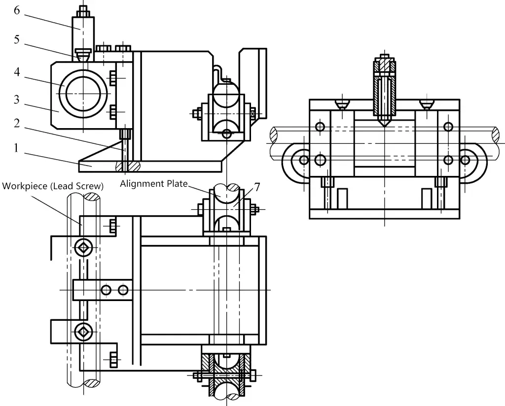
1—Tool rest body
2—Support screw
3—Lead screw support frame
4—Replaceable positioning sleeve
5—Oil cup
6—Top jaw
7—Alignment plate support wheel
2) To solve the problem of single pitch tolerance exceeding, controlling the half-angle of the thread tooth profile is very important. Correct installation of the cutting tool and proper tool setting are crucial steps that cannot be ignored in the process of solving single pitch tolerance exceeding.
Figure 32 shows the tool setting situation using a V-block type tool setting plate. It uses the V-shaped surface as a reference surface, spanning it across the workpiece, and accurately placing the tip of the thread cutting tool into the groove of the angle template to align the position of the thread cutting tool. When making this tool setting plate, ensure that the centerline of the tool setting groove (equal half-angles) is perpendicular to the V-shaped surface on the V-block.
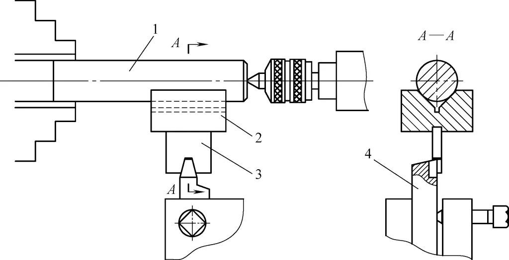
1—Threaded workpiece
2—V-block
3—Tool setting plate
4—Thread cutting tool
For very precise threads, the following method can be used for tool setting: Instead of using a tool setting plate, one side face of the thread cutting tool is used as a unified reference for tool grinding and setting.
Grind one side face of the thread cutting tool on a surface grinder, then grind the angle of the cutting tool. At this time, position using the ground side face and use a standard angle gauge block or sine bar to align the cutting tool angle. This way, the half-angle error of the ground cutting tool tip can be controlled within ±5′. During grinding, the up-and-down moving slide of the grinding wheel can be set to an angle equal to the back angle of the cutting tool to simultaneously grind the back angle of the cutting tool.
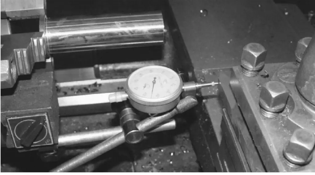
After grinding the thread cutting tool angle, place a dial indicator on the saddle with the indicator probe contacting the side face (reference surface) of the cutting tool (Figure 33). Rotate the cross slide and observe the dial indicator reading, adjusting the side face of the cutting tool until there is no needle movement. This way, the cutting tool position is accurately set. Using this method for tool setting, the half-angle error of the machined thread can be controlled within ±10′.
3) To ensure that the workpiece pitch error is within the allowable range, it is necessary to strictly ensure the straightness of the several cutting edges on the trapezoidal thread cutting tool and carefully polish them with a whetstone.
4) Ensure the cleanliness of the lathe lead screw. It must be thoroughly cleaned before machining and must not be contaminated with oil or chips. Generally speaking, the accuracy of the single thread pitch mainly depends on the machining method, as well as the accuracy of the lathe lead screw, errors in the transmission gears, and the rigidity of the workpiece system itself.
If individual pitch errors are found to exceed tolerance, the finest diamond powder can be used with a cast iron nut for lapping. This is a remedial measure but should not be overly relied upon.
(3) Control of burrs on trapezoidal thread crests
During high-speed turning of trapezoidal threads using carbide cutting tools, due to the limitations of the workpiece cross-section, relatively large burrs are produced at the corner of the thread crest under tool compression.
For short lead screws with good rigidity, a follower rest is generally not used, and an additional feed can be added before finish turning to remove the burrs. For long lead screws with poor rigidity, the presence of crest burrs will adversely affect the cutting process and workpiece accuracy.
For example: Crest burrs will damage the working surface of the follower rest support jaws, causing deep grooves; the interaction between crest burrs and the working surface of the follower rest support jaws produces debris and fine chips that get squeezed between the contacting surfaces, both accelerating the wear of the support jaws and damaging the outer cylindrical surface of the lead screw.
The friction and unstable force conditions between the crest burrs and the working surface of the follower rest support jaws easily induce vibration. In particular, the formation of crest burrs causes the actual diameter of the workpiece to exceed the initial workpiece diameter set when adjusting the follower rest, thus causing lateral bending of the workpiece under the action of the follower rest.
When grooves are worn into the working surface of the support jaws, a gap appears between the workpiece and the working surface of the support jaws, disrupting their good contact and causing vibration or workpiece bending deformation during the cutting process, and even leading to the inability to continue cutting.
The key to eliminating these drawbacks is to control the formation of crest burrs. Reasonable allocation of machining allowance and appropriate selection of cutting patterns are simple methods to limit the formation of crest burrs.
When high-speed turning lead screws, both the left and right side edges of the cutting tool, along with the top edge, participate in cutting simultaneously. The cutting pattern is shown in Figure 34.
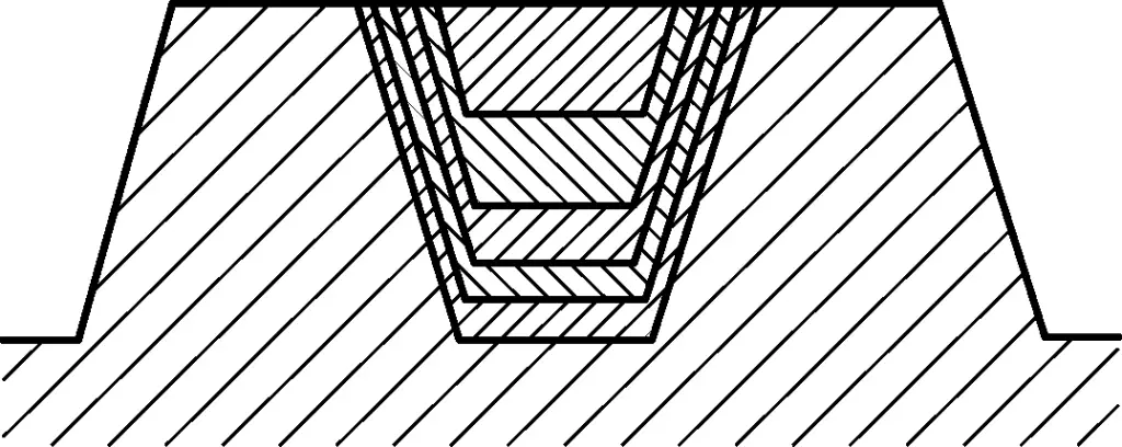
At this time, because the cutting edges on both sides of the tool need to cut the metal on the outer surface of the workpiece each time, as the number of feeds increases, the height of the burrs at the tooth top will become larger and larger. If the cutting pattern shown in Figure 35 is adopted, the top burrs can be greatly reduced or even eliminated. The specific cutting method is as follows:
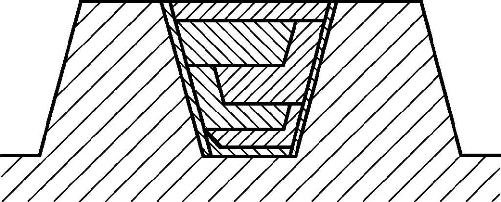
The specific cutting method is as follows:
First feed: Use a wide-edge turning tool that has been sharpened very keenly to cut a wide groove with a depth of 0.3 to 0.5mm. Due to the sharpness of the cutting edge and the small back cutting amount, the top burrs are very small or even non-existent. When determining the width of the turning tool, ensure that there is a 0.1 to 0.2mm finishing allowance on each side of the thread tooth.
Second feed: Switch to a trapezoidal thread turning tool. When feeding, ensure that the surface cut by one side of the turning tool coincides with the surface cut by the same side of the wide tool.
Third feed: The back cutting amount is the same as the second feed, and the surface cut by the other side of the tool should also coincide with the side surface cut by the wide tool.
Feed sequentially using the same method. The final finishing feed should remove the remaining finishing allowance.
Using this cutting method, except for the first feed and the final finishing feed, during the several feeds with heavier loads, the side edges of the turning tool do not directly cut the outer circle of the workpiece. Even if burrs are produced, they will not exceed the groove depth cut in the first feed. With a smaller finishing allowance, the top burrs produced after the workpiece is completed are very inconspicuous.
Practice has proven that using the above method for high-speed turning of lead screws can eliminate the impact of top burrs and the working surface of the tool rest support claws, reduce cutting deformation and residual stress, make the cutting process stable, resulting in higher workpiece accuracy and lower surface roughness values.

