Common threading methods mainly include tapping (commonly known as threading) and threading dies (commonly known as dies). Cutting internal threads in the workpiece hole with a tap is called tapping. Cutting external threads on a cylindrical rod with a die is called threading.
I. Thread Cutting Tools
A tap is a tool used to cut internal threads and comes in three types: hand taps, machine taps, and pipe thread taps. Usually, a set of hand taps for M6 to M24 sizes consists of two pieces, while sets for sizes below M6 or above M24 consist of three pieces. Regardless of size, fine thread taps always come in sets of two.
Machine taps come in sets of two. Each set of taps has equal major, medium, and minor diameters (hence also called equal diameter taps), differing only in the length and taper angle of the cutting part.
The cutting part ranges from long to short, and the taper angle (2φ) ranges from small to large, referred to sequentially as the head taper (initial taper), second taper (middle taper), and third taper (final taper). During tapping, the head taper cuts 60% of the metal, the second taper 30%, and the third taper 10%, serving to finalize the diameter and polish the thread.
Pipe thread taps come in cylindrical and conical forms. The 55° non-sealed pipe thread (commonly known as cylindrical pipe thread) tap is similar to a hand tap but has a shorter working section, generally consisting of two pieces per set, capable of cutting various 55° non-sealed pipe threads.
The diameter of a 55° sealed pipe thread tap gradually increases from front to back, while the thread profile remains perpendicular to the tap’s central axis, ensuring good contact between the internal and external thread profiles. Due to the high cutting load during operation, machine taps are more commonly used, though hand taps are also available.
II. Tapping
Tapping includes manual tapping and machine tapping.
1. Tapping Tools
The main tools for tapping include: wrench handles (commonly known as tap wrenches), safety chucks, and quick-change safety chucks for taps.
(1) Wrench Handle.
The wrench handle, also known as a tap wrench, is essential when manually tapping with a hand tap. The structure of the wrench handle is shown in Figure 1.
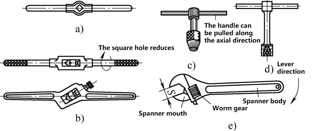
a) Fixed Wrench Handle
b) Adjustable Wrench Handle
c) T-Handle Tap Wrench
d) T-Wrench
e) Adjustable Wrench
Generally, fixed wrench handles are suitable for tapping holes of M5 and smaller. Adjustable wrench handles come in six sizes, ranging from 150-600mm, and can tap holes of M5 to M24. When tapping holes near high steps on workpieces or inside boxes, a T-wrench is needed.
(2) Tapping Safety Chuck.
When tapping on a machine, a safety chuck is used to clamp the tap, providing safety protection, preventing breakage, and facilitating replacement. It also allows for automatic withdrawal of the tap without changing the machine’s direction. The common safety chucks are as follows:
1) Elastic Friction Tapping Safety Chuck.
This safety chuck adjusts the torque by rotating an adjusting nut. During tapping, if the cutting torque suddenly exceeds the set torque, the outer sleeve stops rotating with the chuck body, providing safety protection. Different sized taps can be accommodated by changing the corresponding chuck and rubber ring.
2) Quick-Change Tapping Safety Chuck.
This chuck generates friction between the chuck body, center shaft, and friction plates by tightening the adjusting nut, driving the tap for threading. The adjusting nut’s tightness is set based on the tap size to ensure that it slips when exceeding a certain torque, providing safety protection.
2. Determining the Diameter of the Pre-Tapped Hole
During tapping, the tap not only cuts the metal but also exerts considerable pressure. To prevent the tap from jamming and breaking, the diameter of the pre-tapped hole should be larger than the minor diameter specified in the thread standards.
(1) Determining the Diameter of the Pre-Tapped Hole for Ordinary Threads.
The diameter of the pre-tapped hole for ordinary threads depends on the type of material processed, determined by the following formulas:
1) For steel or highly plastic materials, the drill diameter d0 is d0=D-P, where D is the major diameter of the thread (mm), and P is the pitch (mm).
2) For cast iron and less plastic materials, the drill diameter d0 is d0=D-(1.05~1.1)P.
The drill diameter for pre-tapped holes for ordinary threads can refer to Table 1.
Table 1 Drill Diameters for Pre-Tapped Holes for Ordinary Threads (Unit: mm)
| Thread diameter D | Pitch P | Drill diameter d0 | |
| Cast iron, bronze, brass | Steel, malleable cast iron, pure copper, laminated boards | ||
| 2 | 0.4 0.25 | 1.6 1.75 | 1.6 1.75 |
| 2.5 | 0.45 0.35 | 2.05 2.15 | 2.05 2.15 |
| 3 | 0.5 0.35 | 2.5 2.65 | 2.5 2.65 |
| 4 | 0.7 0.5 | 3.3 3.5 | 3.3 3.5 |
| 5 | 0.8 0.5 | 4.1 4.5 | 4.2 4.5 |
| 6 | 1 0.75 | 4.9 5.2 | 5 5.2 |
| 8 | 1.25 1 0.75 | 6.6 6.9 7.1 | 6.7 7 7.2 |
| 10 | 1.5 1.25 1 0.75 | 8.4 8.6 8.9 9.1 | 8.5 8.7 9 9.2 |
| 12 | 1.75 1.5 1.25 1 | 10.1 10.4 10.6 10.9 | 10.2 10.5 10.7 11 |
| 14 | 2 1.5 1 | 11.8 12.4 12.9 | 12 12.5 13 |
| 16 | 2 1.5 1 | 13.8 14.4 14.9 | 14 14.5 15 |
| 18 | 2.5 2 1.5 1 | 15.3 15.8 16.4 16.9 | 15.5 16 16.5 17 |
| 20 | 2.5 2 1.5 1 | 17.3 17.8 18.4 18.9 | 17.5 18 18.5 19 |
| 22 | 2.5 2 1.5 1 | 19.3 19.8 20.4 20.9 | 19.5 20 20.5 21 |
| 24 | 3 2 1.5 1 | 20.7 21.8 22.4 22.9 | 21 22 22.5 23 |
(2) Determination of the bottom hole diameter when tapping inch threads (commonly known as British threads).
When tapping inch threads, the drill diameter of the bottom hole is generally calculated using the following empirical formulas:
1) When machining steel or elastic-plastic materials, d0 = (D-0.9P) × 25.4mm.
2) When machining cast iron or materials with lower ductility, d0 = (D-0.98P) × 25.4mm, where P is the pitch of the inch thread, which is the reciprocal of the number of teeth per inch. For example, for 12 teeth per inch, P=1/12.
3. Determining the depth of the bottom hole for threading
When tapping blind holes, due to the taper angle of the tap’s cutting part, the depth H indicated in the drawing usually only includes the part with complete threads. Therefore, the depth H1 of the bottom hole should be greater than the thread hole depth H. Generally, H1 can be determined as H1=H+0.7D, where D is the major diameter of the thread.
4. Key points for manual thread tapping operations
The main points and methods for manual thread tapping operations are as follows:
1) The mouth of the bottom hole should be chamfered, and both ends of the through hole should be chamfered to prevent the thread from breaking when the tap enters and exits.
2) The workpiece should be clamped firmly and level. During thread tapping, the tap should be positioned correctly at the hole’s mouth, and then one hand should press the tap while the other hand turns the wrench. Continuously observe and adjust the tap’s position to ensure its correctness. After tapping 3-4 threads, there is no need to apply further pressure, just evenly turn the wrench with both hands.
3) When the tap enters the hole, it should be reversed by 0.5 turns for every 0.5-1 turn to break the chips, making it easier to remove them from the hole. This is especially crucial when tapping threads under M5, deep holes, or highly elastic-plastic materials.
When tapping blind holes, frequently withdraw the tap to remove chips from the hole. Upon reaching the bottom hole, ensure chips are removed to avoid the tap getting stuck.
4) First use the lead tap, then use the secondary tap. During the tap change, manually thread the tap into the hole until it can no longer be turned, then use the wrench to turn it. Apply lubricant when tapping elastic-plastic material holes.
5) When retracting the tap, first loosen it by reversing with the wrench, then remove the wrench and manually rotate it out to avoid damaging the thread hole’s surface finish.
5. Common methods for thread tapping
The commonly used methods for thread tapping are as follows:
(1) Completing both drilling the bottom hole and tapping the thread in one clamping setup.
When hand tapping a single piece, after drilling the bottom hole in the drilling machine, use a drill chuck to clamp a 60° cone, support the center hole of the tap shank, use a wrench to tap a few threads to ensure verticality, then remove the part and hand tap the thread.
For machine tapping, after drilling the bottom hole, replace with a machine tap to directly tap the thread.
(2) Common tools and fixtures for thread tapping.
When tapping a large number of thread parts, to ensure tapping quality and improve efficiency, commonly used tapping tools are shown in Figure 2.
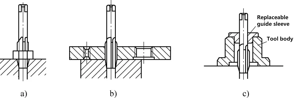
a) Using precision nuts to align taps
b) Plate-type multi-hole alignment tools for taps
c) Multi-purpose alignment tools with replaceable guide bushings
6. Sharpening of taps
When the tap wears out during thread tapping, the following methods can be used for sharpening.
(1) Sharpening the front cutting face of the tap.
When the wear on the front cutting face is not severe, first use a cylindrical oilstone to grind the tooth grooves’ front face, then lightly hone the front cutting face with a triangular oilstone as shown in Figure 3. During grinding, ensure the tooth tips are not rounded.

If the tap is severely worn, it needs to be sharpened on a tool grinder. Control the front angle during sharpening, as shown in Figure 4.
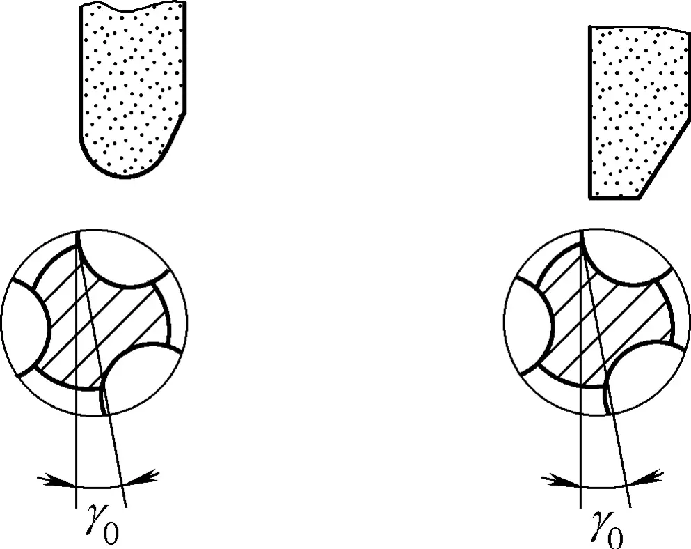
The size of the front angle γ0 of the tap is mainly determined based on the properties of the material being processed. Generally, reference Table 2 for selection.
Table 2 Selection of front angle size for taps [Unit: (°)]
| Processing material | Front angle (γ0) |
| Cast bronze | 0 |
| Cast iron | 5 |
| Alloy steel | 5 |
| Brass | 10 |
| Medium carbon steel | 10 |
| Low carbon steel | 15 |
| Stainless steel | 15~20 |
| Aluminum and aluminum alloys | 20~30 |
(2) Sharpening the rear cutting face of the tap.
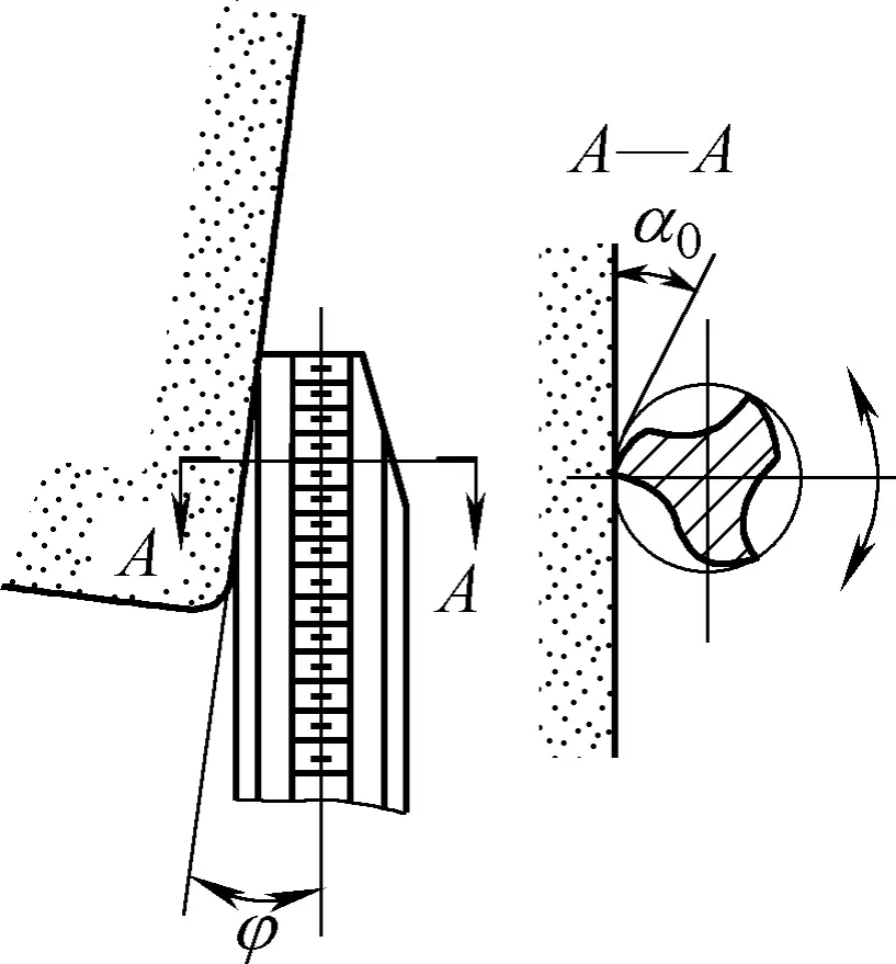
When the cutting part of the tap wears out, the rear cutting face can be ground on a tool grinding machine to ensure the consistency of the cutting cone angle and relief angle of each tooth groove of the tap. In actual production, operators can also grind the rear cutting face on a grinding machine, as shown in Figure 5. The method of grinding is similar to that of drill grinding, and the requirements are basically the same.
III. Die
The die is a tool for processing external threads. According to the different types of threads being processed, there are two types: circular dies and 55° sealing pipe thread dies. They are made of alloy tool steel or high-speed steel and undergo quenching treatment.
1. Circular Die
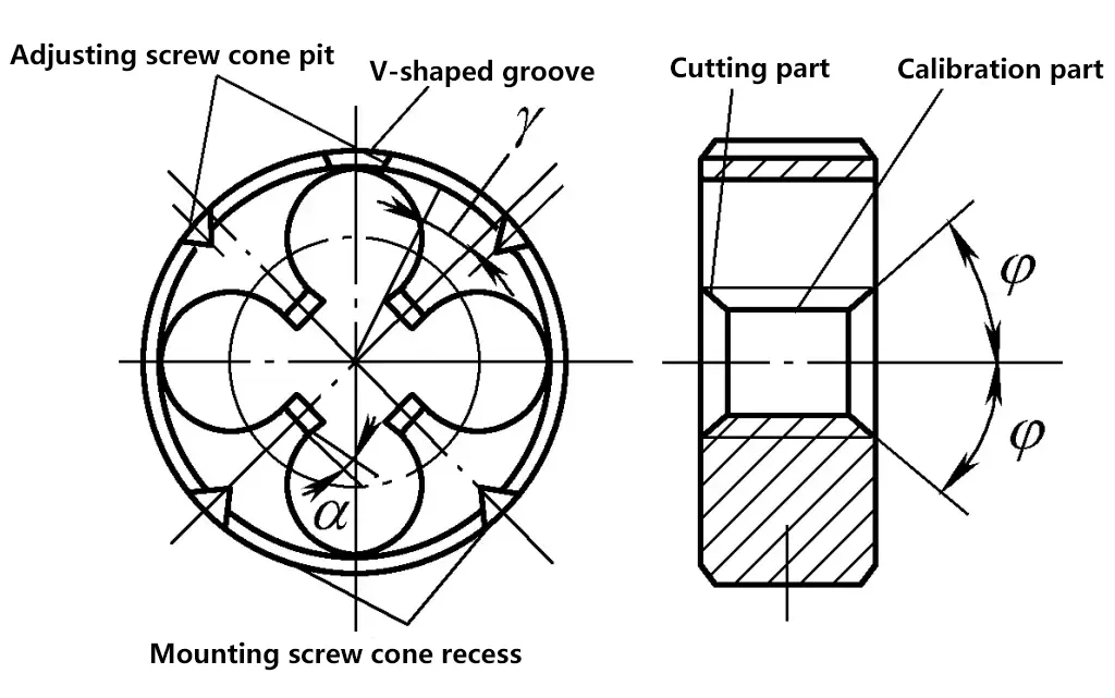
The shape of the circular die is similar to that of a nut, with several chip removal holes drilled near the major diameter of the thread to form cutting edges. The die consists of a cutting part and a calibrating part, and its structure is shown in Figure 6.
2. 55° Sealing Pipe Thread Die
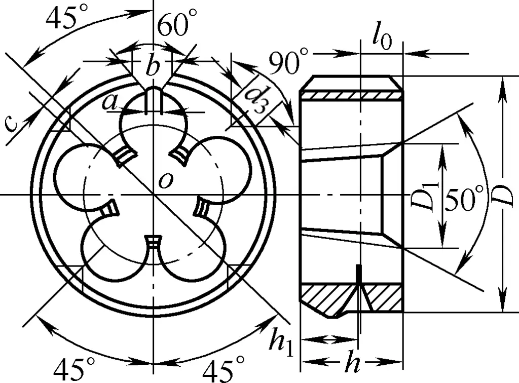
This die is specifically used for threading the tapered threads at the end of small-diameter pipes, as shown in Figure 7. The 55° sealing pipe thread die only has a cutting cone on one side and can only be used alone; other parts of its structure are similar to those of the circular die.
IV. Threading
Threads are usually made on cylindrical rods by manual operation, which is called manual threading.
1. Tools for Threading
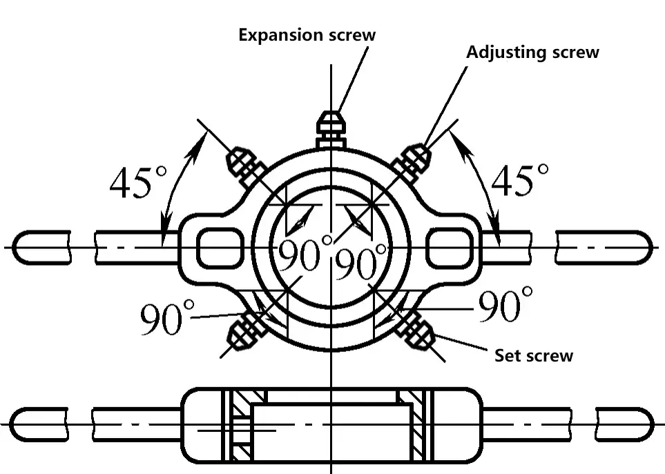
The main tool for manual threading is the circular die holder. The circular die holder is used to install the die, and its common structure is shown in Figure 8. During use, tighten the screw 8 and the set screw to firmly secure the die in the holder.
2. Determining the Diameter of the Round Rod Before Threading
Just like tapping threads with a tap, when using a circular die for threading on a workpiece, the material deforms due to compression, and the thread crest will be slightly raised. Therefore, the diameter of the round rod before threading should be slightly smaller than the major diameter of the thread. Generally, the diameter of the round rod is calculated using the following formula:
d0=d-0.13P
In the formula:
- d0 – Re-calculated diameter of round rod before threading (mm);
- d – Major diameter of the thread (mm);
- P – Thread pitch (mm).
The diameter of the round rod before threading can also be determined according to Table 3.
Table 3 Diameter of the Rod When Threading with a Die
| Coarse Thread Metric | Inch Thread | 55° Non-Sealing Pipe Thread | |||||||
| Thread Diameter d/mm | Thread Pitch P/mm | Round Rod Diameter d0/mm | Thread Diameter /in① | Round Rod Diameter d0/mm | Thread Diameter /in① | Pipe Outer Diameter d0/mm | |||
| Minimum Diameter | Maximum Diameter | Minimum Diameter | Maximum Diameter | Minimum Diameter | Maximum Diameter | ||||
| M6 | 1 | 5.8 | 5.9 | 1/4 | 5.9 | 6 | 1/8 | 9.4 | 9.5 |
| M8 | 125 | 7.8 | 7.9 | 5/16 | 7.4 | 7.6 | 1/4 | 12.7 | 13 |
| M10 | 1.5 | 9.75 | 9.85 | 3/8 | 9 | 9.2 | 3/8 | 16.2 | 16.5 |
| M12 | 1.75 | 11.75 | 11.9 | 1/2 | 12 | 12.2 | 1/2 | 20.5 | 20.8 |
| M14 | 2 | 13.7 | 13.85 | — | — | — | 5/8 | 22.5 | 22.8 |
| M16 | 2 | 15.7 | 15.85 | 5/8 | 15.2 | 15.4 | 3/4 | 26 | 26.3 |
| M18 | 2.5 | 17.7 | 17.85 | — | — | — | 7/8 | 29.8 | 30.1 |
| M20 | 2.5 | 19.7 | 19.85 | 3/4 | 18.3 | 18.5 | 1 | 32.8 | 33.1 |
| M22 | 2.5 | 21.7 | 21.85 | 7/8 | 21.4 | 21.6 | 1.125 | 37.4 | 37.7 |
| M24 | 3 | 23.65 | 23.8 | 1 | 24.5 | 24.8 | 1.25 | 41.4 | 41.7 |
| M27 | 3 | 26.65 | 26.8 | 1.25 | 30.7 | 31 | 1.875 | 43.8 | 44.1 |
| M30 | 3.5 | 29.6 | 29.8 | — | — | — | 1.5 | 47.3 | 47.6 |
| M36 | 4 | 35.6 | 35.8 | 1.5 | 37 | 37.3 | |||
| M42 | 4.5 | 41.55 | 41.75 | ||||||
| M48 | 5 | 47.5 | 47.7 | ||||||
| M52 | 5 | 51.5 | 51.7 | ||||||
| M60 | 5.5 | 59.45 | 59.7 | ||||||
① in is a non-legal measurement unit, 1in = 25.4mm.
3. Key Points of Manual Threading Operation
The main methods and key points of manual threading operation are as follows:
1) Before threading, the end of the round rod should be chamfered at an angle of 15°~20°, as shown in Figure 9. The minimum diameter of the top end should be smaller than the minor diameter of the thread, making it easier for the die to align and cut in.
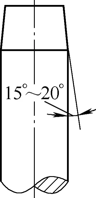
2) When threading, the cutting torque is very large, and the threaded part of the round rod should be close to the jaw. When clamping, use hardwood or thick copper plate as jaw pads to clamp the round rod, ensuring it is tight without damaging the surface of the round rod.
3) When threading, the die face should be perpendicular to the axis of the round rod. Press the die with the left palm and rotate the die holder with the right hand. Once the die has started threading the round rod, stop applying force and just rotate evenly. To break the chips, reverse frequently. Use cutting fluid when threading steel rods to improve the surface finish of the threads and prolong the life of the die.

