1. Spot Welding Equipment
The difference between TIG spot welding equipment and general TG equipment is that it has special control devices and spot welding guns. The control device can automatically ensure the advance delivery of argon, ventilation, and arc initiation, as well as welding time control, automatic current decay, and delayed shutdown of argon gas.
By adding a welding time controller and replacing the nozzle in ordinary manual tungsten argon arc welding equipment, it can also act as tungsten argon arc spot welding equipment.
2. Spot Welding Working Principle, Characteristics, and Application Range
Spot welding working principle
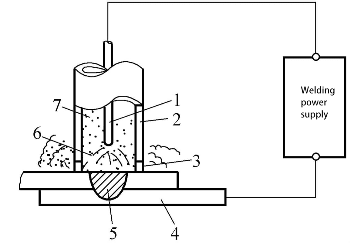
As shown in Figure 5-68, the nozzle of the welding gun is pressed tightly on the workpiece, using high-frequency arc initiation or induction arc initiation to first cause a small arc of about 5A between the tungsten and the nozzle. Then the welding current is turned on to form a welding arc for spot welding.
During welding, direct current positive connection can be used, or alternating current power supply with arc stabilization device can be used. Usually, direct current positive connection is used because it can obtain greater penetration depth, use smaller welding current (or shorter time), thereby reducing thermal deformation and other thermal effects.
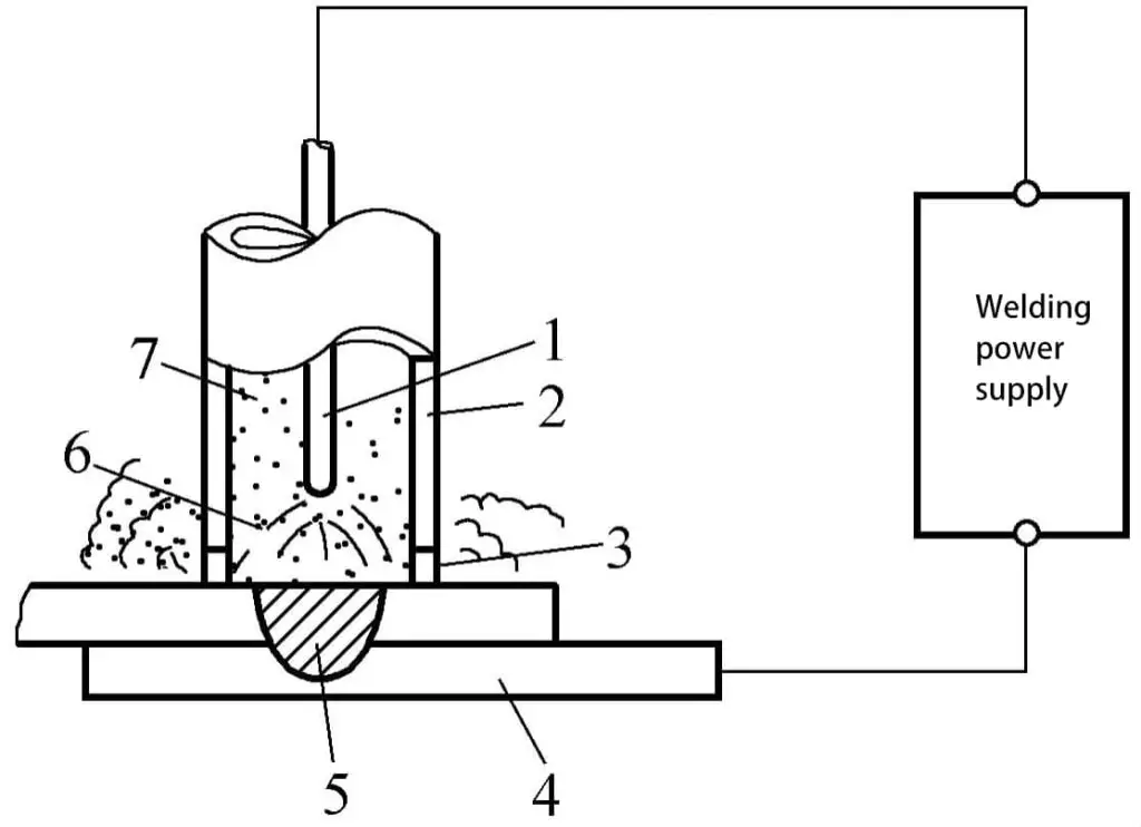
1—Tungsten 2—Nozzle 3—Vent hole 4—Base material 5—Weld spot 6—Arc 7—Argon gas
Characteristics of spot welding
The strength of the weld spot can be adjusted within a wide range, and the size of the weld spot is easy to control. When the welding time and welding current increase, the diameter of the weld spot increases, and the strength improves, which is convenient for multi-layer spot welding and spot welding of workpieces with varying thicknesses, especially for workpieces that cannot be clamped on the back.
Tungsten argon arc spot welding shows unique advantages. These advantages are compared with resistance welding. Its disadvantage is that its productivity is not as high as resistance welding.
Application range
Suitable for welding various thin plate structures and connections between thin plates and thicker materials, mainly welding materials such as stainless steel and low alloy steel.
3. Key Points of the Process
The cleaning requirements for tungsten electrode argon arc spot welding are the same as those for general argon arc welding. Table 5-98 lists the welding parameters for 12Cr18Ni9 tungsten electrode argon arc spot welding.
Table 5-98 Welding Parameters for 12Cr18Ni9 Tungsten Electrode Argon Arc Spot Welding
| Material Thickness /mm | Welding Current /A | Welding Time /s | Secondary Pulse Current /A | Secondary Pulse Time /s | Shielding Gas Flow Rate /(L/min) | Weld Spot Diameter /mm |
| 0.5+0.5 | 80 | 1.03 | 80 | 0.57 | 7.5 | 4.5 |
| 0.5+0.5 | 100 | 1.03 | 100 | 0.57 | 7.5 | 5.5 |
| 2+2 | 160 | 9 | 300 | 0.47 | 7.5 | 8 |
| 2+2 | 190 | 7.5 | 180 | 0.57 | 7.5 | 9 |
| 3+3 | 180 | 18 | 280 | 0.69 | 7.5 | 10 |
| 3+3 | 160 | 18 | 280 | 0.69 | 7.5 | 11 |
Note:
1. The arc extinguishes for a period before adding secondary pulse current.
2. Arc length 0.5~1.0mm.
To fill the spot welding arc pit and increase the reinforcement, an appropriate amount of filler wire can be fed into the molten pool during welding. To improve crack resistance and reduce the tendency for cracking, the welding machine should have automatic current decay control, and a secondary pulse heating method can also be adopted.
4. Hot Wire TIG Welding
The hot wire tungsten electrode argon arc welding machine consists of a DC argon arc welding power source, an additional power source for preheating the welding wire (usually AC), a wire feeding mechanism, and a control circuit that coordinates these three parts. To achieve a stable welding process, the main power source can also use a low-frequency pulse power source.
Figure 5-69 is a schematic diagram of hot wire tungsten electrode argon arc welding. Before the welding wire is fed into the molten pool, it is heated by its own electrical resistance. About 10cm before entering the molten pool, a conductive clamp is set to introduce current to preheat the welding wire.
It is best to use an AC power source for the preheating current, as AC can reduce the magnetic bias blow to the arc formation. If the preheating current does not exceed 60% of the welding current, the arc’s longitudinal swing along the weld seam is within 30°.
To achieve sufficient preheating temperature, with limited preheating current, it is necessary to ensure that the welding wire has enough resistance within the preheating length, which is generally only about 10cm, so the diameter of the filler wire should not be too large, requiring a diameter of less than 1.2mm.
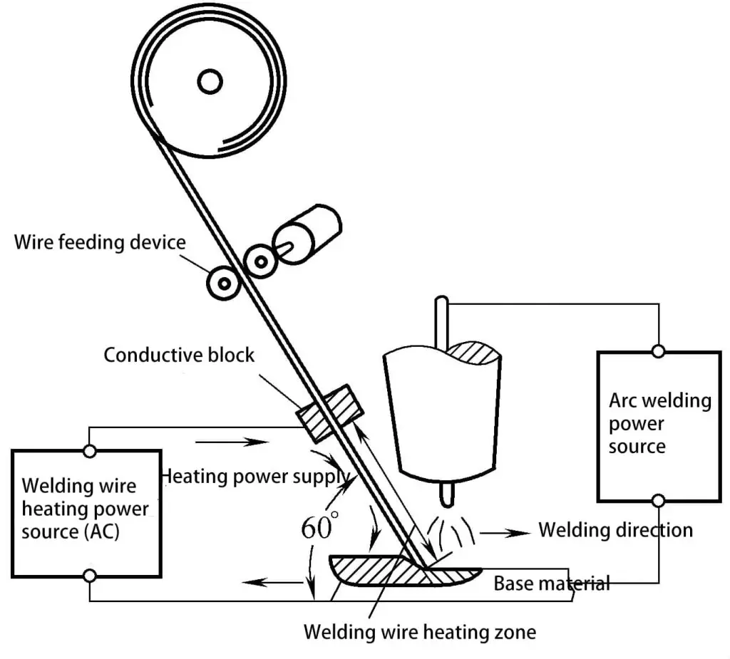
Hot wire welding has been successfully used for carbon steel, low alloy steel, stainless steel, nickel, and titanium alloys. For aluminum and copper, due to their low resistivity, a very large heating current is required, which causes excessive magnetic bias blow and uneven melting, so hot wire welding is not recommended.

