Hydraulic Press Brake vs. Folding Machine: A Comprehensive Guide
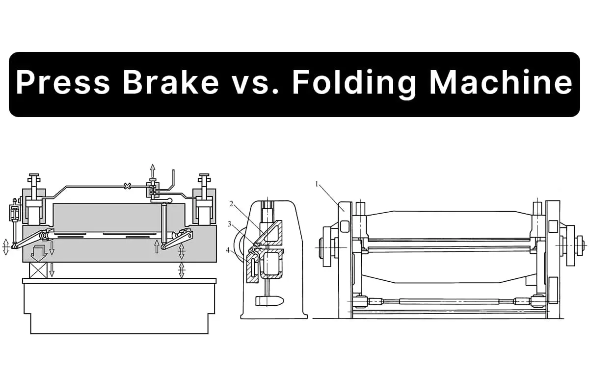
I. Overview 1. Process Introduction and Drive Mode The press brake is a processing machinery that bends metal sheets into [...]

The weld joint, commonly referred to as the joint, is formed by connecting two or more workpieces or parts using welding methods. Taking the fusion weld joint as an example, it consists of weld metal, fusion zone, and heat-affected zone, as shown in Figure 2-8.
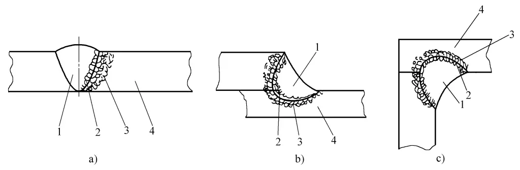
a) Butt joint
b) Lap joint
c) Corner joint
1—Weld metal
2—Fusion zone
3—Heat-affected zone
4—Base material
The functions of welded joints can be roughly divided into the following three types:
It can transfer the acting force in the welded structure from one part to another. Strength calculations must be performed on working joints to ensure they are safe and reliable.
It connects two or more parts into a whole to maintain their relative positions. Although the welds connecting these joints sometimes participate in force transmission or bear some acting forces, their main function is connection, so strength calculations are usually not performed for these joints.
Through welding, it ensures the airtightness or watertightness of the structure, and preventing leaks is its main task. Sealing joints can also be working joints or connecting joints.
Welded joints are connecting elements between structural components, and they also transmit and bear structural forces. They are classified according to their role in the structure, welding methods, and joint structural forms as follows:
1) Contact weld: The weld does not transmit or transmits very little load, serving only as a connection.
2) Load-bearing weld: The weld and the workpiece being welded are in series, transmitting the entire load.
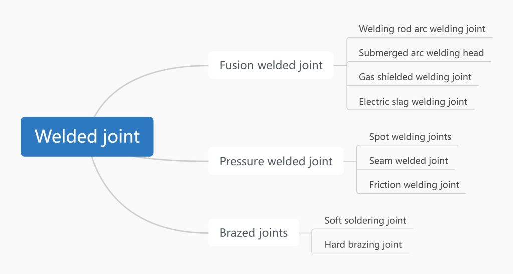
Includes fusion welded joints, pressure welded joints, brazed joints, etc., classified as shown in Figure 2-9.
Based on the structural form of the joint, there are ten types: butt joint, T-joint, cross joint, lap joint, corner joint, end joint, sleeve joint, skewed butt joint, flanged joint, and locked butt joint, as shown in Figure 2-10.
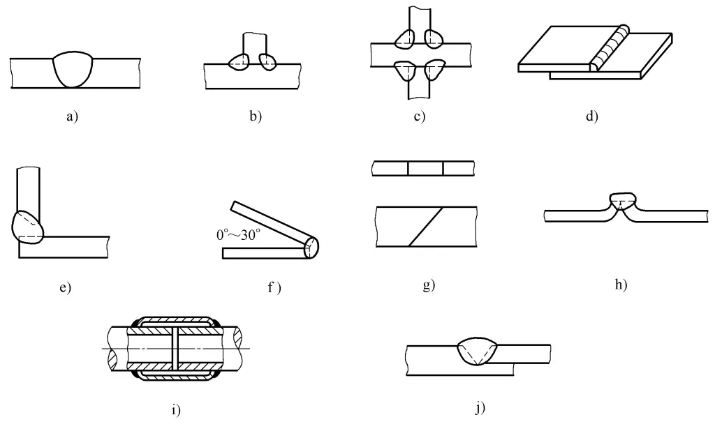
a) Butt joint
b) T-joint
c) Tenon joint
d) Lap joint
e) Corner joint
f) End joint
g) Bevel butt joint
h) Flanged joint
i) Sleeve joint
j) Locked bottom butt joint
Butt joints are used to weld two workpieces on the same plane relative to each other, forming a joint that has better stress conditions, less stress concentration, consumes less welding material, and has less welding deformation. Therefore, butt joints are a relatively ideal form of joint. To ensure welding quality, bevel butt welding is often performed, as shown in Figure 2-11.
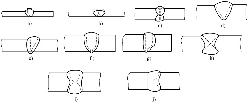
a) Single-sided flange
b) Double-sided flange
c) I-shape
d) V-shape
e) Single-sided V-shape
f) U-shape with blunt edge
g) J-shape with blunt edge
h) Double V-shape
i) With blunt edge double U-shape
j) With blunt edge double J-shape
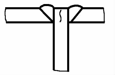
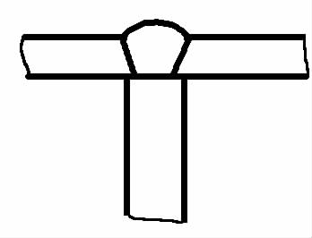
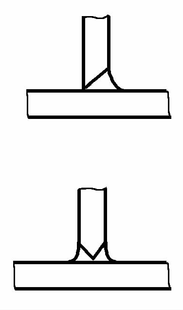
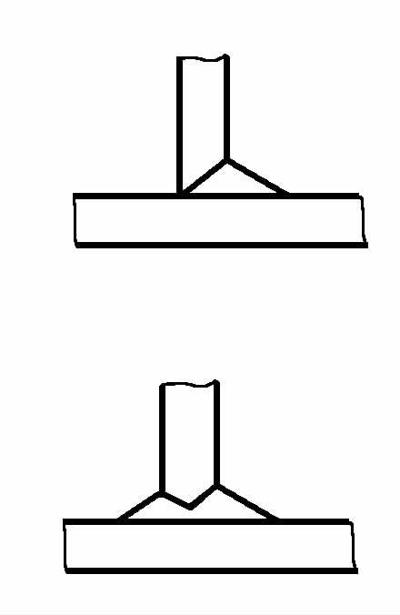
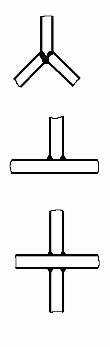
T-shape and cross joints are joints that connect workpieces perpendicular to each other using fillet welds, which is a typical type of arc welding joint. T-shape and cross joints can be either fully penetrated or not. Joints without a groove are usually not fully penetrated, and whether grooved joints are fully penetrated depends on the shape and size of the groove.
Grooved joints that are fully penetrated have a stronger ability to withstand dynamic loads, and their strength can be calculated as butt joints. T-shape and cross joints are shown in Figure 2-12.
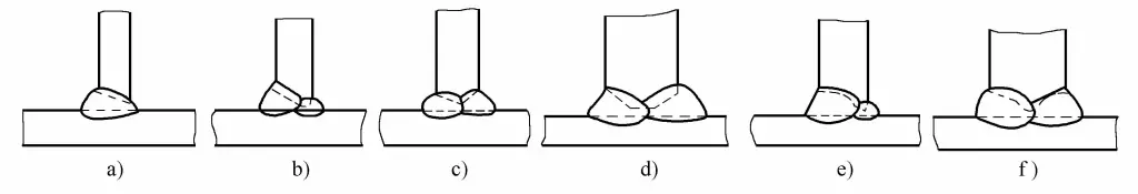
a) Single-side V-shape
b) With blunt edge single-side V-shape
c) Double single-side V-shape
d) With blunt edge double single-side V-shape
e) With blunt edge J-shape
f) With blunt edge double J-shape
A lap joint is a joint that connects two workpieces by overlapping them partially or adding a special lap piece using fillet welds, plug welds, or groove welds. Lap joints are widely used due to the simplicity of pre-weld preparation and assembly, and their common forms are shown in Figure 2-13.
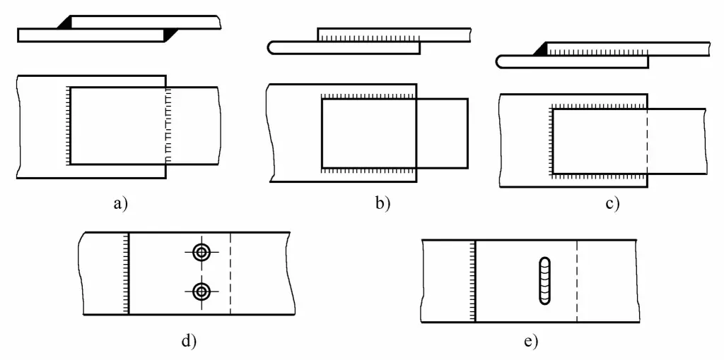
a) Front fillet weld connection
b) Side fillet weld connection
c) Combined fillet weld connection
d) Front fillet weld + plug weld connection
e) Front fillet weld + groove weld connection
A corner joint is a joint where the end faces of two workpieces to be welded form an angle greater than 30° and less than 135°. Corner joints are commonly used on box-shaped components, and common connection forms are shown in Figure 2-14.

a) Single-sided corner weld without groove
b) Double-sided corner weld without groove
c) Grooved through-corner joint
Every weld on a welded structure should be easily accessible for welding; therefore, it is necessary to ensure that there is space around the weld for the welder to operate freely and for the welding equipment to function normally. A brief introduction to the welding conditions required for various welding methods is as follows.
(1) Shielded metal arc welding
When using shielded metal arc welding, it is necessary to ensure that the welder can approach the weld, see the welding part clearly during the operation, and move the electrode conveniently. The welder should try to weld in a normal posture.
For example, Figure 2-15 shows a welded structure composed of various profiles. The welds indicated by the arrows in the figure cannot be welded and should be designed as the structure in the middle or on the right of the figure.
a) Unreasonable
b) Improved
c) Best
Figure 2-16 shows reasonable and unreasonable designs of various arc welding joints. In Figure 2-16a~e, the sharp angles indicated by the arrows are difficult to weld; change to the reasonable design on the right to avoid forming sharp angles; Figure 2-16f shows a butt joint, the top one is an unreasonable design, change to the bottom one with increased joint gap for a reasonable design, avoiding the possibility of not being able to weld.
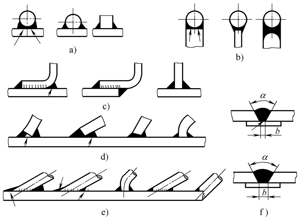
Figure 2-17a shows a structure with two or more parallel T-joints. To ensure the quality of the corner welds of this structure, it is necessary to consider the distance B and height H between the two vertical plates to ensure that the electrode can be tilted at a certain angle α and have space for movement. The tilt angle α is related to the thickness of the flat plate and the vertical plate.
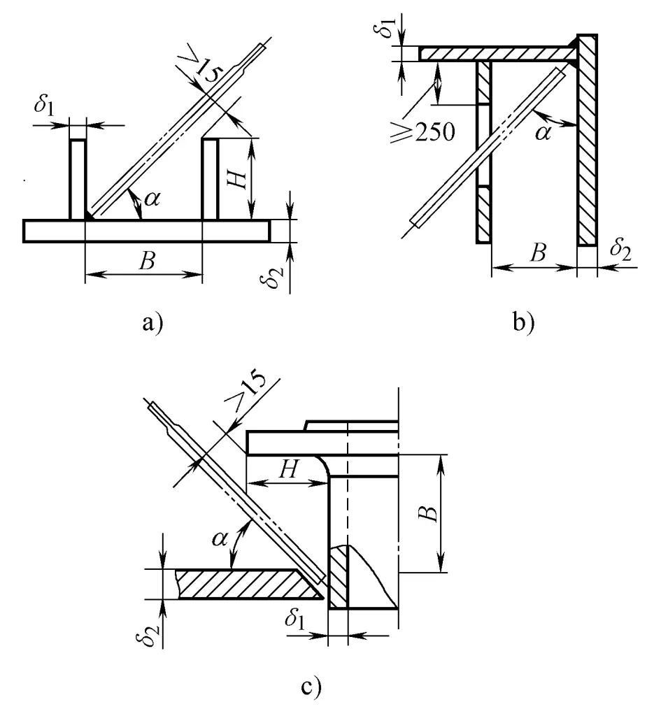
(When B≤400mm, δ0 < δ1, α>45°; δ2 = δ3, α=45°; δ2 > δ2, α<45° When B>400mm, H is not limited)
Figure 2-17b starts the process hole to ensure the internal weld seam is accessible. Figure 2-17c is the operating space required for welding the annular corner joint between the flange nozzle and the cylinder on a cylindrical vessel.
Figure 2-18 is an oblique T-joint. The space on the side where the θ angle is less than 90° is small, making observation and handling difficult. Therefore, the θ angle should not be too small in various welding positions.

(For flat welding, θ≥60°; for vertical welding, θ≥70°; for overhead welding, θ≥80°)
For enclosed welding structures, there are the following two cases.
1) Structures where welding cannot be performed inside.
It should be designed as a single-sided welded joint, usually using a single-sided bevel weld form. To prevent burn-through, a permanent backing plate can be placed on the backside, as shown in Figures 2-19a and b. For different plate thicknesses, a V-shaped bevel joint with a locking edge can be designed, as shown in Figure 2-19c.

a) Butt joint with backing plate
b) T-shaped joint with spacer
c) Locked butt joint
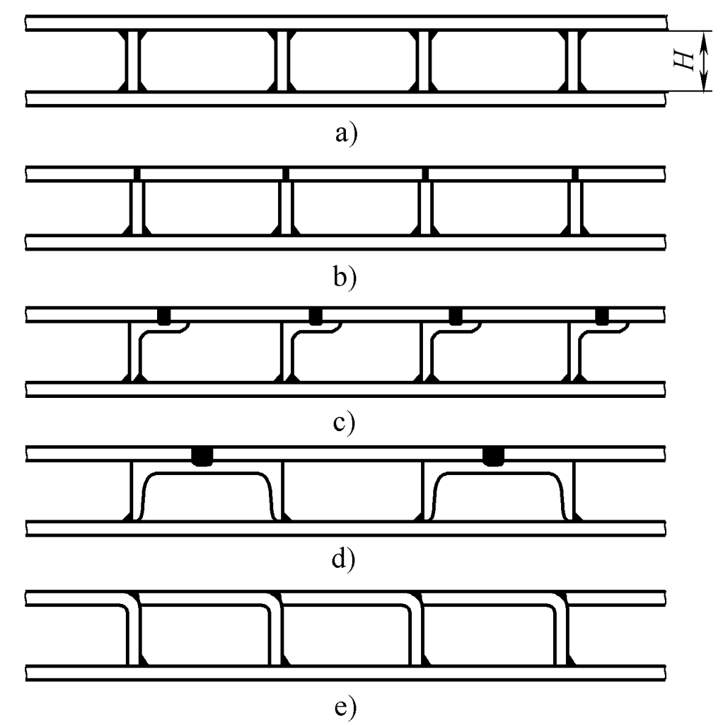
Figure 2-20a shows a double-wall structure with ribs, which cannot be welded due to the small size H. If changed to the structures b, c, d, e in Figure 2-20, the upper wall plate and ribs can be completed from the outside through butt welding, plug welding, or groove welding.
Some welded structures can utilize the structure’s own lightening holes to achieve internal welds. For example, the two circumferential seams inside the double-web plate welded gear body, as shown in Figure 2-21.

When the joint must be welded from both sides and there are no available lightening holes, technological holes can be opened at non-critical positions for welding internal seams, and then sealed after welding is completed, as shown in Figure 2-22. For the size of the technological holes, refer to Figure 2-22b, which can be made into slot-shaped or round holes, but ensure that there is a distance of about 250mm from the center of the hole to the welding part.
a) Application examples
b) Shape and size of technological holes
2) Structures that can be welded inside.
Due to poor welding conditions inside the structure, it is necessary to minimize the amount of welding work inside, such as using an asymmetric bevel that is shallow inside and deep outside, and increasing the internal operating space as much as possible to reduce the concentration of smoke, etc. The minimum space dimensions for welding inside an empty box are shown in Table 2-1.
Table 2-1 Welding operation space inside an empty box (unit: mm)
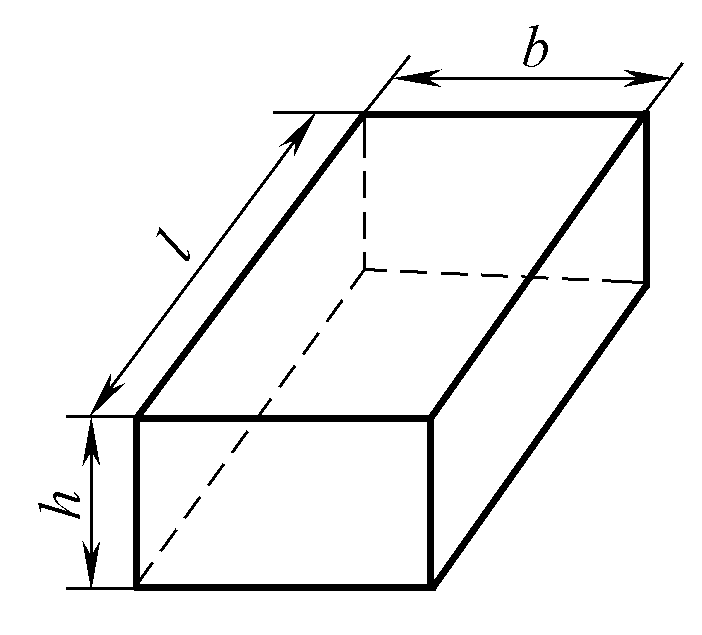 | l | 500 | 800 | 900 | 1200 | 1200 |
| hxb | 300 ×400 | 400 ×300 | 400 × 600 | 600×400 | 500 ×600 |
As the length l increases, the width b and height h should be appropriately increased. A reasonable assembly order should also be adopted, welding all internal welds before forming a closed structure, and then installing the last remaining part and sealing it from the outside.
(2) Submerged arc welding
Its characteristic is that it is most suitable for welding straight long welds and circular welds in a horizontal (downward) position, and it requires necessary auxiliary devices to cooperate. Therefore, when designing submerged arc welding joints, consider the relative motion space between the submerged arc welding head and the workpiece, as well as the location where corresponding auxiliary devices can be placed.
(3) CO2 gas shielded welding
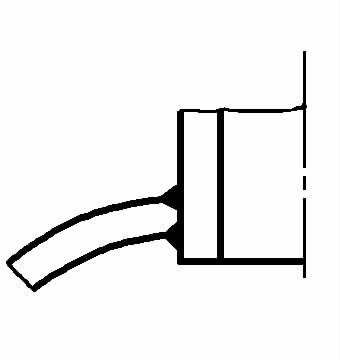
When designing structures for CO2 welding, consider that the welding gun must have the correct operating position and space to ensure good weld formation. The position of the welding gun is determined based on the form of the weld, the shape and size of the welding gun (such as the external dimensions of the nozzle), the protrusion length of the welding wire, and the size of the bevel angle α. The required welding gun positions for several joints are shown in Figure 2-23.

a) Fillet weld
b) V-shaped or U-shaped groove butt joint flat welding
c) Narrow gap butt joint flat welding
d) J-shaped groove butt joint flat welding α—groove angle θ—welding gun tilt angle
Welds on welded structures that require quality inspection must have conditions suitable for flaw detection, with different flaw detection methods having corresponding requirements, see Table 2-2.
Table 2-2 Conditions required for various flaw detection methods
| Flaw detection methods | Requirements for the spatial position of flaw detection | Requirements for the detection surface | Requirements for the back of the detection area |
| Ray flaw detection | Requires a large spatial position to accommodate the placement of the ray head and the adjustment of the focal length | Surface does not need machining, only needs to remove things that affect the display of defects; there should be a place for placing lead numbers, lead arrows, and densitometers | Can place a dark box |
| Ultrasonic flaw detection | Requires a smaller space, only needs to place the probe and the space for the probe to move | There should be a surface range for the probe movement, surface machining should be done as much as possible to facilitate acoustic coupling | When using the reflection method for flaw detection, the backside requires a good reflective surface |
| Magnetic particle inspection | Requires a spatial position for magnetizing the inspection area to spread magnetic powder and observe defects | Remove oxides and other contaminants that affect the accumulation of magnetic particles, and ensure there is space for the probe to work | — |
| Penetrant testing | Space is required for applying penetrant and observing defects | Surface contaminants must be removed | If using kerosene for testing, space is required on the back for applying kerosene, and contaminants that hinder the penetration of kerosene must be removed |
(1) Suitable for radiographic testing of welded joints
Currently, radiography with photographic methods is widely used in X-ray testing. To obtain certain penetration capabilities and improve the clarity of defect images on the film, the focal distance for medium-thick plates is adjusted within a range of 400~700mm. Based on this, the distance from the testing machine head to the detection surface of the weldment can be determined, leaving operational space around the weld.
Before testing, it is also necessary to choose the direction of exposure based on the geometric shape and joint type of the weldment, and correctly place the dark box (attach the film) in this direction.
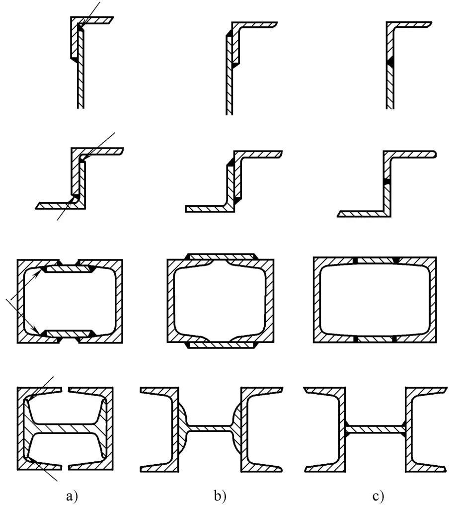
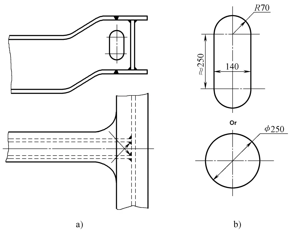
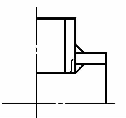
Generally speaking, butt joints are most suitable for radiographic testing, and can be completed with a single exposure. T-joints and corner joints often require multiple exposures from different directions to avoid missing defects. The correct selection of various fusion welded joints for radiographic testing is shown in Figure 2-24. Among them, Figure 2-24a is an insert-type corner joint, where the weld cannot be laid flat or bent when placing the film.
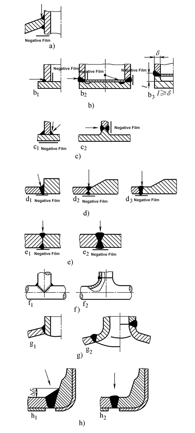
Figure 2-24b shows the connection joint between the base and the simplified body. Figure 2-24b 1 and Figure 2-24b 2 are not suitable for radiographic inspection, only Figure 2-24b 3 is suitable for radiographic inspection. Figure 2-24c shows a T-joint, where Figure 2-24c 1 is not suitable for radiographic inspection, and Figure 2-24c 2 can only be inspected using radiography through a substitute part (forging or casting, processed by cutting).
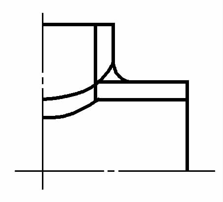
The transition in Figure 2-24d 1 is too abrupt, making inspection difficult; the transition in Figure 2-24d 2 is smoother, but local differences in wall thickness still affect the inspection; moving the joint in Figure 2-24d 3 outside the transition area is most suitable for radiographic inspection. Figure 2-24e 1 shows an unfused butt weld, which cannot be inspected by radiography, only Figure 2-4e 2 can be inspected.
The joint design in Figure 2-24f 2 facilitates radiographic inspection. Due to thickness differences and spatial curvature, Figure 2-24g 1 is not suitable for radiographic inspection, changing to the joint form of Figure 2-24g 2 makes inspection much easier. The corner joint in Figure 2-24h, if changed to a butt joint, can be completely inspected by radiography.
(2) Weld joints suitable for ultrasonic inspection
To sensitively detect various defects within the weld joint during ultrasonic inspection, the probe should have sufficient movement area. The movement area of the probe for ultrasonic inspection of butt joints is shown in Figure 2-25. The size of the probe movement area is determined by the formula in Table 2-3.

Table 2-3 Determination of probe movement area size
| Plate thickness range/mm | Formula for calculating the size of the probe movement area | Explanation |
| 8~46 | l ≥ 2δK + L | Flaw detection surface on both sides of the inner or outer wall weld |
| >46 ~ 120 | l≥δK +L | Flaw detection surface on both sides of the inner and outer wall welds |
Note: l—probe movement area size in mm; δ—thickness of the object being inspected, in mm; L—probe length, generally 50mm; K—tangent value of the refractive angle β of the angled probe, which can be determined by the plate thickness, for thicknesses of 8 to 25mm, k=2.0 to 3.0; for thicknesses of 25 to 46mm, K=1.5 to 2.5; for thicknesses of 46 to 120mm, k=1.0 to 2.0.
The probe movement area for ultrasonic flaw detection of butt joint welds of different thicknesses is shown in Figure 2-26. The minimum size of the probe movement area l is determined by the formula in Table 2-4.
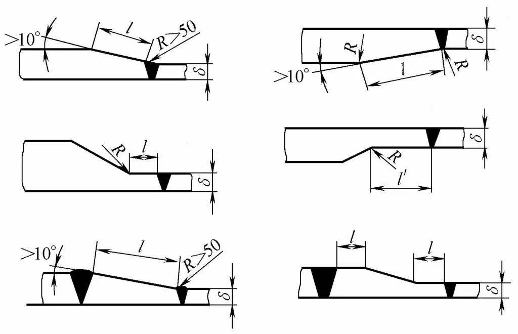
Table 2-4 Minimum size of the probe movement area for ultrasonic flaw detection of butt joint welds of different thicknesses
| Plate thickness /mm | 10≤δ<20 | 20≤δ<40 | δ≥40 | |
| Probe refractive angle / (°) | 70 | 60 | 45 ,60 | |
| Probe movement area /mm | lExterior | 5.5δ +30 | 3.5δ + 30 | 3.5δ +50 |
| lInterior | 0.7 lExterior | 0.7 lExterior | 0.7 lExterior | |
The probe movement area for ultrasonic flaw detection of welded joints of pressure vessel cylinders is shown in Figure 2-27, with the minimum size shown in Table 2-5.

Table 2-5 Minimum size of ultrasonic testing probe movement area for pressure vessel cylinder welds
| Plate thickness δ/mm | R+l | l | la |
| ≤40 | 1.5δ | 1.0δ | 3δ |
| >40 | 1.0δ | 0.7δ | 2δ |
When corrosive media directly contact the metal surface, intense localized corrosion often occurs in crevices and sharp corners. This is caused by the accumulation of stagnant liquids and sediments in these areas. This type of corrosion is called crevice corrosion.
Methods to prevent and reduce crevice corrosion include the following:
1) Preferably use butt welding, with complete penetration of the weld, and do not use joints with single-sided root penetration.
2) Avoid joint crevices and sharp corners, ensure that liquid media can be completely drained and easily cleaned, and prevent the deposition of solid materials at the bottom of the structure.
3) To avoid crevice corrosion, minimize the use of intermittent welding, single-sided welding, lap welding, and incomplete penetration, and seal unavoidable weld crevices as shown in Figure 2-28.
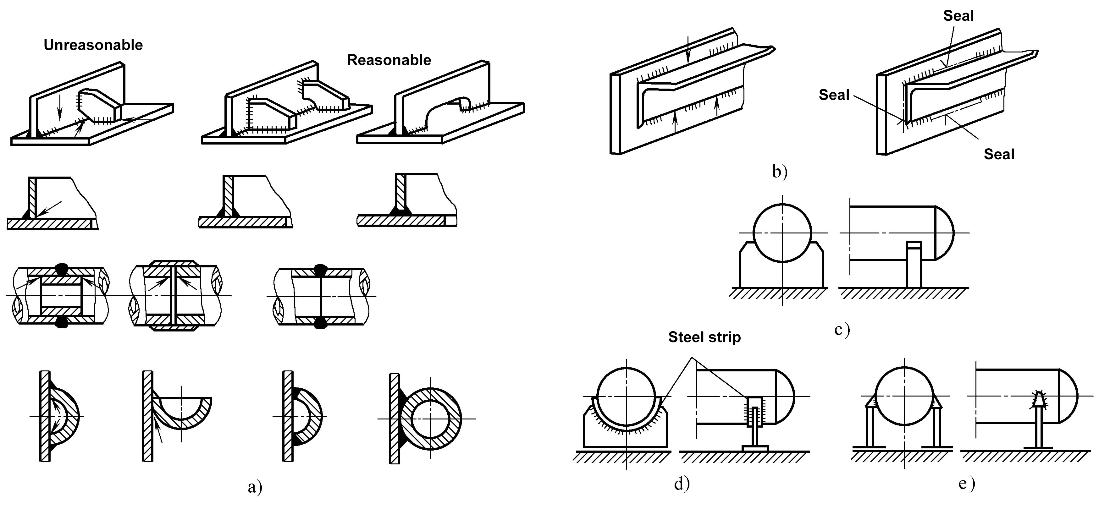
a) Avoid gaps caused by intermittent welding, single-sided welding, lap welding, and incomplete penetration (indicated by arrows)
b) Sealing of un-welded intermittent welds
c) Gaps formed between loosely placed containers and saddle racks
d) Add steel strip welding
e) Four-point welding brackets can reduce the bearing surface
For the welding structure of large or heavy machinery, rolled steel plates ranging from 30 to 100mm or even thicker are often used to form welding structures. Special attention should be paid to preventing lamellar tearing.
Lamellar tearing mainly occurs in the heat-affected zone or the base metal away from the heat-affected zone of corner weld joints, T-joints, and cross joints. To prevent lamellar tearing, it is necessary to reduce or avoid restraint stress or strain in the thickness direction of the steel plate from the structure, and choose a reasonable joint form, see Table 2-6.
Table 2-6 Joint forms to prevent lamellar tearing
| Joints prone to lamellar tearing | Improvable joint | Description |
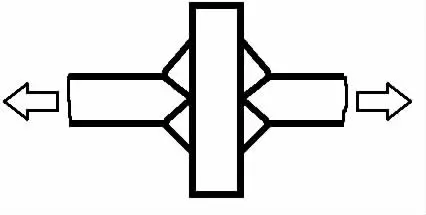 |  | The direction indicated by the arrow is the direction in which restraint stress may occur during welding, or the direction of force when the component is in operation |
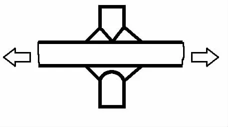
 |  | Reduce the shrinkage stress in the thickness direction by opening a groove or changing the shape of the weld, generally open a groove on the side that bears the stress in the thickness direction |
 |  | Avoid the effect of weld shrinkage force in the plate thickness direction |
 |  | Reduce the restraint stress of the nozzle in the plate thickness direction |
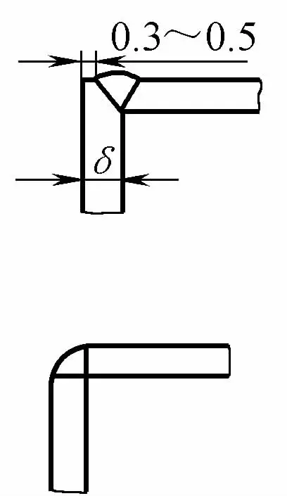
 |  | Under the premise of ensuring full penetration, the groove angle should be as small as possible, and without increasing the groove angle, increase the size of the weld toe as much as possible to increase the weld force area and reduce the stress value in the thickness direction |
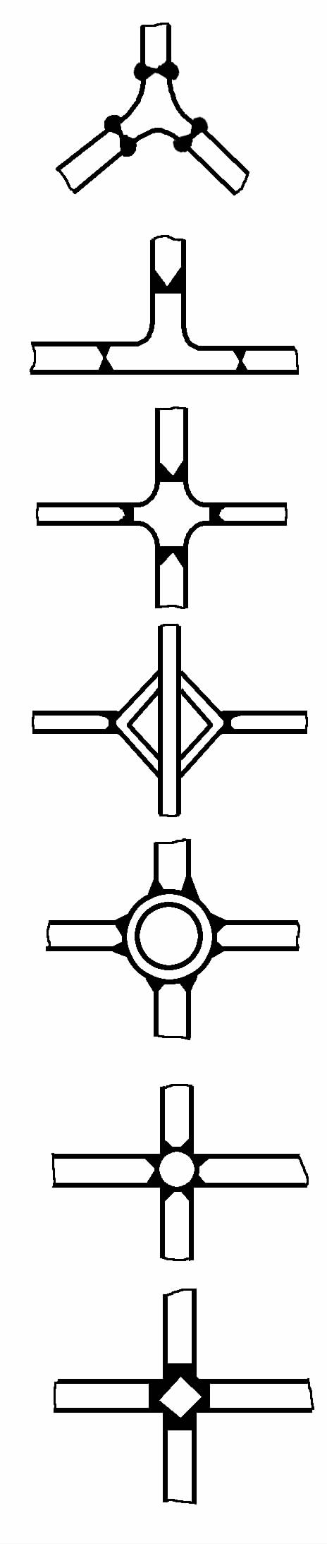 |  | Inserts without lamellar tearing, usually using rolled profiles. Improved joint form, which avoids lamellar tearing and also avoids overly dense welds, reducing stress concentration |
 | 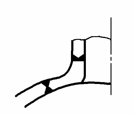 | This is the connection between the nozzle and the shell in the pressure vessel, using inserts for hole reinforcement in the joint, which can also reduce lamellar tearing and reduce stress concentration at the weld |
 | 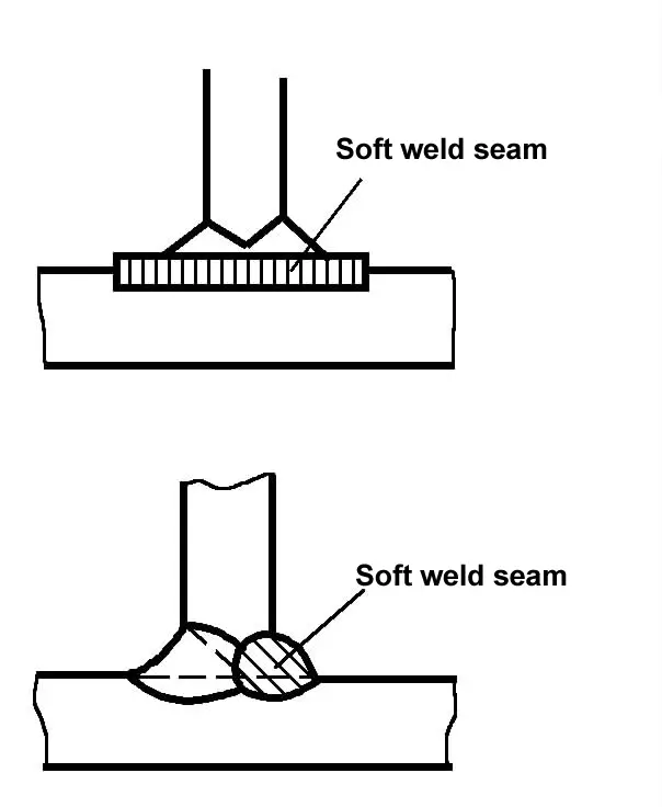 | Use soft welds with good plasticity to relieve the stress in the thickness direction of the base metal. The upper figure is a soft metal transition layer deposited on the surface to be welded; the lower figure is a soft metal weld on the side to be welded first |