1. Bending Springback
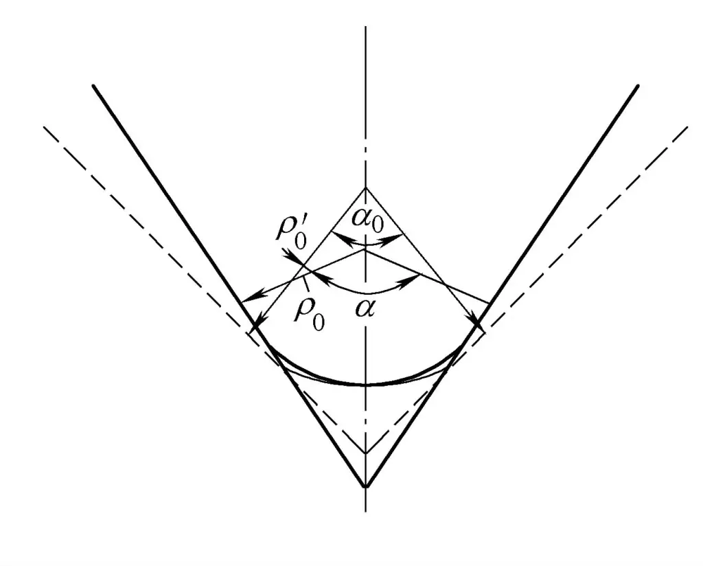
Like any form of plastic deformation, tube bending is accompanied by elastic deformation. When the load is removed, the fibers on the outer side of the bending neutral layer shorten due to elastic recovery, and the fibers on the inner side lengthen, thus changing the bending rate and bending angle. This phenomenon is known as springback. There are two forms of springback, as shown in Figure 4-25.

1) The curvature decreases.
The curvature decreases from 1/ρ0 before unloading to 1/ρ’0 after unloading.
2) The bending angle decreases.
The bending angle decreases from α before unloading to α 0 after unloading. The magnitude of springback can be calculated by the change in curvature ΔK or the change in bending angle Δα (also called springback angle).
Δα = α – α 0
(1) Factors affecting bending springback
In the bending process, there are many factors affecting the amount of springback, the main factors are as follows:
1) The mechanical properties of the blank.
The smaller the value of σs /E, that is, the smaller σs , and the larger the value of E, the smaller the springback value Δα.
2) The degree of deformation r/t.
Under the same conditions, the smaller the r/t, the greater the degree of bending deformation, the proportion of elastic deformation in the total deformation decreases, so the springback of bending decreases.
3) Bending central angle α.
The larger the bending central angle α, the longer the length of the deformation zone. Under the same deformation conditions, the amount of deformation per unit length decreases. Therefore, the larger the bending angle α, the proportion of elastic deformation in the total deformation will correspondingly increase, and the springback value Δa will be larger.
4) Die clearance Z.
Larger die clearance, larger springback.
5) Bending method.
The springback amount is small in the draw bending process, and the smallest in the push bending process.
6) Workpiece shape and material structure state.
Complex shapes, multiple mutual pulls result in small springback, large springback after cold work hardening.
7) Mold structure and the size of the pressing force.
The edge pressing force is large, resulting in a small rebound amount after the workpiece is bent.
(2) Determination of the rebound value
Determining the rebound value of the workpiece is to take corresponding measures to overcome the rebound, so that the bent workpiece can meet the accuracy requirements of the design pattern. The methods for determining the rebound value include the lookup chart method, the lookup table method, and the calculation method.
In actual bending forming, due to the existence of cross-sectional distortion and wrinkling problems, these problems will affect the rebound; on the other hand, it is difficult to accurately determine the neutral layer during the bending process of profiles, making the calculation of rebound more difficult. The rebound calculation of profile bending is much more complex than that of plate bending, so the methods for calculating the rebound of tube bending are all approximate and have a large difference from the actual situation.
At present, both domestically and internationally, research on rebound is still ongoing. Since rebound involves many factors and is quite complex, there is currently no accurate calculation formula. Therefore, the control of the rebound value is generally corrected using molds of different structures, mainly corrected during mold testing.
(3) Methods to reduce and prevent rebound
The methods to reduce and prevent rebound can be divided into two main categories from a principle perspective. The first category of methods ensures the shape of the part after rebound by increasing deformation. The main measures of this category are to correct the shape of the mold, reduce the bending curvature of the part, or increase the bending angle, so that the part after rebound meets the design requirements.
Another category of methods is to reduce rebound by changing the stress distribution of the bent deformed part. In this category, the most commonly used measure is to apply tangential tensile stress, making the stress distribution on the cross-section of the bent part uniform, thereby reducing the unevenness of elastic recovery during unloading and reducing the amount of rebound.
Rebound in bending forming is one of the main factors affecting the dimensional accuracy and production efficiency of parts. Since the prediction of rebound is closely related to the entire forming process, the rebound problem is quite complex and is a hot and difficult point in the research of profile bending forming. Many scholars at home and abroad have conducted in-depth research and discussion.
Currently, there are several methods for dealing with the problem of rebound in tube bending:
1) List the rebound data table based on experience.
For example, several domestic shipyards have purchased CNC pipe bending machines from the American WALLACE COAST company, which use experience data set in the control system for rebound compensation. However, due to the large error of this method, the bending accuracy of the CNC pipe bending machine is not ideal.
2) Use theoretical calculation methods.
Since the force situation during pipe bending is very complex, assumptions and simplifications need to be made during calculations, and the material properties and actual working conditions are difficult to predict, so far, no successful precedent of using rebound theoretical calculation formulas in practice has been found, and further discussion is needed.
3) In the aircraft and automobile manufacturing industries, the method represented by the American EATON LEONARD company has been used for many years.
This method believes that although there are many factors affecting the rebound of pipe bending, once the machine tool is adjusted, the process parameters (bending radius, bending speed, clamping force, etc.) are determined, and at this time, the relationship between the bending angle and the forming angle after rebound is measured under the condition of bending a batch of material pipes, thus the turning angle of the pipe bending machine arm and the forming angle of the pipe can be considered as a linear relationship.
The method is to bend the pipes at 125° and 22° on the pipe bending machine, and after the pipes are bent, place them on the CNC pipe shape measuring machine to measure their actual forming angles as 120° and 20°, establishing a straight line equation through two points can obtain the relationship between the turning angle of the pipe bending machine arm and the required forming angle of the pipe. This method has a good effect.
To solve the rebound problem of pipe bending, the following work has been carried out:
1) A large number of rebound experiments were conducted.
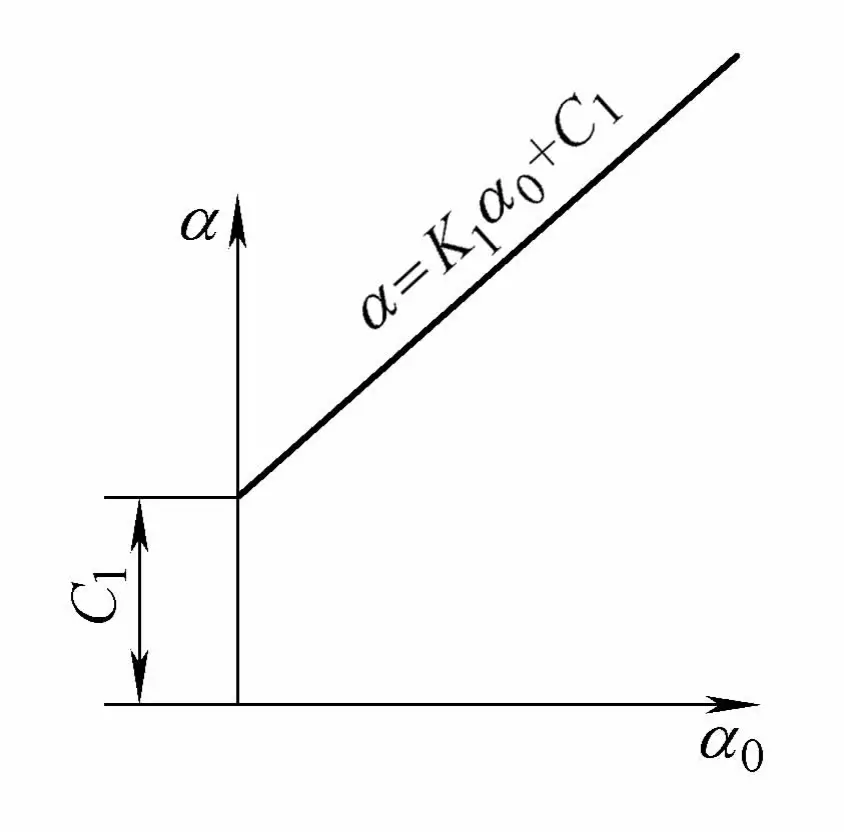
Through conducting coreless and cored pipe bending experiments of various specifications on multiple pipe bending machines, and performing regression analysis calculations on the measured data, it is known that the bending angle α and the forming angle α 0 change linearly, which is consistent with the theoretical calculation of linear change. However, differently, this line does not pass through the origin, there is a section distance C1 , as shown in Figure 4-26.
α = K1 α0 + C1
In the formula, K1 is the slope of a straight line;
C1 is the intercept of a straight line.

From the above formula, the following conclusion can be drawn: For tubes bent from the same batch of material, within the range of engineering bending angles, the relationship between the bending angle α and the forming angle α 0 is always a straight line that does not pass through the origin.
2) Theoretical analysis of tube bending springback experiment.
In order to analyze the correctness of the conclusions of the springback experiment, a force analysis was conducted for the working conditions of the tube bending machine, and after making some assumptions and simplifications, a large amount of calculations were performed.
The calculation results show that within a smaller range of bending angles, the relationship between the bending angle α and the forming angle α 0 is curved, and after the bending angle is greater than 1, the relationship between the bending angle α and the forming angle α 0 is linear, and it follows the same trend as the linear relationship observed during the experiment, thereby demonstrating the correctness of the springback experiment conclusions.
It should be noted that there is a significant difference between the two values, which is caused by the assumptions and simplifications made in the theoretical calculations and the fact that the actual tube bending conditions are much more complex than the calculated situations.
Therefore, the work mentioned above goes deeper than the research results represented by EATON LEONARD company, which considers “the relationship between the turning angle of the tube bending machine arm and the bending angle of the tube as linear”.
In summary, the best method currently for dealing with the problem of tube material bending springback is: when bending a batch of tube materials, two different bends (for example, 30° and 90°) experiments can be conducted on the given tube bending machine. During the experiment, record the two actual turning angles of the tube bending machine arm α1 , α2 , and measure the two forming angles of the tube α01 , α02 . Then calculate the coefficients using the formula below.
K1 = (α 2 – α 1 ) / (α 02 – α 01 )
C1 = α 1 – α 1 (α 2 – α 1 ) / (α 02 – α 01 )
By substituting the above two formulas into the formula for α in the rebound experiment, the linear equation obtained is the rebound rule for that batch of pipe material.
2. Bending elongation
After bending on a bending machine, the axial length of a pipe of a certain length will increase, a phenomenon known as bending elongation. The increase in axial length is called the elongation of the pipe. Bending elongation affects the dimensional accuracy of parts. The methods used in the past to solve this problem include:
1) An elongation data table based on experience was compiled for production use, but this method has a large error when used.
2) Calculation methods related to the theory of pipe bending elongation. Like rebound, there is currently no theoretical calculation formula that has been successfully used in practice, which still needs further discussion.
3) In the aircraft and automobile manufacturing industries, a method represented by EATON LEONARD company has been used for many years, that is, while measuring the rebound with a CNC tube profiler, the so-called arc constant is calculated using a formula, which is the material length used when the bending angle is 100°, and it is also considered that the elongation of the pipe is directly proportional to the forming angle.
To solve the elongation problem of pipe bending, the following work was carried out:
1) A large number of elongation experiments were conducted.
By conducting various specifications of coreless and cored bending experiments on multiple bending machines in five shipyards, and performing regression analysis calculations on the data obtained from each batch of materials, it is known that the elongation △L has a linear relationship with the forming angle α’ that does not pass through the origin. That is:
ΔL = K 2 α’+C 2
In the formula,
- K 2 – the slope of the line;
- C 2 – straight line.
Through regression analysis of the measured data, the correlation coefficient γ is between 0.97 and 0.99, showing a clear linear relationship. Therefore, the following conclusion can be drawn: For tubes of the same batch of materials, within the range of engineering bending angles, the elongation ΔL and the forming angle α’ have a linear relationship that does not pass through the origin.
2) Regression verification was also performed on the springback data tables from related shipyards.
It is known from empirical calculations that the elongation ΔL and the forming angle α’ also have a linear relationship, with the correlation coefficient γ being above 0.99, indicating a high linearity, but the intercept is generally small.
3) Theoretical analysis of the pipe bending elongation experiment.
To further prove the correctness of the conclusions of the elongation experiment, a force analysis was conducted for the pipe bending conditions of the pipe bender, and after making some assumptions and simplifications, a large amount of calculations were performed. The calculation results show that within a small bending angle range, the elongation ΔL and the forming angle α’ have a curved relationship; when the bending angle is greater than 3°, the elongation ΔL and the forming angle α’ have a linear relationship.
The linear relationship part of the theoretical analysis and the trend of the linear relationship during the experiment are the same, which proves the correctness of the conclusions of the pipe bending elongation experiment. It should be noted that there is a significant difference in the values between the two, which is caused by the assumptions and simplifications of the theoretical calculations and the actual pipe bending conditions being much more complex than the calculated situations.
The conclusion of the study that for tubes of the same batch of materials, within the range of engineering bending angles, the elongation ΔL and the forming angle α’ have a linear relationship that does not pass through the origin, differs from the traditionally held view that the elongation is directly proportional to the forming angle, the former being more in line with the actual situation of pipe bending by the pipe bender.
In summary, the best approach to the problem of pipe material bending elongation at present should be: when bending a batch of pipe materials, two bending experiments with the same length L but different bends (for example, 30° and 90°) can be performed on the given pipe bender. After the experiment, remove the pipes and measure the two actual forming angles α’ 1 , α’ 2 and the increased lengths of the two actual pipe axes L’ 1 , L’ 2 , then the elongation can be calculated.
ΔL1 = (L1 ‘-L) ΔL2 = (L2 ‘-L)
From this, the coefficients of the linear equation related to ΔL can be calculated using the following two formulas.
K 2 = (ΔL 2 -ΔL 1 ) / (α’ 2 -α’ 1 )
C 2 = ΔL 1 -α’ 1 (ΔL 2 -ΔL 1 ) / (α’ 2 -α’ 1 )
By substituting the above two equations into the linear equation about ΔL, the elongation law of this batch of pipes is obtained. The intelligent pipe bending measuring instrument can conveniently obtain this elongation law.
3. Handling method for the problem of the forming radius after the pipe bending and springback
After the pipe material is bent and springs back, its forming radius R’ becomes larger than the mold radius R, which will cause the change of the pipe’s tangent point. Therefore, when bending pipes, the bending machine should consider the change of the starting bending point caused by this. The method used by EATON LEONARD company is to use a CNC tube profiler to measure the relevant parameters of the springback, then calculate the forming radius after springback with a formula, and use this calculated radius to correct the starting bending point.
In using this formula to deal with the starting bending point, it is found that when bending small specifications of pipes (such as <3mm), although the error is larger, it is still usable; when bending larger specifications of pipes, the error is particularly large, and the effect is not good. This is also due to the very complex situation during pipe bending and the difficulty in predicting material properties and actual working conditions, which makes the theoretical calculation formula of the forming radius unable to meet the actual needs.
If the starting bending point is not handled well, it is difficult to ensure the bending forming accuracy, and difficulties will occur when implementing the no-margin bending process. To solve this problem, modern measuring instruments should be used.
Taking a certain pipe bending machine as the object, the forming radius of a batch of pipe materials after bending and springback is actually measured, which serves as the basis for dealing with the starting bending point in the process. The intelligent pipe bending measuring instrument can conveniently obtain the forming radius of the pipe material after bending and springback, and the measurement calculation principle is shown in the following calculation formula.
4. Method of measuring springback, elongation, and forming radius using an intelligent pipe bending measuring instrument
The intelligent pipe bending measuring instrument is mainly based on the above-mentioned pipe bending principle, specially developed for use with CNC pipe bending machines. The instrument consists of a measuring device (including measuring mechanism, angle sensor) and a microcomputer system (including microcomputer, interface board). The instrument has high precision, with an angle of 0.1° and a length of 0.25mm.
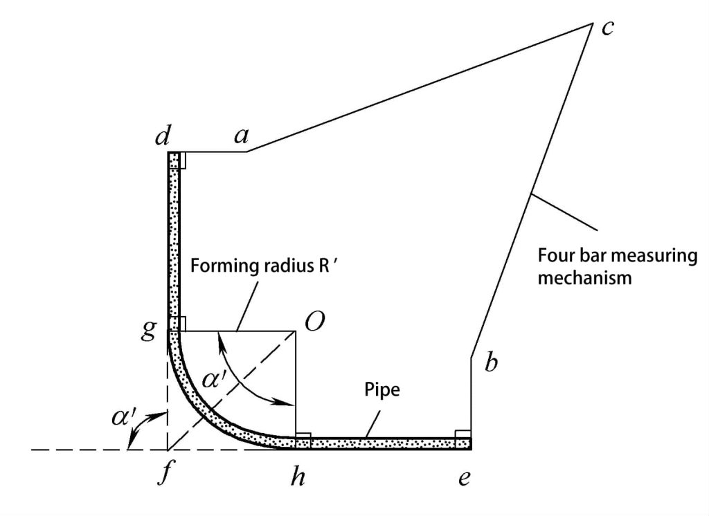
The measuring mechanism of the instrument is a four-bar planar mechanism as shown in Figure 4-27, with an angle sensor installed at nodes a, b, and c, which can measure the angle between two adjacent rods. The measuring heads at d and e are planar, so during measurement, the rods ad and be can be perpendicular to the straight pipe section of the dghe pipe.

The lengths of each rod in the four-bar planar mechanism are known, so the relevant geometric parameters of the dghe pipe can be measured and calculated. The method is as follows:
1) Based on the known conditions of the mechanism and the angle measured by the angle sensor, the forming angle α’ of the pipe can be calculated.
2) Based on the known conditions of the mechanism and the angle measured by the angle sensor, the distances df and fe of the intersection points of the straight pipe axis can be calculated.
3) When the distance dg of the starting bending point of the pipe fitting is known, the actual forming radius R’ can be further calculated.
R’=O g = (df-dg) / tan(α’/2)
4) The length L’ of the pipe axis can be further calculated.
L’=df+fe-2R’tan(α’/2) +πR’α’/180
Based on the above principles and formulas, it is only necessary to bend two test pieces of the same length L and starting bending points at distances d and g respectively on the pipe bender at predetermined angles (H 1 =30°, H=90°), then remove them and measure with a smart pipe bending measuring instrument, which can automatically complete the actual measurement and print out the rebound variation pattern, elongation variation pattern, and the formed radius after rebound of different metal materials and pipe models.
If the pipe shape of the workpiece is given, the instrument can also provide the blanking data for bending without allowance, and can provide the processing program for the CNC pipe bender, including starting point correction and rebound compensation (the instrument also has the function of measuring pipe shape). The data provided by the instrument not only greatly improves the forming accuracy of the CNC pipe bender but also promotes technological progress, achieving the purpose of reducing labor intensity, saving steel, and improving production efficiency.
5. Bending Radius
The degree of bending deformation of the pipe material depends on the values of the relative bending radius R/D and the relative thickness t/D (R is the curvature radius of the pipe material’s cross-sectional center layer, D is the outer diameter of the pipe material, t is the wall thickness of the pipe material). The smaller the values of R/D and t/D, the greater the degree of bending deformation, the outer wall of the bending neutral layer will become excessively thin, even leading to rupture; the innermost wall will thicken, even becoming unstable and wrinkling.
At the same time, as the degree of deformation increases, the distortion of the cross-section (flattening) will also become more severe. Therefore, to ensure the forming quality of the pipe material, it is necessary to control the degree of deformation within an allowable range. The allowable degree of deformation for bending the pipe material is called the bending forming limit. The bending forming limit of the pipe material depends not only on the mechanical properties of the material and the bending method but also on the requirements for the use of the pipe fittings.
For general-purpose bent parts, the condition for defining the forming limit is that the maximum elongation strain ε max produced at the position farthest from the neutral layer on the outer section of the bending deformation area should not exceed the limit value allowed by the material’s plasticity.
Under the condition that the outer surface layer outside the deformation area of the pipe fitting bending does not crack, the limit bending radius r min that can be bent into the inner side of the part is used as the forming limit of pipe fitting bending. r min is related to the material mechanical properties, pipe fitting structure size, bending processing method, and other factors.
The minimum bending radius for different bending processing methods is shown in Table 4-6.
Table 4-6 Minimum bending radius for pipe bending (unit: mm)
| Bending Methods | Minimum Bending Radius (rmin) |
| Press Bending | (3~5)D |
| Wrap Bending | (2~2.5)D |
| Roll Bending | 6D |
| Push Bending | (2.5~3)D |
Note: D is the outer diameter of the pipe.
The minimum bending radius for steel pipes and aluminum pipes is shown in Table 4-7.
Table 4-7 Minimum bending radius for steel pipes and aluminum pipes (unit: mm)
| Pipe outer diameter | 4 | 6 | 8 | 10 | 12 | 14 | 16 | 18 | 20 | 22 |
| Minimum bending radius rmin | 8 | 12 | 16 | 20 | 28 | 32 | 40 | 45 | 50 | 56 |
| Pipe outer diameter | 24 | 28 | 30 | 32 | 35 | 38 | 40 | 44 | 48 | 50 |
| Minimum bending radius rmin | 68 | 84 | 90 | 96 | 105 | 114 | 120 | 132 | 144 | 150 |

