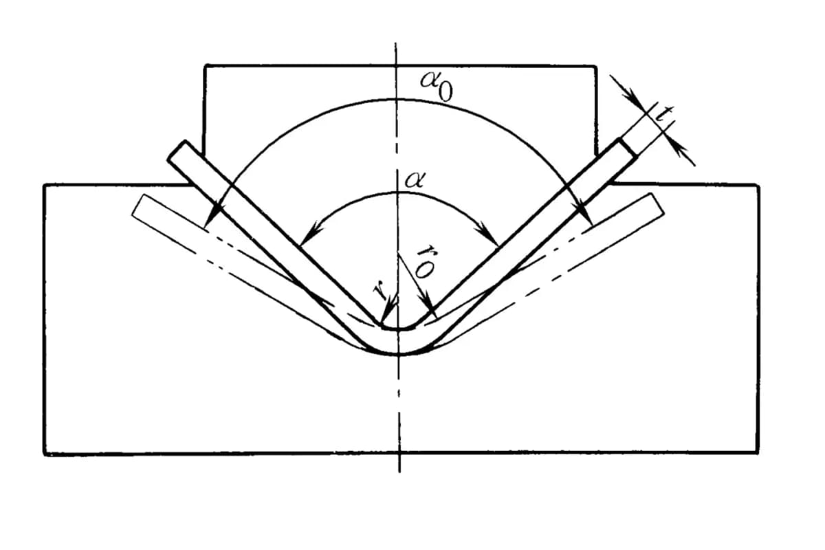
As mentioned before, plastic deformation and elastic deformation coexist when bending, and after the external load is removed, the workpiece rebounds, making its dimensions inconsistent with the mold dimensions (see Figure 1).
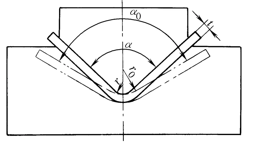
Springback is generally represented by the change in angle: when bending with a large radius of curvature, in addition to calculating the springback angle, it is also necessary to calculate the change in the bending radius.
I. Main factors affecting springback
1. Mechanical properties of the material
The higher the yield strength σ s , the smaller the elastic modulus E, and the more intense the work hardening (higher k and n values), the greater the springback.
2. Relative bending radius r/t
When r/t is small, the overall tangential deformation on the outer surface of the bending blank is large. Although the numerical value of elastic deformation also increases, the proportion of elastic deformation in the total deformation decreases. Therefore, the ratio of the springback angle to the bending angle △α/α and the ratio of curvature springback to the radius of curvature △ρ/ρ both decrease as the bending radius decreases.
3. Bending angle α
The larger the bending angle α, the longer the deformation zone, and thus the larger the springback angle, but it does not affect the rebound of the radius of curvature.
4. Bending methods and die structures
Different bending methods and die structures have a significant impact on the bending process, stress conditions, and the influence on the deformed and non-deformed areas of the blank, thus the springback values also vary.
5. Bending force
In actual production, bending methods with a certain correction component are often used, allowing the press to exert a force greater than what is needed for bending deformation. At this time, the stress state and the nature of the strain in the bending deformation area have certain differences from pure bending, and the greater the applied force, the more significant this difference. When the correction force is very large, it may completely change the nature of the stress state in the blank deformation area and cause the non-deformation area to also become a deformation area.
6. Friction
The friction between the surface of the bending blank and the surface of the die can change the stress state of various parts of the bending blank, especially when bending into multiple parts with different curvatures, the impact of friction is more significant.
It is generally believed that friction can increase the tensile stress in the bending deformation area in most cases, making the shape of the part closer to that of the die. However, during stretch bending, the impact of friction is often adverse.
7. Thickness deviation
If there is a large thickness deviation in the blank, for a given die, the actual working gap varies, thus the springback value also fluctuates.
II. Approximate calculation
In free bending, the simplified formula for estimating the springback angle is shown in Table 1.
Table 1 Approximate formula for calculating springback angle in free bending
| Bending method | Springback angle β (single side) calculation formula |
| Bending of V-shaped parts | tanβ = 0. 375l/Kt·σs/E |
| Bending of U-shaped parts | tanβ = 0.375l1/Kt·σs/E |
Note:
K———coefficient, determined by the position of the neutral layer;
l———distance of the fulcrum, i.e., the width of the die opening;
l 1 ———bending lever arm, l 1 = rpunch + rdie + 1.25t.
In bending with a pressure pad, the value of springback not only depends on the values of r/t, l/t, and α, but also on the adjustment of the press and the degree of cold work hardening of the metal.
III. Empirical Data
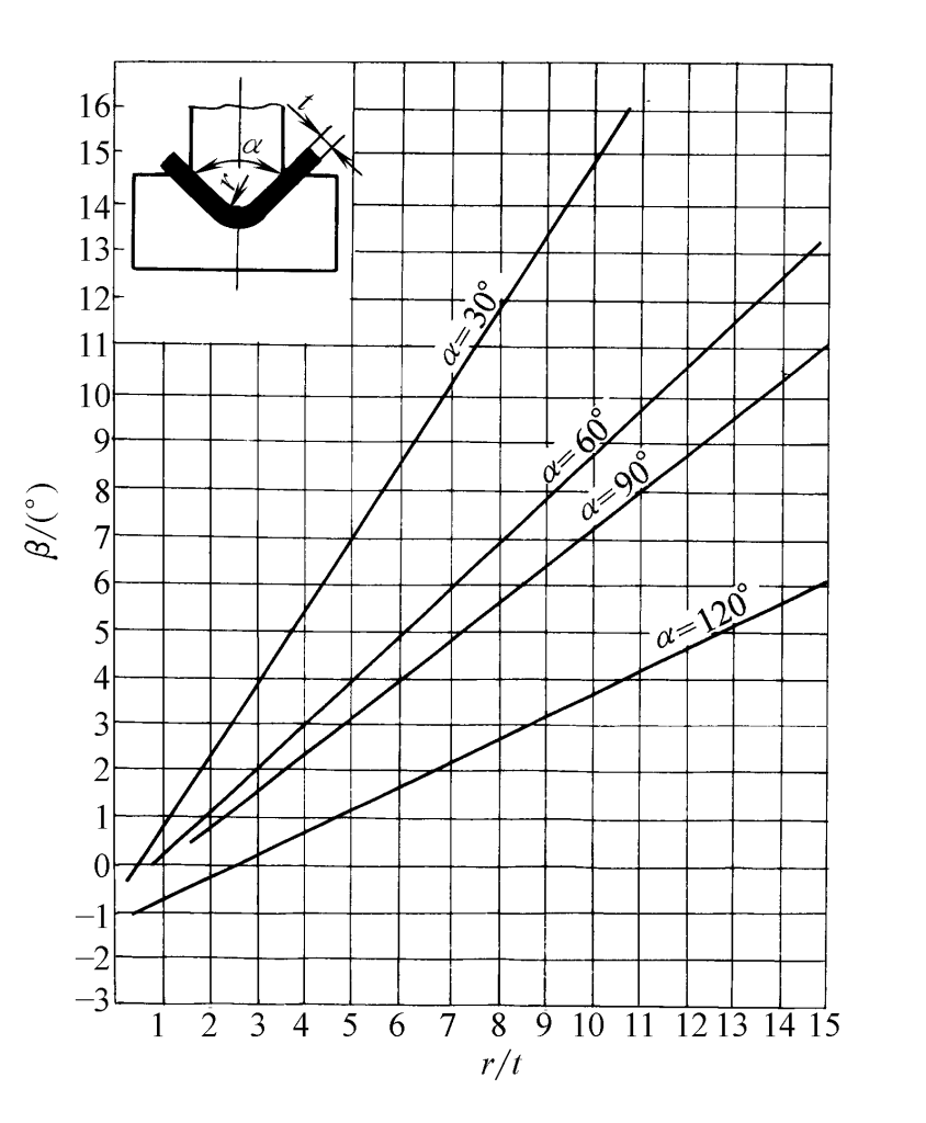
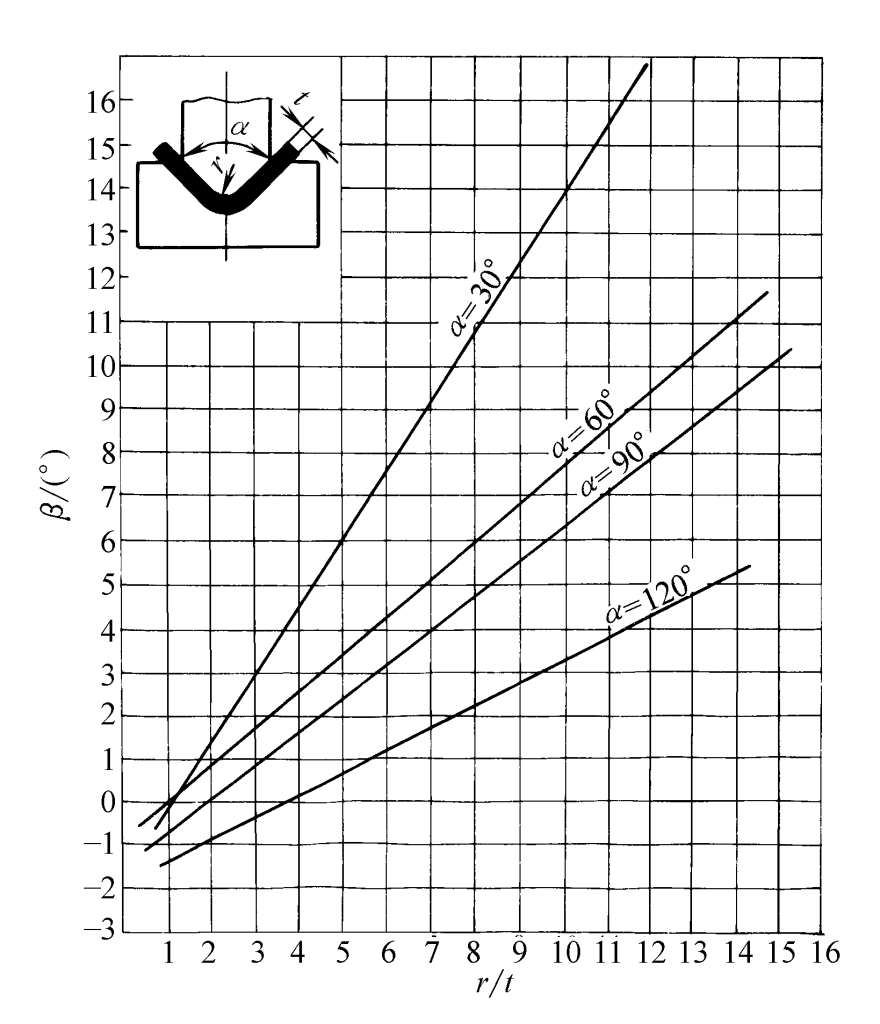
For carbon steel plates undergoing V-bending, the relationship between the springback angle β and r/t is shown in Figures 2 to 5.
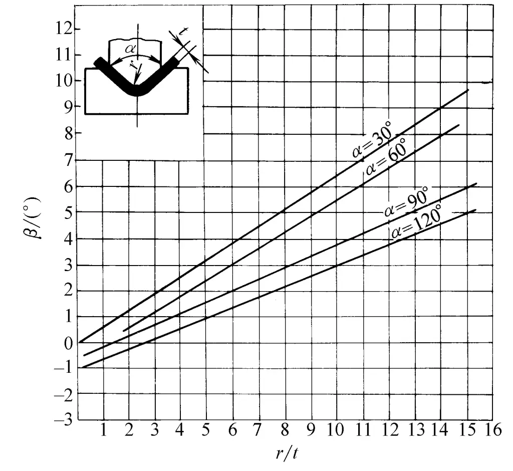
- When α = 30°, β = 0. 75r/ t -0. 39
- When α = 60°, β = 0. 58r/ t -0. 80
- When α = 90°, β = 0. 43r/ t -0. 61
- When α = 120°, β = 0. 36r/ t -1. 26
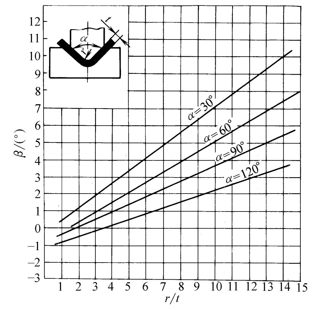
- When α = 30°, β = 0.69r/t -0.23
- When α = 60°, β = 0.64r/t -0.65
- When α = 90°, β = 0.434r/t -0.36
- When α = 120°, β = 0.37r/t -0.58
- When α = 30°, β = 1.59r/t -1.03
- When α = 60°, β = 0.95r/t -0.94
- When α = 90°, β = 0.78r/t -0.79
- When α = 120°, β = 0.46r/t -1.36
- When α = 30°, β = 1.51r/t -1.48
- When α = 60°, β = 0.84r/t -0.76
- When α = 90°, β = 0.79r/t -1.62
- When α = 120°, β = 0.51r/t -1.71
IV. Main Measures to Reduce Springback
1. Under conditions close to pure bending, necessary corrections can be made to the shape of the working part of the bending mold based on the calculation of springback values or empirical data.
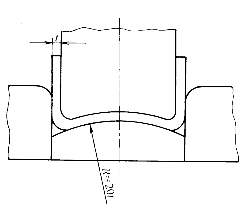
2. By utilizing the pattern that different parts of the bending blank have different springback directions, various influencing factors (radius of the mold’s round corner, clearance, opening width, correction force, pressing force, etc.) can be appropriately adjusted to cancel out the springback in opposite directions. As shown in Figure 6, the springback generated at the bottom of the part is used to compensate for the springback at the two rounded corners.
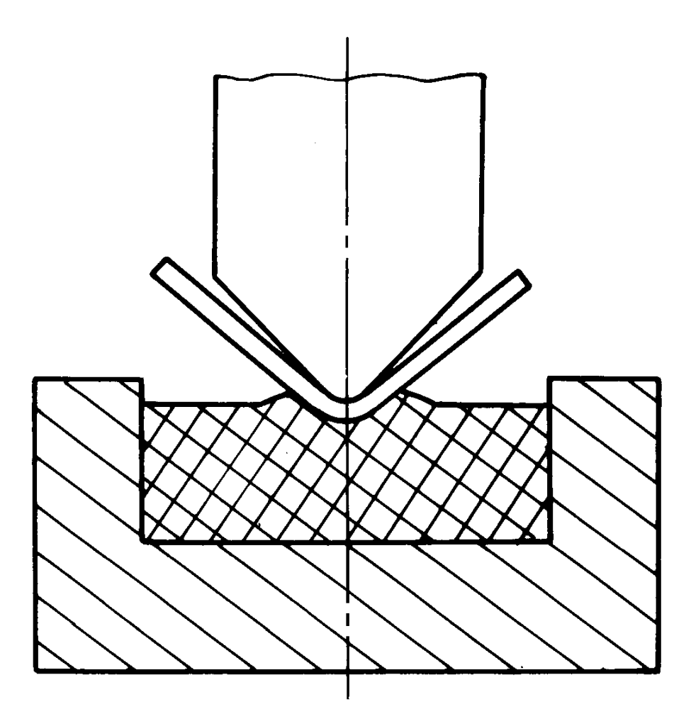
3. Use a soft concave mold made of polyurethane rubber instead of a rigid metal concave mold for bending, as shown in Figure 7.
4. Make the bending punch or pressing plate into a shape with local protrusions, or reduce the mold gap at the rounded corners, so that the punch force is concentrated in the bending deformation area that causes springback, changing its stress state, as shown in Figure 8.
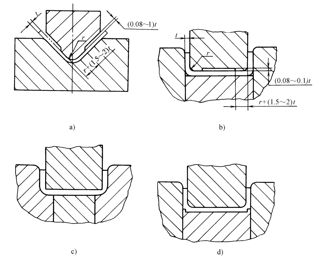
5. Use a concave mold structure with a swinging block, as shown in Figure 9.
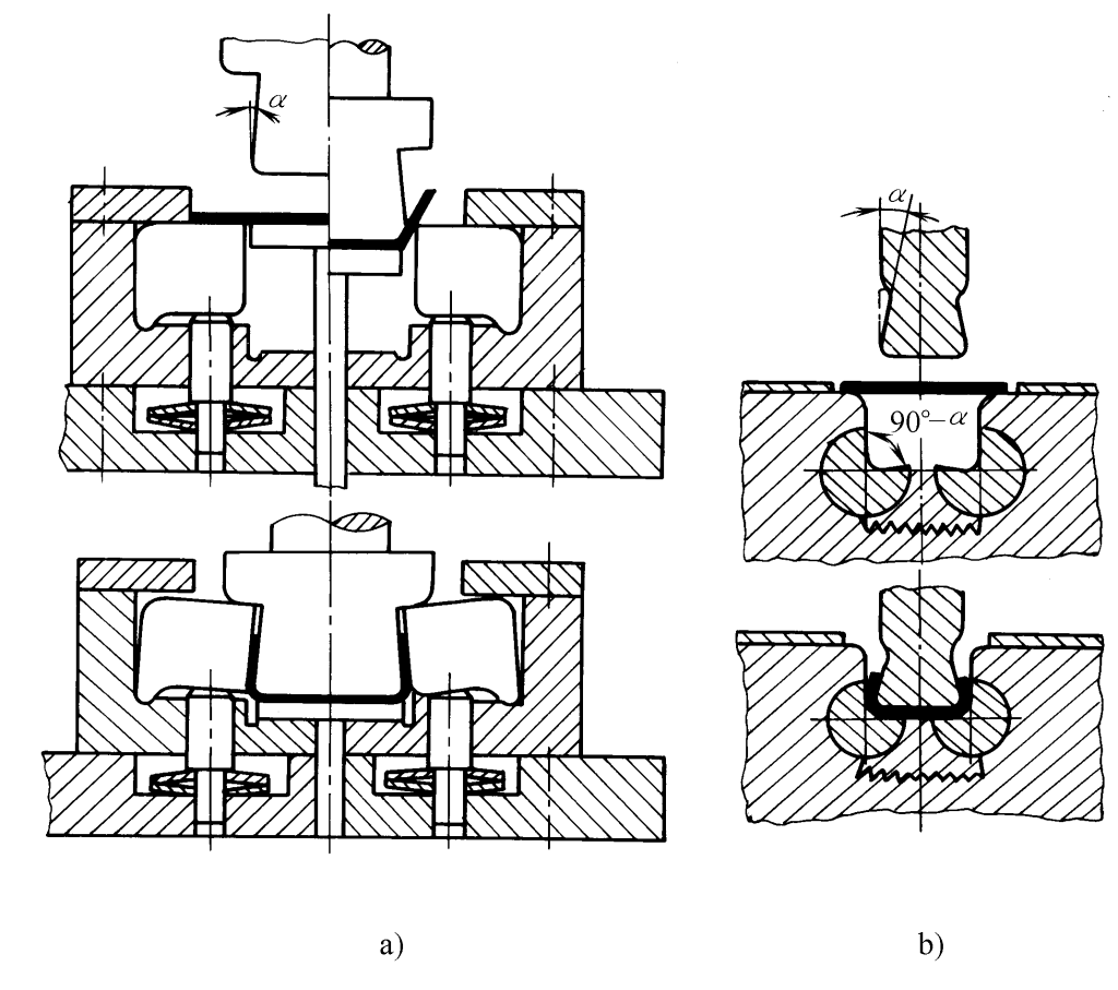
6. Use the longitudinal pressing method, after the bending process is completed, use the mold’s protruding shoulder to longitudinally press on the bending blank, making all the stresses on the cross-section of the blank in the bending deformation area become compressive stresses, as shown in Figure 10.
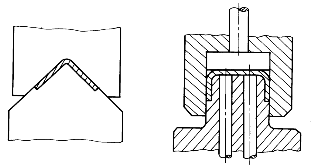
7. Use the draw bending method, mainly for parts with both large length and radius of curvature.
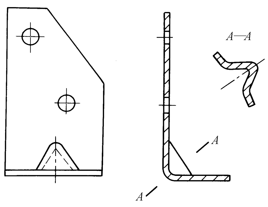
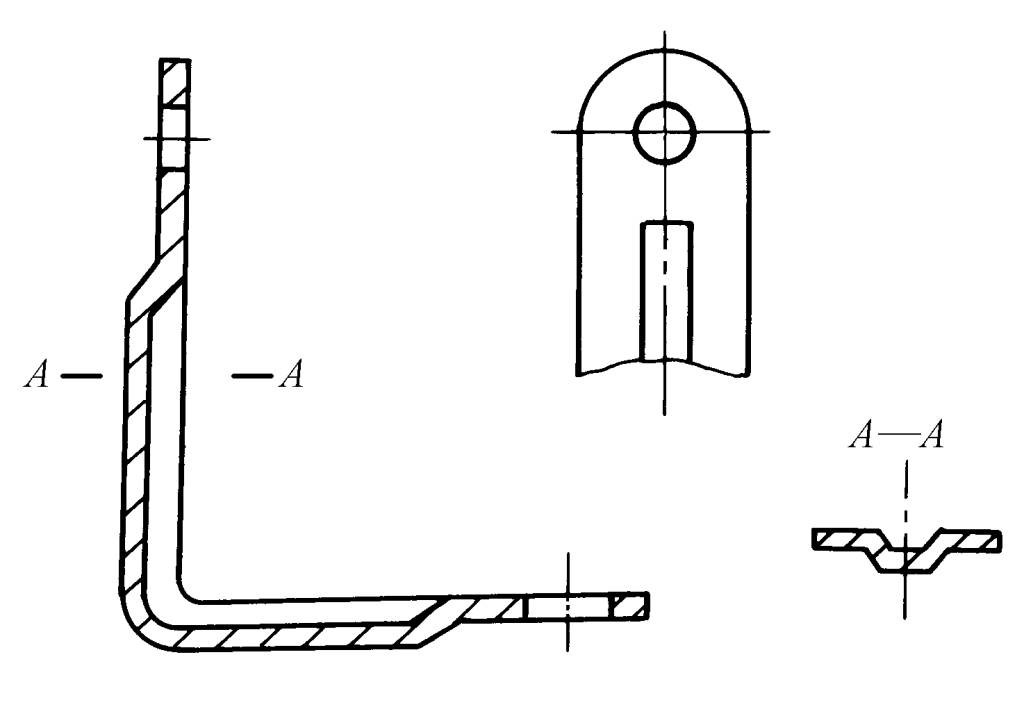
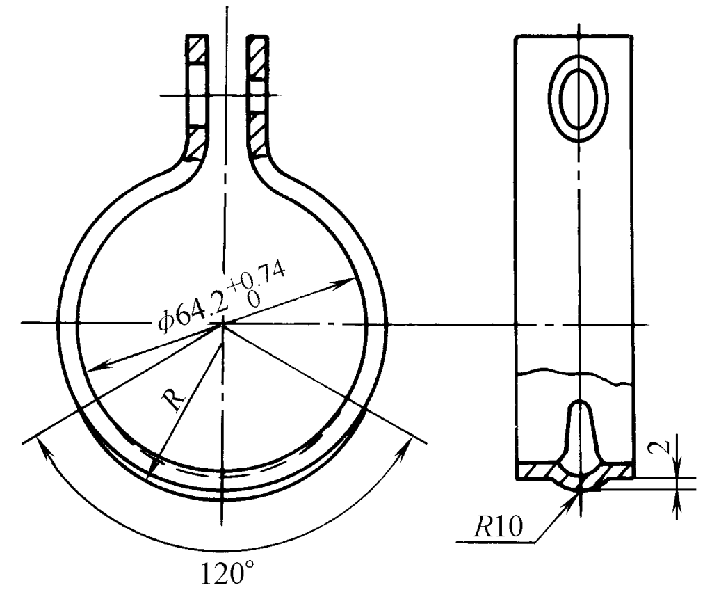
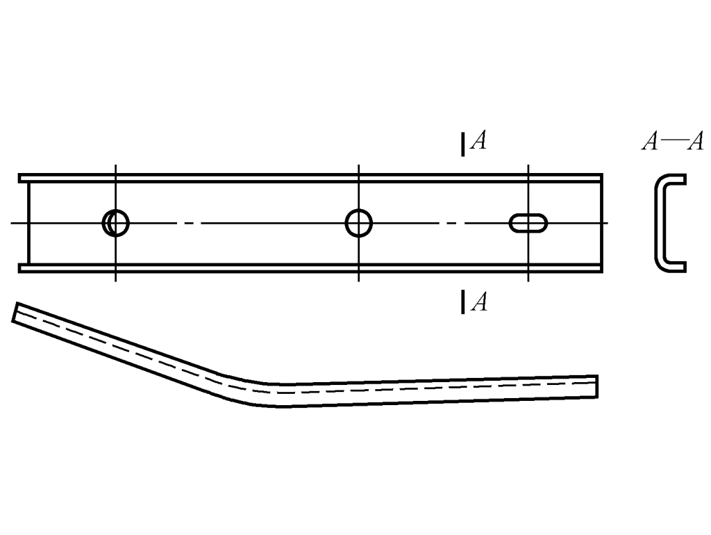
8. Use methods to improve the structural rigidity of the parts, as shown in Figures 11 to 14.
