Hydraulic Press Brake vs. Folding Machine: A Comprehensive Guide
I. Overview 1. Process Introduction and Drive Mode The press brake is a processing machinery that bends metal sheets into [...]
Sheet metal bending involves both plastic and elastic deformation. Upon the removal of the bending force, the elastic deformation immediately disappears, leaving only the plastic deformation.
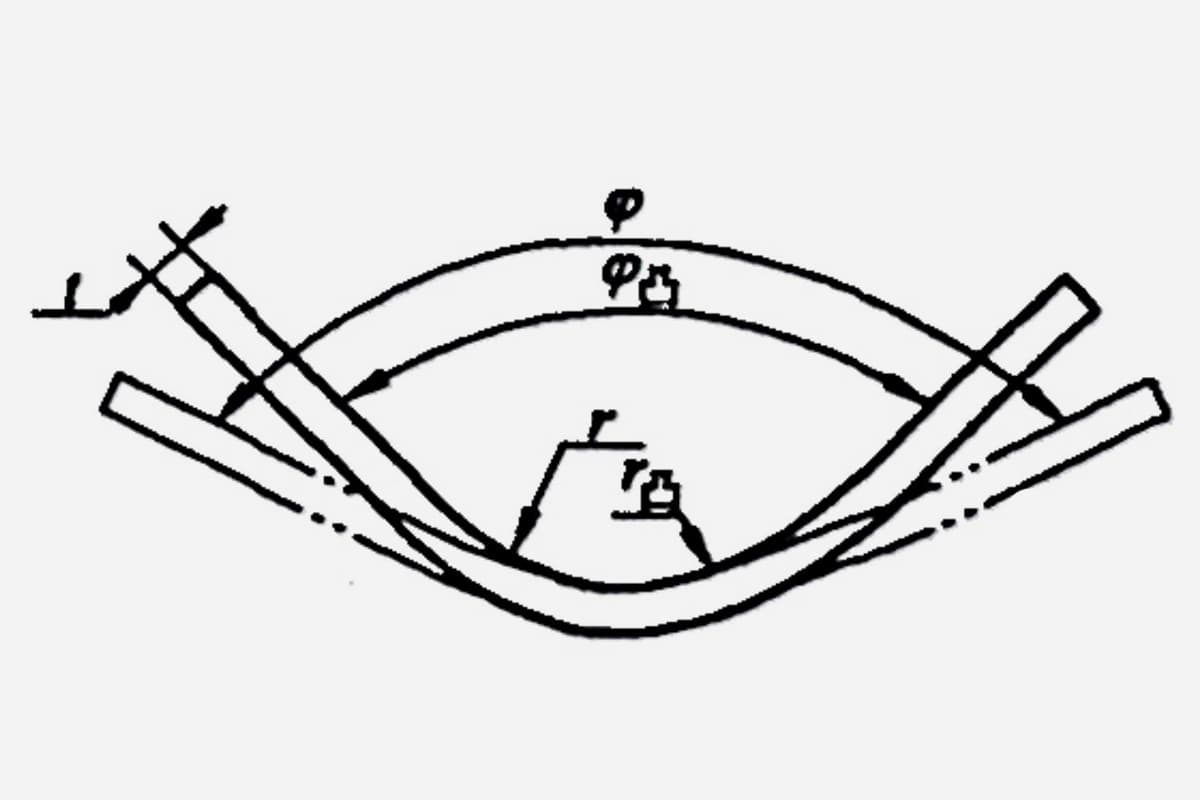
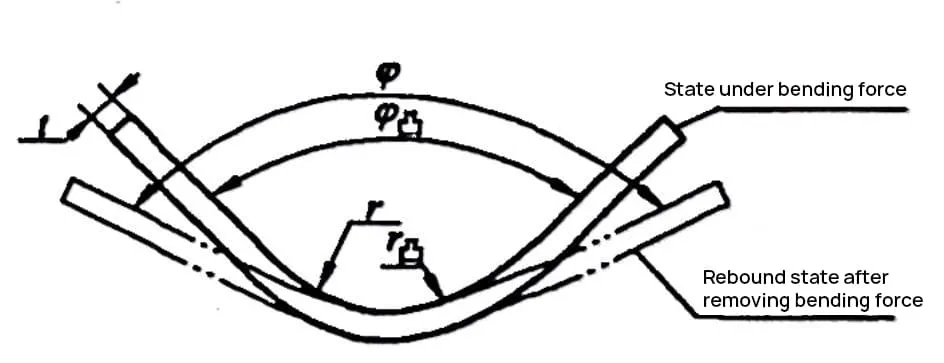
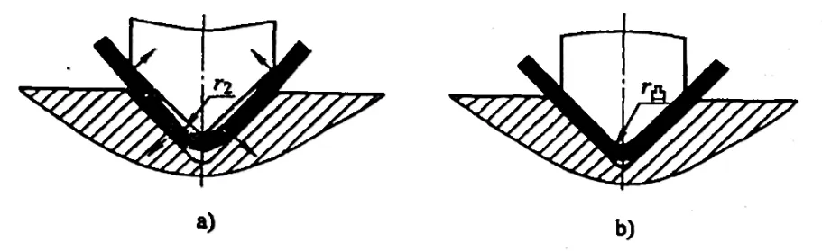
This results in a discrepancy between the shape and size of the bent part and the bending die, a phenomenon we refer to as springback. The schematic diagram of springback is shown in Figure 1-1.
In bending operations, springback is a common occurrence and a significant factor affecting the accuracy of bent parts.
The difference in shape and size between the bent part and the bending die is known as the springback value. The springback angle of the bend is denoted by ∆φ=φ-φ凸, and the springback value of the bend radius is denoted by ∆r=r-r凸. When the bend radius is large, in addition to determining the springback angle ∆φ, the springback value ∆r of the bend radius must also be calculated.
The factors influencing the springback of bent parts are numerous and highly complex. Herein, we will mainly discuss a few of the most significant ones.
The size of the springback angle is directly proportional to the yield strength αa of the material and inversely proportional to the elastic modulus (E). That is, the higher the yield strength and the smaller the elastic modulus of the material, the smaller the springback; conversely, the larger the springback.
For bent parts with high precision requirements, to minimize springback, low carbon steel should be chosen over materials such as high carbon steel or stainless steel.
The larger the relative bending radius (r/t), the lesser the degree of bending deformation, resulting in a smaller region of plastic deformation within the blank and a lesser degree of overall deformation. Hence, the proportion of plastic deformation in total deformation decreases, leading to larger springback.
Conversely, a smaller relative bending radius signifies a higher degree of bending deformation, resulting in smaller springback. This is an important concept. When the material properties allow, the fillet of sheet metal bent parts should choose the smallest possible bending radius to improve machining precision.
It is particularly noteworthy that parts with large bending radii present certain challenges in controlling machining precision and quality.
When the bending radius and material thickness are fixed, the larger the bending central angle (α=180°-φ), the larger the area involved in the bending deformation, and the accumulated amount of elastic deformation also increases, leading to larger total springback.
Conversely, a smaller bending central angle signifies a smaller deforming area, resulting in a smaller accumulated amount of elastic deformation and therefore smaller total springback.
Given a certain bending radius, central angle, and material thickness, a larger bending force F results in less springback, while a smaller bending force leads to more springback.
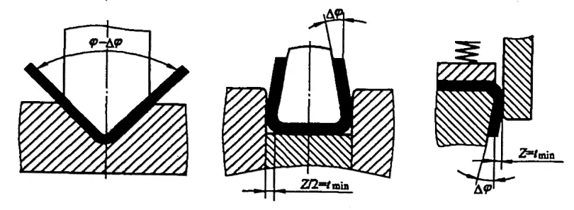
In free bending (as shown in Figure 1-2), the workpiece under the influence of the die groove rebounds in the same direction in both the straight-edge part and the R part of the round corner, resulting in maximum springback and no negative springback. The direction of springback during the correction bending of the workpiece is shown in Figure 1-3.

In terms of the springback of the straight edge of the workpiece, under the influence of the V-shaped surface of the die, the blank contacts the punch at three points, as shown in Figure 1-3a. As the punch continues to descend, the deformation direction of the straight edge is opposite to that of free bending (see Figure 1-2).
Upon completion of bending, under the effect of bending force, the deformed surface produced in the blank during the bending process is re-flattened and completely adheres to the punch and die, as shown in Figure1-3b.
After removing the bending force, the springback of the straight edge of the workpiece is towards the inside of the V-shape (negative springback), while the R part of the round corner rebounds towards the outside of the V-shape (positive springback), with the two springback directions being opposite.
For the springback of the R part of the round corner of the workpiece, the compressive action of the punch and die reduces the tensile stress of the outer fibers of the R part of the round corner, creating compressive stress near the neutral layer of the R part of the round corner.
As the correction force increases, the compressive stress zone gradually extends to the outer layer, indicating that all or most of the cross-section of the blank is under compressive stress. Therefore, the springback direction of the inner and outer areas of the R part of the round corner is consistent, hence, the springback of the R part in correction bending is much less than in free bending.
From the above analysis, it is evident that the springback of the bending R part and the straight part cancel each other out. The overall springback could be positive, zero, or negative, depending on the relative bending radius (r/t), the width of the lower die slot Bv, the central angle a of bending, and the magnitude of bending force F.
When the relative bending radius (r/t) is small, the width of the lower die slot Bv is large, the central angle a is small, and the bending force F is large, negative springback will occur; otherwise, positive springback will ensue. In actual production, there are many factors influencing springback, making it difficult to control springback to zero.
Therefore, parameters such as the relative curvature radius (r/t), the width of the lower die slot Bv, and bending force F should be appropriately selected to control springback and ensure the precision and quality of the bent part.
The shape, size, and die structure of the bent part also affect its springback. When the straight edge of the bent part is short, the springback is larger. The springback of a V-shaped bent part is larger than that of a U-shaped bent part. The more complex the bent part, the more rounded corners in the R part formed in a single bend, the greater the mutual restraint during bending, the bigger the drawing forming component, and the smaller the springback value.
When bending a U-shaped part, the gap between the convex and concave dies has a significant effect on the springback of the U-shaped part. The larger the gap, the greater the springback; conversely, the smaller the gap, the smaller the springback due to the thinning effect (extrusion) of the die on the plate. When the depth of the concave die is too small, the springback is also large.
In addition, when bending a U-shaped part without using a top tool, and without correction, the straightening of the bottom bow shape and the springback of the arc will result in outward (positive) springback.
If no top tool is used and correction is performed later, as the bottom bow shape is flattened last, a springback in the same direction as the bottom bow shape will occur when the convex die rises, resulting in inward (negative) springback.
If a top tool is used, the material at the bottom of the convex die will not flex from the beginning, and the workpiece can only produce outward springback. Therefore, by adjusting the pressure of the top tool, the springback of the bottom and the arc part could cancel each other out, possibly yielding a workpiece with minimum springback.
In production practice, to manufacture a part with a certain shape and dimensional accuracy, the issue of determining the size of the springback value often arises. There are many factors affecting springback, the theoretical calculation methods are extremely complex and highly inaccurate, thus lacking practical value. Usually, the springback value is initially determined based on empirical data and simple calculations, and then corrected after multiple bending tests.
When the relative bending radius (r/t)<5, the change in the radius of curvature is not significant and can be ignored, considering only the springback of the angle. The springback for a single 90° free angle is shown in Table 1-1.
Table 1-1 Springback angle for single 90° free bending
| Materials | r/t | Material Thickness t/mm | ||
| <0.8 | 0.8~2 | >2 | ||
| Low-Carbon Steel | <1 | 4° | 2° | 0° |
| Brass (δb=350MPa) | 1-5 | 5° | 3° | 1° |
| Aluminum, Zinc | >5 | 6° | 4° | 2° |
| Medium-Carbon Steel (δb=400-500MPa) | <1 | 5° | 2° | 0° |
| Hard Brass (δb=350-400MPa) | 1-5 | 6° | 3° | 1° |
| Hard Bronze (δb=350-400MPa) | >5 | 8° | 5° | 3° |
| High-Carbon Steel (δb>550MPa) | <1 | 7° | 4° | 2° |
| 1~5 | 9° | 5° | 3° | |
| >5 | 12° | 7° | 6° | |
| Hard Aluminum (2A12) | <2 | 2° | 3° | 4°30′ |
| 2-5 | 4° | 6° | 8°30′ | |
| >5 | 6°30′ | 10° | 14° | |
From the analysis above, it can be inferred that the larger the relative bend radius (r/t), the smaller the degree of bending deformation, and consequently, the greater the rebound. Not only does the part exhibit angle rebound, but there is also significant rebound in the bending radius. In such cases, calculations can be performed using the pure plastic bending formula and then corrected in actual production.
As illustrated in figure 1-1, the calculation formulas for the work part radius of the convex die and the central angle of the rounded part, according to pure calculations, are as follows:

In the formula,
In the bending process of sheet metal parts, springback is always present due to the simultaneous occurrence of plastic and elastic deformation, and it cannot be eliminated.
Therefore, in practical production, measures must be taken to compensate for the errors caused by the springback of bent parts to ensure product quality.
Common methods to reduce springback generally include compensation techniques, correction methods, changing stress conditions, and improving the design of bent part structures.
There are many factors affecting the springback of bent parts, and different measures should be taken for different influencing factors, or a combination of several methods can be used to reduce springback.
Without affecting the functional use of the bent part, improving some structural designs of the bent part can reduce the springback angle. For example, suppressing reinforcement ribs in the bending area (Fig. 7-4a) or using formed edges (Fig. 7-4b) can increase the stiffness and plastic deformation of the bent part, thereby reducing springback.
Under the conditions of meeting usage requirements, the use of materials with high elastic modulus, low yield strength, low hardness, and good plasticity can reduce springback and facilitate springback control.
1) Replace free bending with corrective bending.

2) For cold-work hardened sheet metal, annealing can be performed before bending to lower the yield strength (a), thus minimizing rebound. Hardening can be done post-bending, but caution must be exercised: if annealing affects the material’s usability, this process should not be adopted.
3) The punch radius should be as close as possible to the minimum bending radius, and the die depth should generally be >10t.
4) For large (long) bends with a relative bend radius (r/t>100), most of the blank is in elastic deformation, resulting in significant rebound. Some may even be impossible to form using conventional bending methods. In such cases, draw bending can be used.
Draw bending is a stamping process where the sheet metal blank is bent to a certain curvature, shape, and size, as shown in Figure 1-5a. It is suitable for workpieces with a large relative bend radius and is widely used in the manufacture of high-pressure vessels, steel plates and skeletons of ship hulls, various vessels, and edging for cabinets.
Draw bending involves applying a certain tensile stress to the blank before bending. The combined force of this tensile stress and the compressive stress of the inner layer of the blank bending should be slightly greater than the material’s yield strength (a), and the bend deformation is completed under this tensile state. The internal stress distribution in the blank during draw bending is shown in Figure 1-5b.
There are three methods of draw bending: bending after applying tensile stress, applying tensile stress while bending, and stretching after bending. Among these three methods, stretching after bending results in the smallest rebound value.
Draw bending not only increases the deformation of the bent part, but also causes almost uniform plastic deformation across the entire cross-section of the bent part. Thus, it can greatly reduce the rebound of the bent part.
5) For precision-required bent parts, a reshaping process can be added after bending.
Based on the estimated or experimental rebound value, we can compensate (or deduct) within the shape and size of the mold’s working part, enabling the bent part to obtain the shape and size required by the product drawing.
1) Soft materials such as 0215, 0235, 08, 10, 20, H2 soft brass, etc., have a bending rebound angle φ <5°. When the material thickness deviation is small, a slope (rebound compensation angle) can be designed on the punch or die. The clearance between the punch and the die is equal to the minimum material thickness, or even negative clearance can be used to overcome the rebound, as shown in Figure 1-6.
2) For soft materials such as Q215, Q235, 08, 10, 20, and H62 soft brass, when the material thickness exceeds 0.8mm, and the bending radius is large, the working part of the punch can be designed to have a localized protrusion. This concentrates the working pressure of the punch at the corner of the bend.
By increasing the stress at the bend, we enhance the plastic deformation component in the deformation zone, improve the stress distribution, thus reducing elastic deformation and minimizing springback, as shown in Figure 1-7.

3) For hard materials such as Q275, 45, 50, H62 hard brass, etc., when the bending radius r>t, the springback compensation angle can be designed on the die or punch according to the pre-estimated or experimentally obtained springback value, to eliminate the springback.
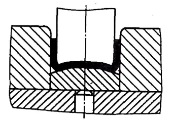
Alternatively, the top of the die can be designed as an arcuate surface (for U-shaped bending), as shown in Figure 1-8, producing a local reverse bend at the bottom. That is, when the part is removed from the mold, the rebound of the reverse curve causes negative springback on both sides, offsetting the positive springback of the side walls.
4) For Z-shaped bending, the two bending angles of the Z-shaped bend may have different springback values, potentially leading to non-parallel top and bottom surfaces on the Z-shaped part. To avoid this phenomenon, the punch and die should be tilted outward by an angle of Δφ. For cold-rolled sheets with a thickness of less than 1mm, the tilt angle generally takes 2°~3°, as shown in Figure 1-9.

5) For softer materials, a rubber die can be used instead of a rigid die, as shown in Figure 1-10. Since rubber can transmit pressure in all directions like a liquid within a rigid container, the bending process undergoes beneficial changes compared to using a rigid mold.

The sheet is fully supported on the rubber, and the middle support is stronger than the sides, so when the two straight walls of the sheet are bent around the round corner of the punch, they fully adhere to the punch surface, and the straight wall part is not prone to over-bending, reducing springback.
If high-hardness rubber elastomers are used, the effect is even better. In addition to high precision, the use of rubber dies leaves no scratches on the surface of the bent parts, and the versatility of rubber and rubber elastomer dies is very good.
Reducing the die clearance contributes to decreased springback. When the clearance between the bending die faces is smaller than the material thickness, the springback can be significantly reduced, or even result in slight negative springback. Suitable single-side bending die clearance is between 0.02mm to 0.5mm less than the material thickness, typically set at 0.03mm.
Excessively small clearances can lead to material thinning, workpiece surface scratching, and a reduction in die life. When the sheet blank thickness is negatively deviated, an overly large gap formed between the punch and the die can also cause springback. The solution is to design adjustable clearance bending dies, as shown in Figure 1-11.