Cold Extrusion Core Principles and Types Explained
How do metal parts achieve complex shapes without heating? The answer lies in cold extrusion, a fascinating process that molds…
Why do cold extrusion dies fail so often? It’s a question many in manufacturing ask. In this article, we explore the primary causes of die damage, including excessive stress, improper material selection, and poor maintenance. We’ll provide actionable tips on preventing issues like deformation, fractures, and cracks, ensuring longer die life and smoother production processes. By understanding and mitigating these factors, you can enhance the reliability and efficiency of your cold extrusion operations. Read on to learn how to safeguard your tools and improve your workflow.
The punch die is the most crucial part of the cold extrusion die. It must be able to withstand high compressive loads and have enough toughness to prevent any minor bending from causing lateral pressure that would result in sudden fracture.
At the same time, the punch die must possess good wear resistance to prevent possible softening during heating, avoid potential scratches and biting, and prevent possible permanent deformation.
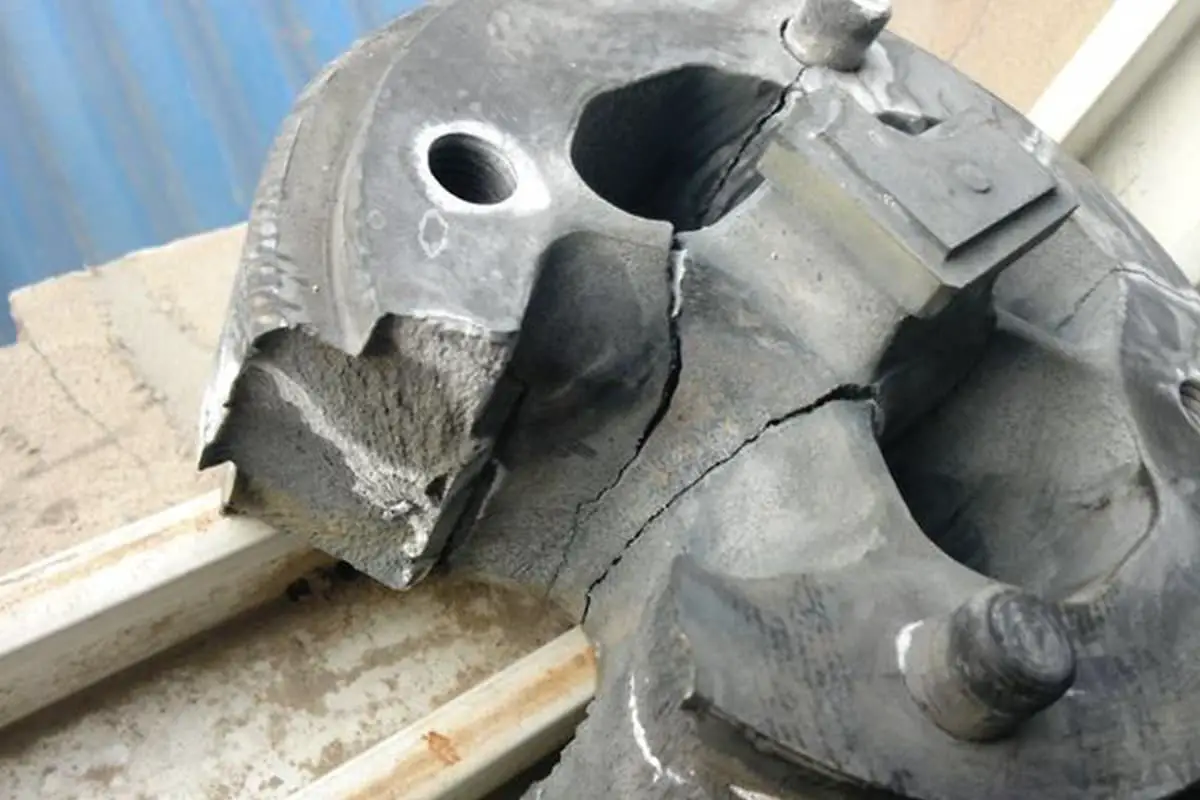
Damage to the cold extrusion punch die is primarily caused by excessive working stress, eccentric loads, and stress concentration leading to short-term fatigue. The main forms of damage are deformation, fracture, and breakage.
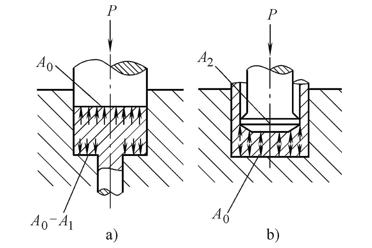
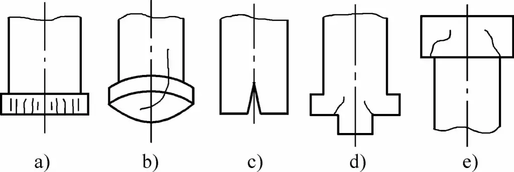
During the extrusion process, the punch die undergoes permanent deformations such as upsetting, deformation, and bending as shown in Figure 9-3, known as plastic deformation.
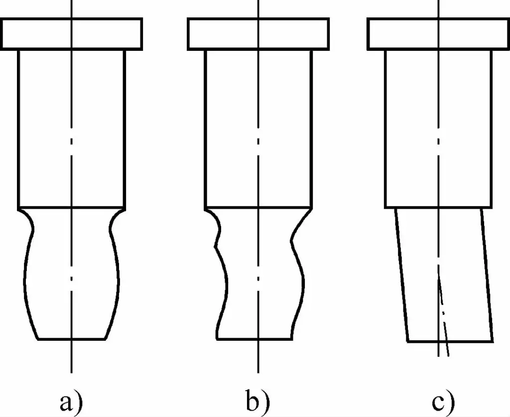
a) Swelling
b) Deformation
c) Bending
The main reasons causing plastic deformation of the punch die include:
To prevent the punch die from bending and deforming, it should be made of high-speed tool steel with good heat hardness and high compressive strength, with a hardness of over 61HRC after quenching and tempering. The precision of the blank should be improved, the two ends of the blank should be made parallel, and the hardness of the blank should be controlled to be below 110HBW.
In addition, the guiding accuracy and installation accuracy of the die should be improved to ensure the coaxiality of the punch and die during extrusion.
Fracture is the most damaging form of failure that directly affects the life of the punch die. The fracture of a punch die often starts from a very small nick or scratch, gradually expanding to form a circular crack, and in severe cases, cracking and sudden breakage occur. The main reasons for the formation of cracks are repeated alternating stress and periodic temperature changes.
During the cold extrusion process, a large amount of heat is generated in a short time, raising the temperature of the die, and each extrusion is a heat and cold cycle. Under this alternating heat and cold, the stress on the surface of the die alternates positively and negatively, leading to the formation of thermal fatigue cracks. Therefore, fatigue is one of the main reasons for the cracking of the punch die.
Additionally, when subjected to eccentric loads, cracks often occur at the junction of the fillet and the straight part, i.e., the part where the cross-section or shape changes, and even breakage can occur. Especially when the fillets at these transition parts are very small or not smoothly connected, cracking becomes more severe.
This is because these parts are stress concentration areas and the origin of crack formation. Therefore, designing these parts with appropriate fillets, carefully processing and polishing them to ensure smooth connection, and avoiding stress concentration, are effective ways to prevent crack formation.
Fractures of the punch die are divided into transverse cracks, longitudinal cracks, and radial cracks based on their destructive nature and the shape of the fracture site. There are two situations for transverse cracks, one is breakage as shown in Figure 9-4. Most breakages occur at the transition place, and sometimes at the working part of the extrusion piece and the fixed connection part of the punch die.
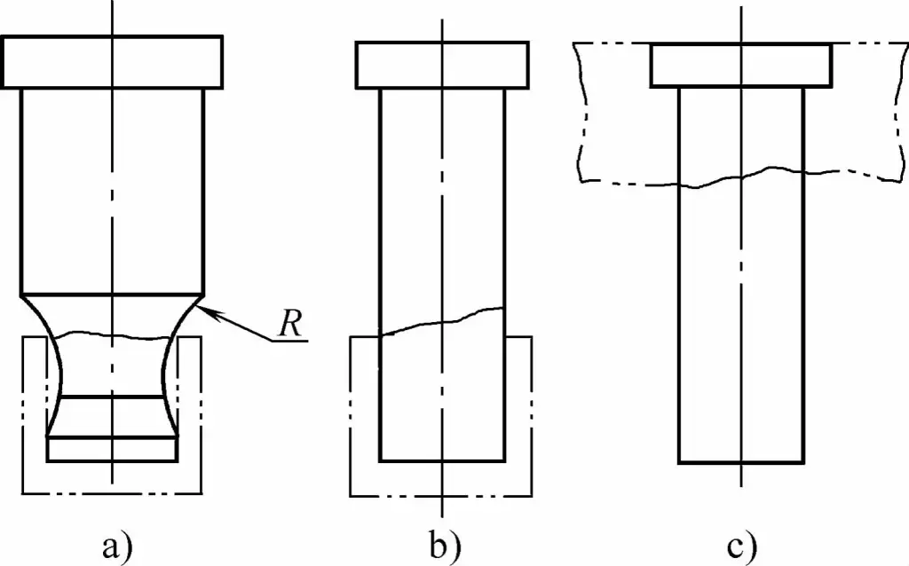
a) Crack at the Transition Area
b) Crack at the Edge of the Extruded Part
c) Crack at the Convex Mold Mounting Plate Area
Breakage is mainly caused by bending stress caused by eccentric loads, and is less affected by stress concentration. In the case of indirect extrusion of cup-shaped pieces, if the fillet R of the punch die overly restricts indirect extrusion, transverse cracks will occur there.
If the mouth part of the indirect extrusion piece is skewed, i.e., one side is high and one side is low, the bending moment caused by lateral force during withdrawal often causes the punch die to break, as shown in Figure 9-5. The other type of breakage, tensile breakage, mostly occurs at the part where the cross-section changes when lubrication conditions deteriorate.
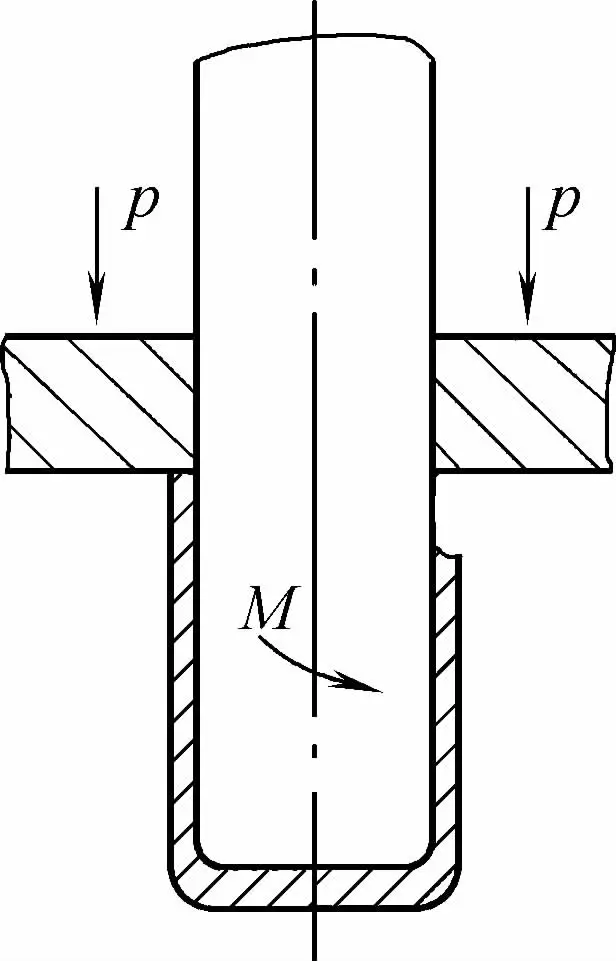
The main feature of tensile breakage is its flat fracture surface. Improving lubrication conditions and reducing friction are effective measures to prevent tensile breakage of the punch die.
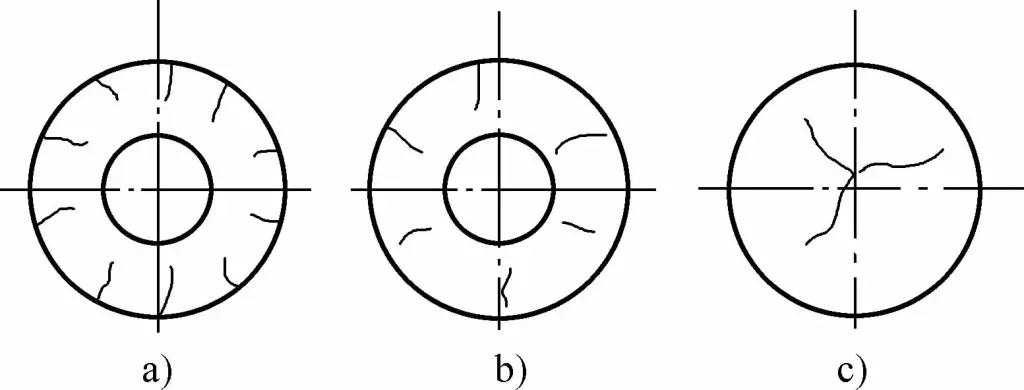
Common forms of longitudinal cracks are shown in Figure 9-6. The longitudinal crack shown in Figure 9-6a occurs on the circumference of the working ring belt. This is a fatigue nature crack caused by periodic, heat and cold alternating stress, and is also related to poor lubrication of the blank and insufficient hardness of the punch die.
a) Fatigue Crack
b) Longitudinal Split
c) Central Split
d), e) Corner Crack
To reduce the occurrence of these tiny longitudinal cracks, firstly, high-speed steel material with excellent toughness should be chosen, and nitrocarburizing treatment should be adopted to enhance the surface’s wear resistance and fatigue resistance.
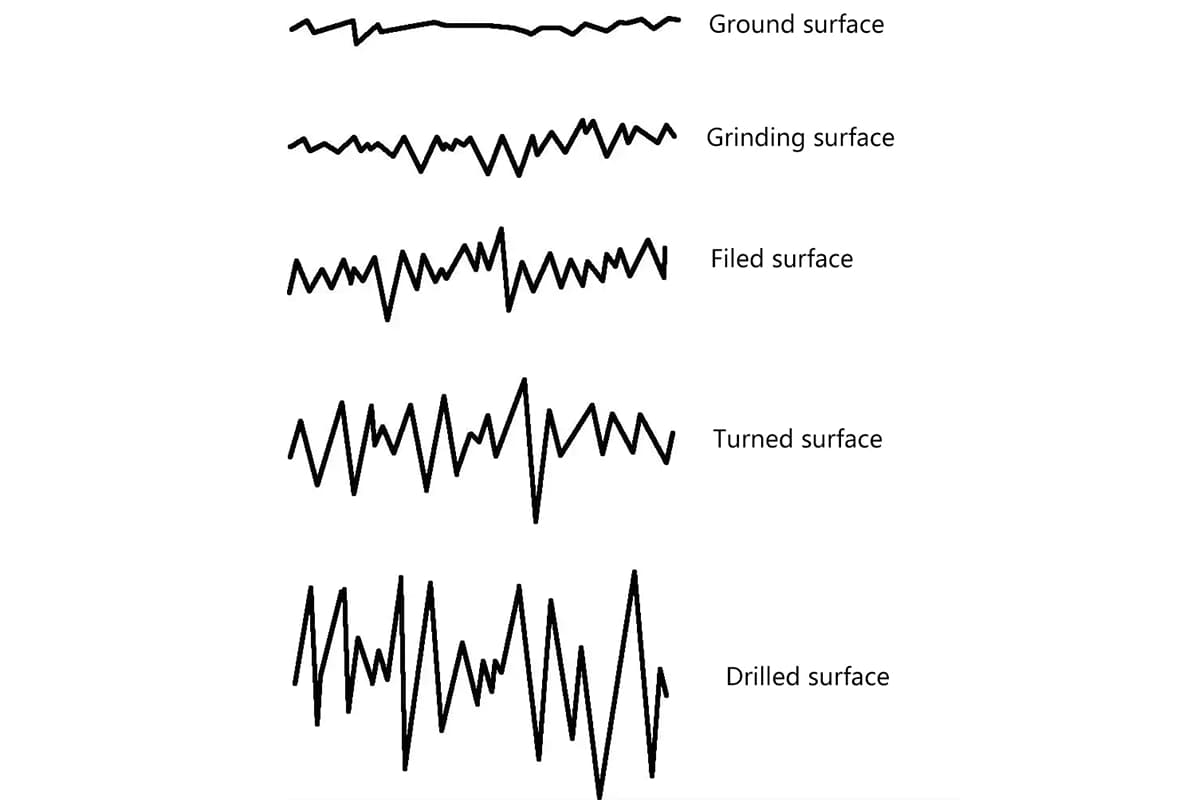
Secondly, a grinding wheel with suitable granularity should be selected, and the feed amount during grinding should be strictly controlled. Polishing should be carried out after grinding. At the same time, improving the quality of lubrication, reducing friction, and increasing the surface hardness of the punch die to above 61HRC can also help.
Longitudinal cracks and central splits that develop upward from the working end face, as shown in Figures 9-6b and 9-6c, are mostly caused by material defects such as uneven carbide distribution and excessive material segregation. This is because uneven carbide distribution increases the brittleness of steel and reduces its strength. During forging, material segregation is generally controlled to be below Level 3.
This is achievable for small diameter rods. For large diameter rods, it is necessary to eliminate excessive carbide segregation through strict cross forging processes. The corner cracks shown in Figures 9-6d and 9-6e are caused by too small fillets at the connecting parts or unsmooth joints.
Therefore, designing the connecting parts with fillets, careful machining and polishing to ensure smooth transitions and no stress concentration, are effective measures to prevent corner cracking.
Cracks that occur radially on the working end face and tail end face of the convex mold are shown in Figure 9-7. The cracks that occur at the working fillet of the convex mold are superficial minor cracks. These cracks often start from a very small abrasion, scratch, or metal adhesion pull injury, gradually expanding from extremely thin lines into micro-cracks.
a) Cracks at the working radius
b) Cracks on the working end face
c) Cracks on the tail end face
Therefore, reducing the surface roughness and increasing the hardness of the fillet area, using high-quality lubricants to prevent metal adhesion, can avoid such cracks. The network cracks on the working end face of the convex mold are caused by thermal fatigue due to the thermal effect during extrusion.
Sometimes, when the grinding amount is too large and the feed speed is too fast, turtle cracks caused by overheating of the surface can also develop into network cracks during extrusion. Therefore, when grinding the forming end face, a coarse-grained grinding wheel should be used.
Close to the finished product, the grinding amount should be small each time, and the tempering treatment, nitrocarburizing, chrome plating and other surface treatments should be checked. On the tail end face of the convex mold, sometimes end cracks similar to network cracks occur as shown in Figure 9-7c.
This surface network, longitudinally developing cracking phenomenon, is caused by uneven end faces, uneven material, or uneven convex mold pads, center collapse deformation, and poor end face contact. Therefore, the tail end face of the convex mold should be flat, parallel to the working end face, and use convex mold pads with sufficient thickness and strength to increase its rigidity and prevent deformation.
The causes and preventive measures for convex mold bending, fracture, and crack damage are shown in Table 9-3.
Table 9-3: Causes and Preventive Measures for Bending, Fracturing, and Cracking Damage in Convex Molds
| Forms of Damage | Main Characteristics | Causes of Formation | Preventive Measures | |
| Transverse Cracks | Fracture | 1)The fracture surface is slanted. 2)There are noticeable tear stripes at the fracture point. 3)The fracture occurs at the transition area. 4)It happens suddenly. | 1) The uneven end face of the blank generates a lateral force during extrusion, causing the convex mold to bend and break. 2) The large gap between the blank and the mold cavity results in uneven metal flow during extrusion, causing the convex mold to break under an unbalanced eccentric load. 3) The convex mold is installed off-center or tilted, and it’s not aligned with the concave mold. 4) The transition area of the convex mold has a too small fillet radius or is not smoothly connected, which leads to stress concentration and breaks the mold. 5) There are knife marks, grinding marks, scratches, and quenching cracks in the transition area of the convex mold. 6) The convex mold is elongated, and the length-to-diameter ratio of the working part is too large. 7) The improper selection of mold material and high heat treatment hardness increase brittleness due to insufficient tempering. 8) The equipment precision is poor, and the rigidity is low. | 1) Increase the shaping process to improve the precision of the blank. 2) Control the gap between the blank and the mold cavity to be within 0.1mm. 3) Improve installation precision by adopting effective guiding methods. 4) Increase the fillet radius as appropriate, and polish after machining until the surface roughness Ra is less than or equal to 0.4μm. 5) Finish machining and polish to remove processing traces and scratches. 6) Shorten the length of the convex mold as much as possible, especially the ratio of the effective length of the working part to its diameter, which should be controlled below 4. 7) Choose high-speed steel with excellent toughness to make the convex mold, adopt low-temperature quenching with sufficient tempering to increase the toughness of the convex mold. 8) Use a high-precision, high-rigidity, large-tonnage dedicated extrusion machine. |
| Tensile Break | 1) The fracture surface is flat. 2) The fracture resembles the appearance of gray cast iron and has a glossy finish. 3) The fracture is located at the transition area of the cross-section. | 1) At the junction of the radius and straight line, there are rough tool marks and sharp linear scratches. Due to repeated action, fatigue cracks occur and expand into circular cracks, eventually causing a break. 2) The punch is subjected to excessive pressure. 3) The compressive strength of the punch material is insufficient. 4) Poor lubrication results in excessive friction, leading to the punch breaking during material removal. | 1) Carry out meticulous machining to remove tool marks, cutting scars, and scratches. 2) Opt for high-quality materials to enhance the compressive strength and load-bearing capacity of the punch. 3) Use superior lubricants to reduce friction. | |
| Longitudinal crack. | Micro-cracks | 1) On the cylindrical surface of the working belt. 2) Located on the surface layer. 3) Minor and fine. | 1) The surface of the punch working belt is unsmooth, rough, and scratched. 2) The surface hardness of the punch is insufficient. 3) Overheating of the punch leads to surface softening. 4) Poor lubrication results in high surface friction, causing metal to stick to the punch and scratch its surface. | 1) During grinding, use a grinding wheel of appropriate granularity and control the feed amount to prevent micro-cracks caused by overheating. 2) Carry out precision machining and polishing until the surface roughness is Ra ≤ 0.4μm. 3) Use high-speed steel with excellent heat hardness for making the punch, ensuring a hardness above 61 HRC after quenching. 4) Use superior lubricants. |
| Longitudinal Cracking | 1) Along the axial direction. 2) Located at the central position. 3) Obvious cracking. | 1) Severe segregation of the material. 2) Uneven distribution of carbides. 3) Excessive residual austenite. | 1) Opt for materials of high-quality with uniform composition. 2) Adopt forging processes, limiting carbide segregation to a level below 3. 3) Implement cryogenic treatment to stabilize residual austenite. | |
| Radial crack | Micro-cracks | 1) Working end face. 2) At the radius of the fillet. | 1) Heat fatigue leading to mold surface softening. 2) Large grinding allowance and fast feed speed, leading to micro-cracks due to surface overheating. 3) Surface decarburization during heat treatment. 4) Metal adhesion causing the convex mold surface to be drawn, with linear scratches extending into cracks. | 1) Implement nitrocarburizing treatment. 2) Use coarse-grained grinding wheels, reducing the grinding feed rate as you approach the final dimensions. 3) Control the heat treatment temperature. 4) Lower the surface roughness of the convex mold, increase its hardness, and refine the machining process, polishing to a surface roughness of Ra ≤ 0.4μm. |
| Center cracking. | 1) On the tail end face. 2) Radiating radially from the center. | 1) Material structure is uneven, with severe carbide segregation. 2) The tail end face of the convex mold is uneven, leading to unbalanced stress. 3) The convex mold pad is thin with a small supporting area. 4) The convex mold pad collapses and deforms, causing the center part of the mold tail end to be unsupported. | 1) Utilize the forging process to keep carbide segregation under level 3. 2) The tail end of the punch must be flat; the presence of a peak hole is not permissible. 3) Increase the thickness of the backing plate to enlarge its support area. 4) Regular inspections of the backing plate are necessary, and upon deformation, it should be re-ground or replaced. | |
Local damage can occur at the working part of the punch, such as flanging and peeling. Shattering and pulverizing damage, on the other hand, are forms of total damage. They are sudden and highly destructive. Metal adhesion and galling are the most common types of die sticking phenomena. Die sticking can easily scratch the working surface of the punch, affecting the quality of extruded parts.
When die sticking is severe, it becomes difficult to unload the material, the working conditions worsen, and the extrusion process cannot proceed normally. The causes and prevention measures for these three types of damage are shown in Table 9-4.
Table 9-4: Causes of Punch Damage and Preventive Measures
| Types of Damage | Key Characteristics | Causes of Formation | Preventive Measures |
| Flanging | 1) Edge curling 2) Edge defect | 1) Inappropriate material selection 2) Unreasonable heat treatment process 3) Edge overheating leading to softening 4) Micro-cracks at the edge | 1) Choose materials with minimal segregation. 2) Implement multiple tempering processes to prevent increased brittleness of the cutting edge. 3) During grinding operations, avoid overheating or burning the cutting edge. |
| Peeling | 1) Local collapse and loss of chunks 2) Flake-like | 1) Accumulation of carbides in the material, forming a net-like structure 2) Uneven material structure with local defects 3) Improper heat treatment leading to excessive brittleness 4) Local overheating and burning during grinding | 1) Opt for high-quality materials with minimal carbide segregation and homogeneous structure. 2) Implement multiple tempering processes, each typically lasting for more than 1.5 hours. 3) Use coarse-grained grinding wheels and control the feed rate during grinding. |
| Shattering | Pulverizing | 1) Insufficient tempering leading to excessive hardness and increased brittleness in the punch die. 2) The instantaneous compressive force surpassing the punch die’s compressive strength. 3) Obstruction in the removal of excess material. 4) Misalignment of tools, causing the die set to deviate from the center. 5) Operator error, such as placing two workpieces at once. | 1) Implement multiple tempering processes to keep the hardness of the punch die below 63 HRC. 2) Choose materials with high compressive strength and excellent toughness for the fabrication of the punch die. 3) Avoid closed-die forging as much as possible to ensure smooth removal of excess material. 4) Pay close attention during operation, constantly checking for tool looseness or other abnormalities. |
| Galling Adhesion | 1) Formation of metal spalling 2) Surface scratches, unevenness 3) Presence of metal particles on the surface | 1) The workpiece is not clean and contains impurities. 2) The die is not smooth and has low hardness. 3) Poor lubrication effects. | 1) The workpiece surface should be clean, free of impurities, foreign matter, and oxidation. 2) Carefully grind and polish the die cavity to a surface roughness of Ra ≤ 0.4 µm. 3) Use high-strength, high-hardness steel or hard alloys for the die. 4) Use excellent lubrication formulas and improve operating procedures. |
Cold extrusion die cavities are not as prone to damage as die punches. Common forms of die cavity damage include cracking, longitudinal fissures, transverse fissures, and general wear.
Cracking is a prevalent form of early die damage, primarily observed as longitudinal cracking in the inserts, as shown in Figure 9-8. The primary causes of longitudinal cracking in the inserts are insufficient pre-stress, or due to the insert’s wall thickness being too thin, excessive roundness error, and insufficient strength.
To prevent this, it’s crucial to adequately increase the interference amount and the thickness of the die cavity inserts. When using hard alloy inserts, the roundness error of the outer diameter must be controlled to within 0.005mm.
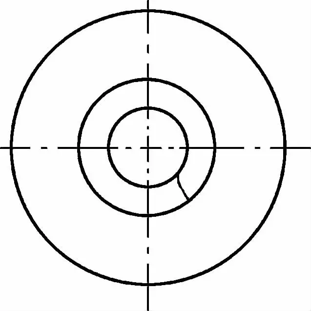
As shown in Figure 9-9, fissures occur on the inner surface of the die cavity. Initially, they don’t resemble cracks or heat-seizure scratches. However, with an increase in the number of machining operations, countless longitudinal scratches appear, gradually developing into a network of fissures that eventually lead to peeling.
These fissures are of a fatigue nature and are particularly likely to occur when lubrication conditions deteriorate, and pre-stress is insufficient. Therefore, improving the quality of lubricants and appropriately increasing the interference amount can help reduce longitudinal fissures.
Using nitrocarburizing treatment to enhance the surface hardness of the die, or substituting hard alloys for general tool steel in making the die cavity, can entirely eliminate the fissures shown in Figure 9-9a.
a) Cracks on the Inner Surface of the Cavity
b) Cracks on the Working Edge
1 – Initial Scratches 2 – Network of Cracks 3 – Delamination 4 – Longitudinal Cracks
The longitudinal fissures shown in Figure 9-9b occur at the working edge band position and also gather on the inner surface of the die cavity. Although they have certain depth, they don’t penetrate and primarily concentrate on the surface layer.
These fissures are mainly due to the presence of residual oxides on the blank surface causing poor lubrication, leading to die sticking, or caused by the softening of the die surface. Therefore, maintaining the cleanliness of the blank, enhancing the lubrication treatment effect, implementing nitrocarburizing treatment to improve the hardness of the die cavity, or using hard alloys for die cavity inserts can effectively eliminate these fissures.
There are two common types of transverse cracks, as shown in Figure 9-10. The transverse cracks in the die shown in Figure 9-10a occur at the transition section of the cross-section. If the radius of the fillet at the transition area is appropriately increased, or if the die is split laterally into two parts at this point, these cracks can be eliminated.
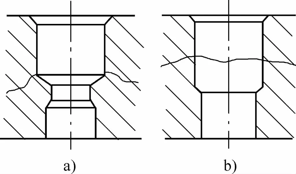
a) Cracks at the Transition Location
b) Cracks on the Boundary between the Guiding and Forming Parts
The transverse cracks shown in Figure 9-10b occur on the boundary between the guiding part and the forming part of the die, i.e., the parts of the die that are subjected to repeated actions. During the extrusion process, the load applied by the punch onto the die is a cyclical repeating load, thus the radial elastic deformation of the die also fluctuates periodically.
Due to this prolonged repetition, transverse cracks appear on the interface. Clearly, the occurrence of cracks is directly related to excessive deformation and insufficient strength of the die, and also related to the contact condition of the fit surface.
Therefore, increasing the ratio of the inner to outer diameter of the insert and the entire die, appropriately increasing the interference amount, ensuring uniform contact of the fit surface, or using a die with multiple press jackets can eliminate transverse cracks.
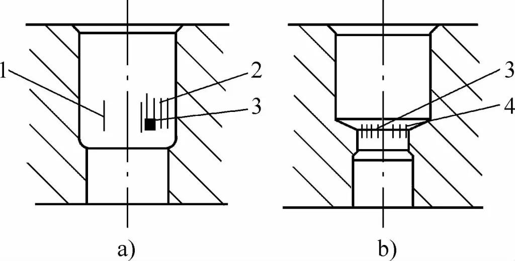
As depicted in Figures 9-11, the corner collapse A and delamination B occurring on the die cavity and working surface represent a common form of damage in cold extrusion dies. This type of delamination damage often occurs at the edges of the working blade, the edge ridge, or the hole mouth. These are areas of stress concentration and are comparatively weaker.
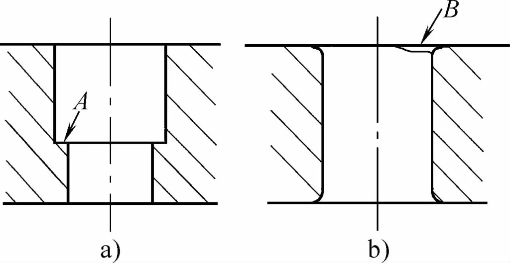
a) Corner collapse
b) Delamination peeling
Improper selection of fillet radius or poor material toughness can lead to local delamination. Metal peeling can also occur when there are local defects or softening due to local overheating. Therefore, using materials of high toughness, choosing an appropriate fillet radius, and utilizing quality lubricants can significantly reduce and prevent occurrences of delamination.
The damage forms of the pre-stress ring in the compound die mainly include longitudinal cracking and permanent deformation.
Figure 9-12a shows two types of longitudinal cracking scenarios in the pre-stress outer ring: one is the natural cracking that occurs within a few hours after assembly, and the other type occurs under load, after extruding a few, dozens, or even hundreds of pieces.
The main cause of this cracking is that the assembly’s pre-interference is too large, causing the tensile stress generated by the pre-stress in the inner surface of the outer ring to exceed the yield strength of the outer ring material, that is, the pre-stress outer ring is subjected to excessive tensile stress, or due to the insufficient strength or excessive hardness of the outer ring itself.
In situations where a single pre-stress outer ring is pre-tightened, if the hardness of the outer ring is close to 50HRC, it may cause natural cracking, i.e., the outer ring has the risk of suddenly cracking on its own during the placement period after assembly, so the hardness of the single-layer outer ring must be controlled below 45HRC.
In the case of using double pre-stress outer rings, if the hardness of the outer ring is below 40HRC, the middle ring hardness can be 50HRC. However, during assembly, if the outer ring and the middle ring are not first assembled together, it is also dangerous. Therefore, to prevent outer ring cracking, the interference amount and the hardness of the outer ring should be strictly controlled, and the assembly method should be reasonable.
When machining holes for fixation on the pre-stress ring, as shown in Figure 9-12b, because these holes will greatly reduce the strength of the outer ring and cause stress concentration, cracking often occurs at the drilling location during extrusion, so try to avoid making holes for fixing the mold or other holes on the pre-stress ring.
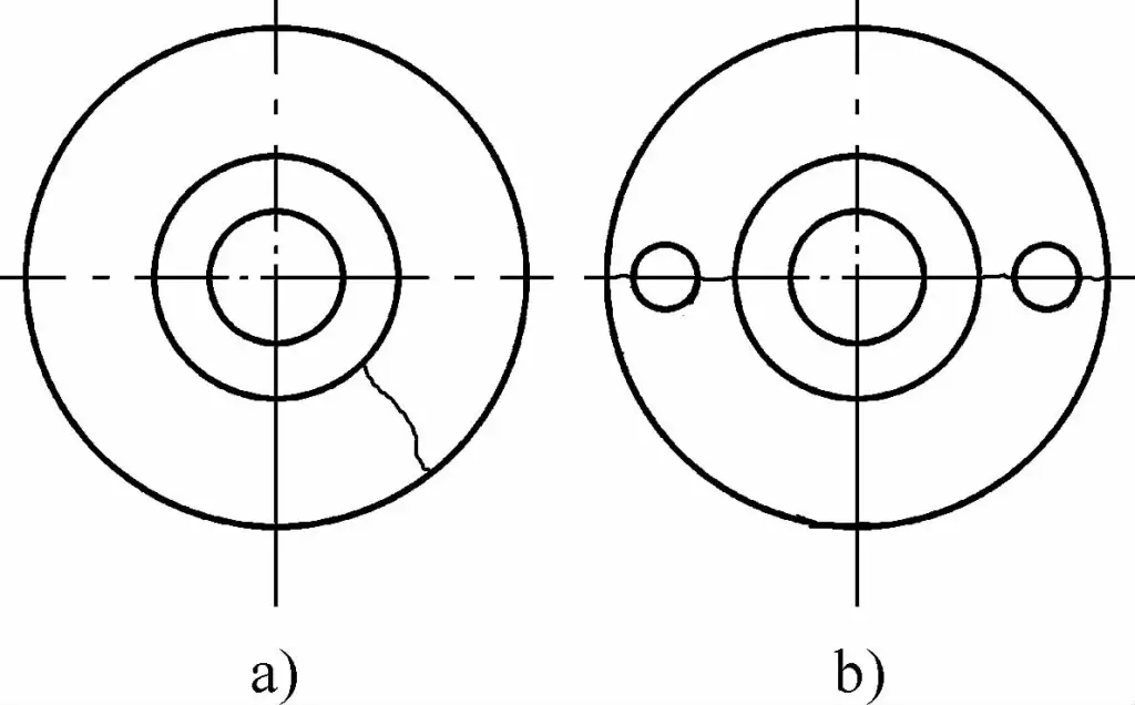
(a) Cracking in the Outer Ring
(b) Cracking at the Drilling Point
Permanent deformation can occur due to inappropriate material selection for the prestressed ring, low hardness or strength after heat treatment, or excessive interference during assembly resulting in excessive radial pressure.
Therefore, by using superior materials, implementing reasonable heat treatment processes to enhance hardness and strength, or by optimally choosing the diameter and interference of the prestressed ring to ensure the preloading does not exceed the yield strength of the material, such permanent deformation can be prevented.
There are primarily two forms of damage to the pressure plate due to various reasons: radial cracks and permanent deformation.
Radial cracks refer to radiating cracks generated along the radial direction of the pressure plate, as shown in Figure 9-13. The causes of radial cracks include:
① poor material of the pressure plate and low hardness;
② uneven bearing surface (see Figure 9-13a) or too small die diameter (see Figure 9-13b);
③ the pressure plate undergoes multiple repeated elastic deformations, leading to fatigue cracks.
Preventive measures to eliminate these cracks include:
① increasing the hardness of the pressure plate;
② increasing the thickness of the pressure plate or the die diameter;
③ adding a reinforcement ring on the exterior of the pressure plate to enhance its strength;
④ ensuring the parallelism of the upper and lower planes of the pressure plate during processing, with no unevenness.
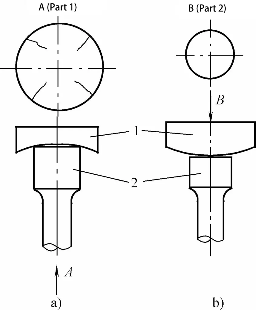
a) Indentation
b) Protrusion.
1 – Pressure Plate
2 – Punch
The reasons for the permanent deformation of the bearing surface of the pressure plate are:
① the strength of the pressure plate is not sufficient;
② excessive unit extrusion force;
③ insufficient thickness of the pressure plate or too small die diameter.
Preventive measures to avoid this kind of permanent deformation include:
① using high-quality materials to make the pressure plate;
② adopting a reasonable heat treatment process to enhance the hardness and strength of the pressure plate;
③ increasing the thickness of the pressure plate and the die diameter to improve the compressive capacity of the pressure plate;
④ using multi-layer pressure plates to alleviate the high pressure transmitted from the convex and concave dies.