Hot vs Cold Extrusion: Key Differences and Applications
When it comes to shaping materials into precise forms, extrusion stands out as one of the most versatile manufacturing processes.…
In the cold extrusion process, due to a series of technological factors, the extrusion force is difficult to calculate accurately. This is particularly the case for complex-shaped parts, for which there are no well-established calculation methods or practical, reliable formulas or charts.
Currently, common methods to calculate the extrusion force during cold extrusion include simple calculations, graphical calculations, and graphical analysis methods.
The approximate value of the unit extrusion force for various different materials can be looked up in Table 3-13, and then multiplied by the actual working area of the extrusion to obtain an approximate extrusion force. The formula is:
P = pA (3-9)
Where:
Practice has proved that the estimation made with the above empirical data is close to the actual situation and can basically meet the requirement.
Also known as the nomogram method, this approach assumes a uniform deformation state of the metal during the cold extrusion process. It takes into account factors such as the reduction rate of the extrusion cross-section, the size of the blank, the mechanical properties of the material, and the shape of the working part of the die.
Another condition for using the graphical calculation method is that the blank undergoes softening, surface treatment, and lubrication before extrusion.
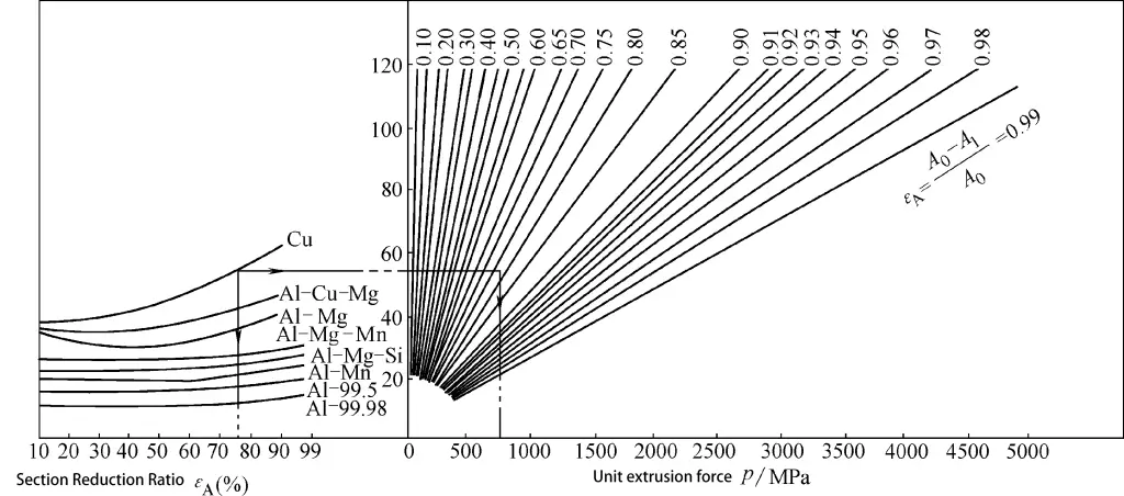
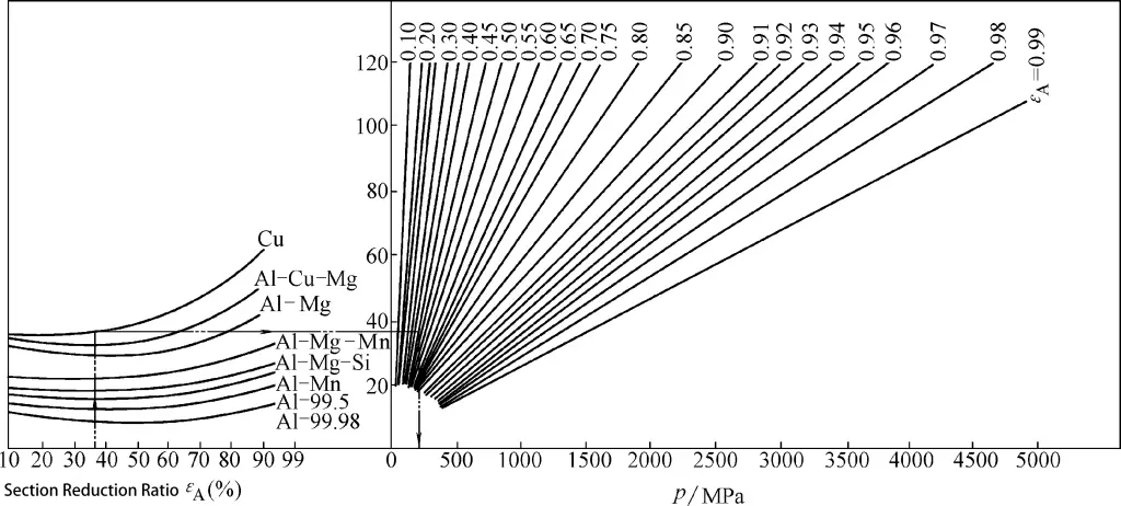
The graphical calculation of unit extrusion force for solid extrusion is shown in Figure 3-9. The graphical calculation of unit extrusion force for hollow extrusion is shown in Figure 3-10.
Table 3-13 Approximate Value of Unit Extrusion Force During Extrusion
| Material | Deformation State | |||||
| Direct Extrusion | Indirect Extrusion | Closed Die Forming | ||||
| Cross-Sectional Reduction Rate εA (%) | Unit Extrusion Force ρ/MPa | Cross-Sectional Reduction Rate εA (%) | Unit Extrusion Force ρ/MPa | Cross-Sectional Reduction Rate εA (%) | Unit Extrusion Force ρ/MPa | |
| Pure Aluminum | 97 ~ 99 | 600 ~ 800 | 97 ~99 | ≈800 | 30 ~ 50 | / |
| Aluminum Alloy | 92 ~ 95 | 800 ~ 1000 | 75 ~82 | 800 ~ 1200 | 30 ~ 50 | 1000 ~ 1600 |
| Brass | 75 ~87 | 800 ~ 1200 | 75 ~ 78 | 800 ~ 1200 | 30 ~ 50 | 1000 ~ 1600 |
| 10 Steel | 50 ~ 80 | 1400 ~ 2000 | 40 ~75 | 1600 ~ 2200 | 30 ~ 50 | 1000 ~ 1600 |
| 30 Steel | 50 ~ 70 | 1600 ~ 2500 | 40 ~ 70 | 1800 ~ 2500 | 30 ~ 50 | 1600 ~ 2000 |
| 50 Steel | 40 ~ 60 | 2000 ~ 2500 | 30 ~ 60 | 2000 ~ 2500 | 30 ~ 50 | 1800 ~ 2500 |
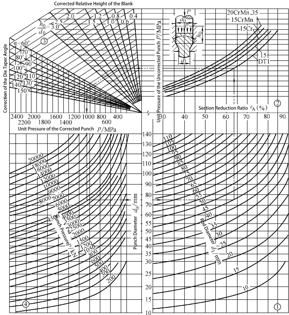
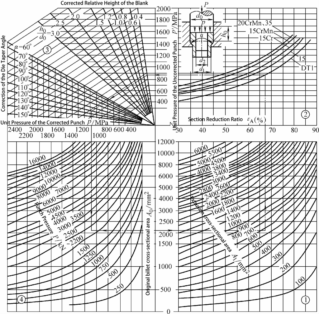
Graphical Method: Proceed in the direction indicated by the arrows in the figure to find the required unit extrusion force and total extrusion force.
For instance, to find the unit and total extrusion force during the direct extrusion of a solid piece: Assume the billet diameter d1 is 75mm, the extrusion rod diameter d0 is 45mm, the billet height h is 110mm, and the die cone angle α is 90 degrees. The material is pure iron DT1. Referencing Figure 3-9, we find the unit extrusion force p is 1050MPa, and the total extrusion force P is 4600kN.
Similarly, to find the unit and total extrusion force during the direct extrusion of a hollow piece: Assume the billet diameter d0 is 95mm, the extruded piece’s outer diameter d1 is 85mm, inner diameter d2 is 80mm, the billet height h0 is 50mm, and the die cone angle α is 120 degrees. The material is pure iron DT1. Referencing Figure 3-10, we find the unit extrusion force p is 1080MPa, and the total extrusion force P is 2230kN.
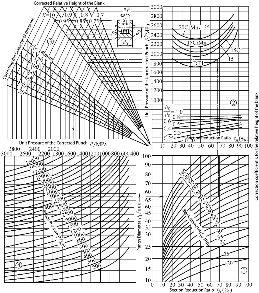
The unit extrusion force and total extrusion force for backward extrusion of steel cup-shaped parts can be graphically calculated as shown in Figure 3-11.
How to use the chart: Follow the direction of the arrow in the image to find the required unit extrusion force and total extrusion force.
For example, given a billet diameter (d0) of 70mm, a punch diameter (d1) of 58mm, a billet height (h0) of 35mm, and a material of pure iron (DT1), from Figure 3-11, we can determine that the unit extrusion force (p) is 1660 MPa, and the total extrusion force (P) is 4400 kN.
It should be noted that the chart only lists a portion of metal materials. For unlisted metals, you can find a metal with a similar carbon content in the chart, then multiply the ratio of the tensile strengths (Rm) of the two metals after annealing by the extrusion force found in the chart to get the extrusion force of the extruded material.
For instance, to find the unit extrusion force of GCr15 bearing steel in forward extrusion, we know that the carbon content of GCr15 and 35 steel is not similar, and the Rm of GCr15 after annealing is 650~750 MPa, while the Rm of 35 steel after annealing is 530~550 MPa.
From Figure 3-9, the unit extrusion force (p) for a 35 steel part of corresponding size is 2000 MPa, so the unit extrusion force for GCr15 is approximately 2000 x (750/550) MPa, which is about 3000 MPa.
The unit extrusion force graphs for direct extrusion of solid and hollow pieces, as well as reverse extrusion of cup-shaped pieces in nonferrous metals, are shown in Figures 3-12 to 3-14. In these graphs, σ represents the average deformation resistance of the material; the deformation efficiency varies with the blank height and the cross-sectional reduction rate.
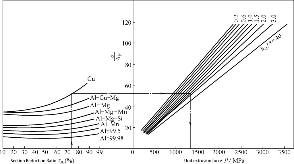
Method for Reading the Graph: The required unit extrusion force can be obtained by following the direction indicated by the arrows in the graph.
For example, to calculate the unit extrusion force of a solid piece directly extruded from copper material. Given a blank diameter (d0) of 50mm and an extruded rod diameter (d1) of 24mm, we can refer to Figure 3-12 to find that the unit extrusion force (p) is 760MPa.
Graphs made considering the type of metal material as a factor cannot possibly list all materials. For unlisted materials, it’s inconvenient to convert based on their carbon content. Figures 3-15 and 3-16 display graphs created with the parameter of Vickers Hardness (HV) after annealing of steel materials. As the hardness values in these graphs vary, the resulting unit extrusion force should also vary accordingly.
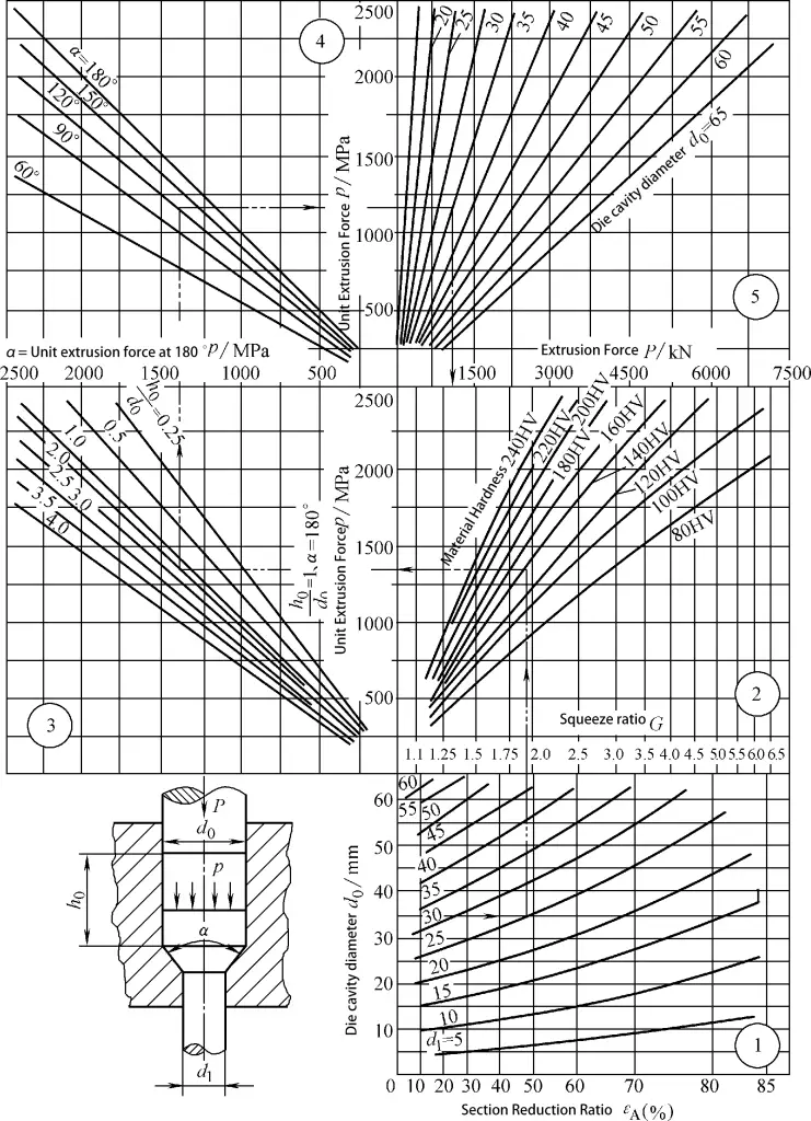
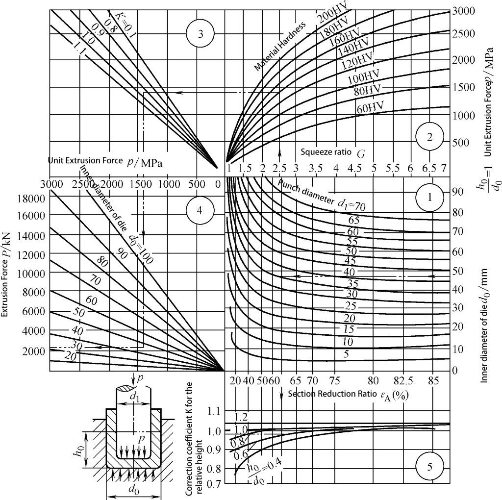
Chart Reference Method: Follow the direction of the arrows in the chart to find the required unit extrusion pressure and total extrusion pressure.
For instance, to find the unit extrusion pressure and total extrusion pressure for direct extrusion of a solid piece.
Given that the blank diameter d0 is 35mm, height h0 is 35mm, extruded part diameter d1 is 25mm, and the material’s Vickers hardness is 140HV, with a die angle α of 120°; referring to Figure 3-15, the unit extrusion pressure p can be found to be 1220MPa, and the total extrusion pressure P is 1180kN.
The extrusion pressure of simple rod-shaped or cup-shaped pieces can be estimated using existing empirical formulas or charts. However, there is no comprehensive calculation method or practical and reliable column charts for the extrusion pressure of complex-shaped workpieces.
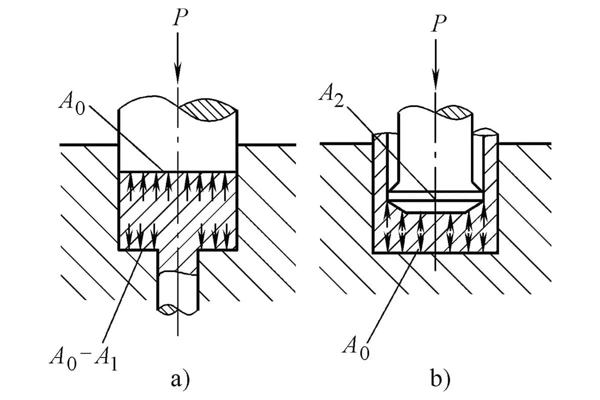
For example, there are no ready-made formulas or charts that can be directly adopted to calculate the extrusion pressure of the part shown in Figure 3-17 under direct extrusion. Therefore, it is necessary to specifically analyze and decompose it into a simple cup-shaped piece for calculation, as shown in Figure 3-18.
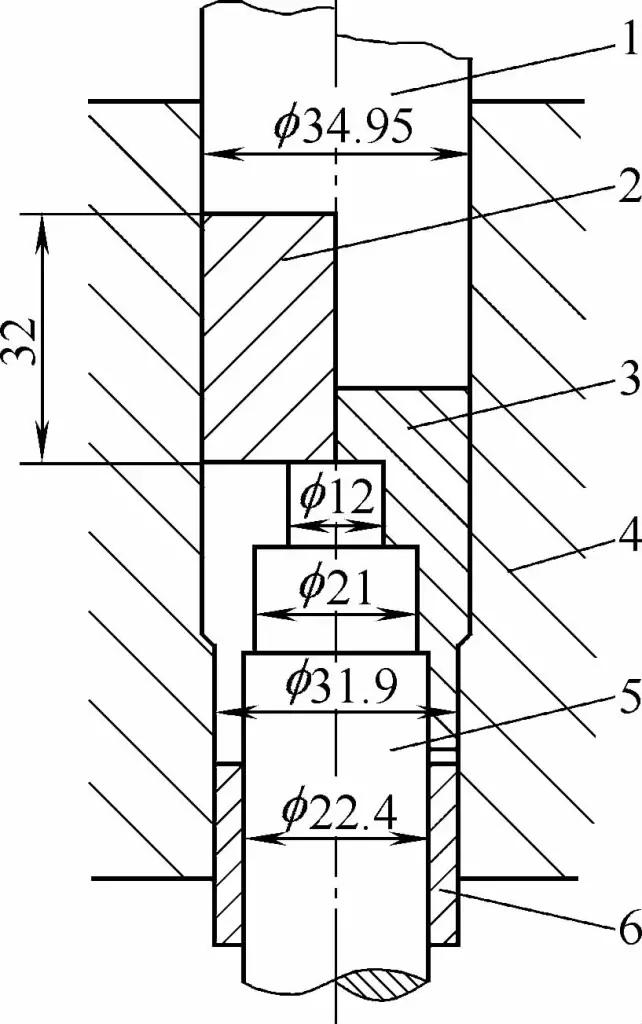
1—Punch
2—Blank
3—Extruded Part
4—Die
5—Lower Punch
6—Annular Ejector Sleeve
When calculating, the external step 4 of the extruded part shown in Figure 3-18a is first simplified into a straight-walled cylindrical part (see Figure 3-18b), this is the first shape simplification. As the sizes of holes 2 and 3 are relatively similar, the two holes can be considered as one large hole, turning into the shape shown in Figure 3-18c, this is the second shape simplification.
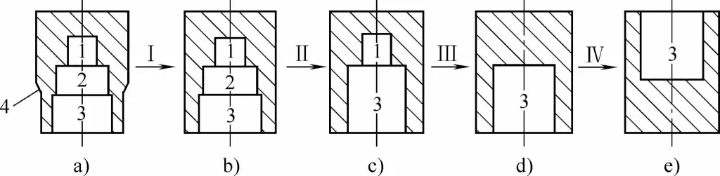
If small hole 1 is also considered separately, then the shape after the third simplification is a simplified direct extrusion cup-shaped piece (see Figure 3-18d). Alternatively, calculations can start with a cup-shaped piece under reverse extrusion (see Figure 3-18e).
At this point, the final simplification process is completed. In this way, after specific analysis and simplification, a complex part with an internal and external step-like shape can be treated as a typical reverse extrusion cup-shaped piece to calculate the required extrusion pressure, which is much simpler and easier.
In the calculation, we should start from the final simplified shape and work our way back. During the calculation process, we should consider the impact of each shape on the extrusion force, and thus gradually determine the required extrusion force. The extrusion force of the reverse extruded cup-shaped piece (see Figure 3-18e) is denoted as P, and its value can be obtained from existing formulas and charts, which we will not elaborate on here.
If the cup-shaped piece is processed using the direct extrusion method (see Figure 3-18d), the extrusion force would be 15% to 20% higher, as shown in Figure 3-19. Hence, the extrusion force at this point would be 1.2P. Generally, the presence of a stepped hole will increase the extrusion force by about 20%, as seen in Figure 3-20. Therefore, the extrusion force for the shape shown in Figure 3-18c would be 1.44P (1.2P x 1.2).
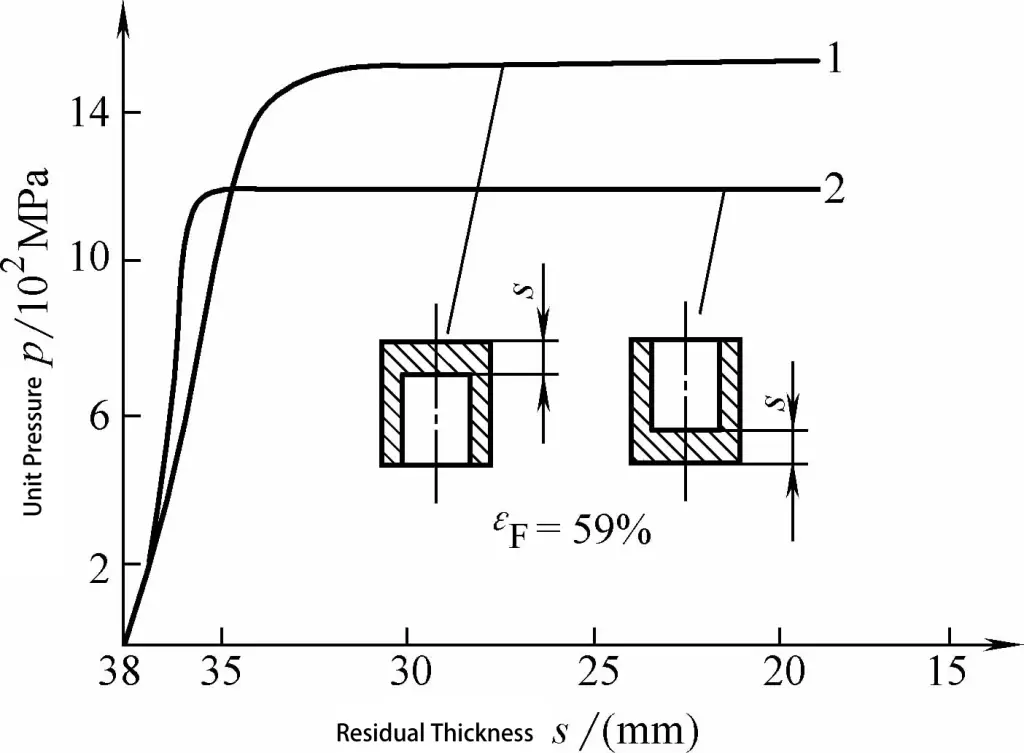
1. Indirect Extrusion with Stepped Holes
2. Indirect Extrusion with Straight Holes
Since the sizes of the stepped holes (holes 2 and 3) vary slightly, their impact can be neglected. That’s why the extrusion force for the shape shown in Figure 3-18b remains 1.44P. The influence of the external step 4 (see Figure 3-18a) is considered as a 10% increase in extrusion force, so the extrusion force for the shape shown in Figure 3-18a becomes 1.58P (1.44P x 1.1).
Assuming the blank size of this piece is 34.94mm x 32mm, and the deformation degree is 40% (Figure 3-18e), the extrusion force obtained from the general chart is approximately 800kN. Therefore, the required extrusion force for the direct extrusion stepped part shown in Figure 3-17 is 1264kN (800kN x 1.58).
Thus, the formula for calculating the extrusion force of complex shaped parts is:
P = P1C1C2 (3-10)
where:
The complexity factor is determined by the complexity of the extrusion piece shape, mainly considering the impact of the stepped shape on the extrusion force. It can be approximately selected based on relevant design materials and experimental curves. The exact choice of the complexity factor C1 is closely related to the experience of the designer.
The deformation method impact factor mainly considers the difference in deformation force between direct extrusion, reverse extrusion, and the combination of the two. It is usually selected to be around a 20% increase, i.e., C2 ≈ 1.2.
Therefore, the graphical analysis process for calculating the extrusion force of complex shaped parts is:
1) Gradually simplify the complex shaped extrusion piece to a simple rod-shaped or cup-shaped piece, which serves as the initial shape for calculation.
2) Analyze the differences between each body and consider them as independent factors.
3) Comprehensively analyze the graphic decomposition and simplification process, and use it as a technological model for calculating the actual cold extrusion force of the extrusion piece.
Using graphical analysis to solve for extrusion force is a simple, practical, and effective engineering calculation method. The estimation accuracy of this method is sufficient to meet the requirements.
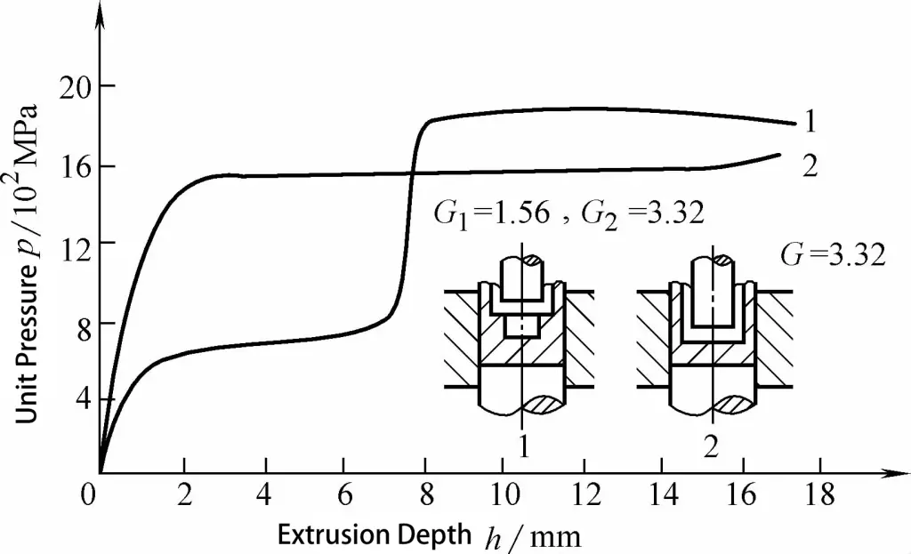
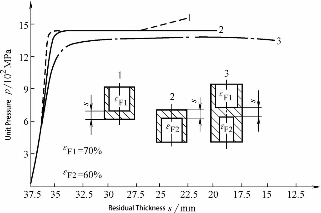
The calculation method for the extrusion force of compound extrusion is: the required extrusion force for compound extrusion is equal to or slightly lower than the value needed for unidirectional extrusion with a smaller degree of deformation, as seen in Figures 3-21 and 3-22. This means that when calculating the pressure for compound extrusion, we only need to solve for the extrusion force value of the direction with a smaller degree of deformation.
1. Indirect Extrusion
2. Direct Extrusion
3. Composite Extrusion
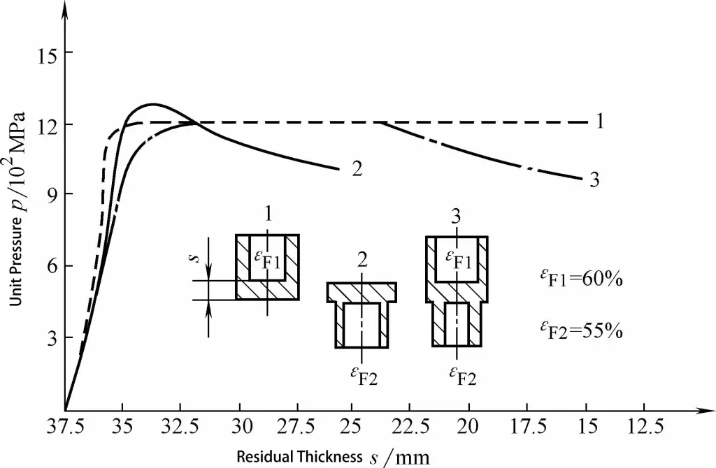
1. Indirect Extrusion
2. Direct Extrusion
3. Composite Extrusion
When composite extrusion doesn’t restrict the size in a particular direction, i.e., when the metal freely flows in both directions with the die open at both ends, the pressure is defined as:
Pcomp=Pdirect (Pdirect<Pindirect) (3-11)
Pcomp=Pindirect(Pindirect<Pdirect (3-12)
Where:
When composite extrusion restricts the size in a particular direction, i.e., when a closure extrusion is necessary at one end as the extrusion process is about to end, the pressure is defined as: