Copper Alloy Forging: Techniques & Tips
Forging copper alloys involves mastering precise heating techniques and handling unique challenges. This article breaks down key aspects of the…
Why is copper alloy forging so essential in modern manufacturing? This article explores the intricate processes involved in preparing, heating, and forging copper alloys, emphasizing the specific techniques required to handle different types of copper alloys, such as brass and bronze. It also details the necessary steps for billet preparation, deformation temperature management, and post-forging treatments. Readers will gain a thorough understanding of how to optimize forging practices for copper alloys, ensuring high-quality and reliable results in various applications.
By adding elements such as zinc, tin, lead, nickel, manganese, silicon, and aluminum to copper, copper alloys are formed. Copper alloys with zinc as the additive element are called brass, and those with tin or lead, silicon, etc., as the main additive elements are called bronze. In addition, there are other copper alloys such as white copper (copper-nickel alloy).
The raw materials for copper alloy forging mainly include cast chains and extruded rods.
Ingots are used as billets for large forgings, and they must undergo homogenization annealing before forging to improve plasticity. If there are defects on the surface of the ingot, they should be polished clean or peeled before forging.
If the ingot is used as a die forging blank, it can be directly forged after appropriate billet preparation without the need for repeated upsetting as in aluminum and magnesium alloys, because the plasticity of copper alloys is higher and the microstructure is not as complex as that of aluminum and magnesium alloys.
Extruded rods are suitable for medium and small-sized die forgings or free forgings. To eliminate internal residual stresses and prevent cracking, extruded rods must be annealed promptly after deformation.
Copper alloys are often cut with circular saws for high-quality copper alloy blanks, which can be directly machined on a lathe, with chamfering of the end faces to eliminate surface defects.
It is best to use electric heating for copper alloys, although flame furnaces can also be used. Heating copper alloys in a resistance furnace with a thermocouple to control the furnace temperature is quite accurate, while heating in a flame furnace results in larger temperature measurement errors.
The heating temperature for copper alloys is lower than that for steel, and it is difficult to ensure stable combustion at low temperatures using gas and heavy oil heating furnaces, which require nozzle adjustments. Therefore, it is best to use low-temperature burners.
In comparison, the fuel media heating furnace has some advantages. When a high-temperature coal-fired heating furnace needs to heat copper alloys, it can maintain a so-called “gentle fire” by reducing the amount of coal and air, unlike oil furnaces that can cool down rapidly due to unstable combustion processes.
The furnace gas composition of a heating furnace is best to be neutral, but it is difficult to obtain a neutral atmosphere in ordinary flame furnaces, often being slightly oxidizing or reducing. For all high copper alloys that are highly susceptible to oxidation at high temperatures, such as oxygen-free copper, low-zinc brass, aluminum bronze, tin bronze, and nickel silver, heating should generally be done in a reducing atmosphere.
High-oxygen copper alloys are not suitable for heating in a reducing atmosphere. Because the reducing atmosphere contains gases such as H2, CO, CH4, when the heating temperature exceeds 700°C, these gases will diffuse into the metal, forming insoluble steam or CO2 in copper. This steam has a certain pressure, trying to escape from the inside of the metal, resulting in tiny cracks inside the metal, making the alloy brittle, known as “hydrogen embrittlement.”
When heating pure copper, it is best to use a slightly oxidizing atmosphere, which can avoid “hydrogen embrittlement” and reduce the formation of oxide scale. High-zinc brass is suitable for heating in a slightly oxidizing atmosphere, which can prevent dezincification and severe oxidation.
Due to the good thermal conductivity of copper alloys, cold charge can be directly loaded at the highest furnace temperature and kept for a certain period of time, with the furnace temperature being 50-100°C higher than the initial forging temperature (flame furnace) or 30-50°C higher (electric furnace). The heating time can be calculated as 0.4-0.7min per millimeter of cross-sectional size (diameter or side length). Based on production experience, the heating times for some commonly used copper alloys are as shown in Table 1.
Table 1 Copper and Copper Alloy Heating Times
| Alloy Grade | Heating Time/(min/mm) |
| T1, T2, T3, T4, H96, H90, H85, H80, HSn90-1, QCr0.5, QSi1-3, QCd1 | 0.4 |
| H70, H68, H62, HAI77-2, HAl60-1-1, HAl59-3-2, HPb59-1, HPb61-1, HSn90-1, HSn62-1, HSn60-1, HMn58-2, HFe59-1-1, QSn4-3, QSn4-0.3, QA15, QA17, QMn5, QBe2 | 0.6 |
| HNi65-5, HSi80-3, H59, QSn7-0.2, QSn6.5-0.4, QSn6.5-0.1, QA19-2, QA19-4, QAl10-3-1.5, QAl10-4-4, QSi3-1 | 0.7 |
Note:
1. Heating time starts after the alloy is heated to the initial forging temperature.
2. The data in the table are for the first heating time required; subsequent heatings are half the time of the first heating.
3. The furnace temperature should be 30 to 100°C higher than the initial forging temperature of the alloy.
The initial forging temperature of copper alloys is lower than that of steel. Additionally, due to the presence of an intermediate temperature brittleness zone, the forging temperature range is much narrower than that of carbon steel, as shown in Table 2. Copper alloys have a brittleness zone between 250 and 650°C, which is due to the presence of impurities such as lead and bismuth in the alloy. These have very low solubility in the α-solid solution and form low-melting-point eutectics with copper, such as Cu-Pb and Cu-Bi, which are distributed in a network along the grain boundaries of the α-solid solution, thereby weakening the intergranular cohesion.
Table 2 Copper Alloy Forging Temperature Range
| Type of alloy | Alloy grade | Forging temperature / °C | Heating temperature +10&-20/ °C | Holding time / (min/mm) | |
| Start forging | End forging | ||||
| Brass | HPb59-1 | 720 | 650 | 720 | 0.6 |
| HPb61-1 | 810 | 650 | 810 | ||
| H62, H68 | 810 | 650 | 810 | ||
| H70 | 840 | 700 | 840 | ||
| H80 | 860 | 700 | 860 | ||
| H90 | 890 | 700 | 890 | ||
| H96 | 920 | 750 | 920 | ||
| Bronze | QAl9-2, QAl9-4 | 890 | 700 | 890 | 0.7 |
| QAl10-3-1.5 | 840 | 700 | 840 | ||
| QAl10-4-4 | 890 | 750 | 890 | ||
| QBe2.5 | 740 | 650 | 740 | 0.6 | |
| QSi1-3 | 870 | 700 | 700 | 0.7 | |
| QSi3-1 | 790 | 700 | 630 | ||
| QCd1.0, QMn5 | 840 | 650 | 650 | 0.6 | |
| QSn6.5-0.4 QSn7-0.2 | 790 | 700 | 700 | 0.7 | |
| Pure copper | T1, T2, T3, T4, T5 | 900 | 650 | 900 | 0.6 |
| White copper | B19 | 1000 | 850 | 1000 | |
When heated above 500°C, an a→a+β transformation occurs, with lead and bismuth dissolving in the β solid solution, thus improving plasticity. When the heating temperature exceeds the α+β→β transformation, at temperatures (~700°C), β grains grow rapidly, reducing plasticity. Therefore, copper alloy forging deformation mainly occurs within the temperature range of the α+β dual phase. Measures should be taken to prevent excessive heat loss from the material during copper alloy forging.
The tools and molds used for deformation should be preheated to a higher temperature. During free forging, preheat the operating tools to 200-250°C, act quickly during operation, and frequently turn the billet on the anvil to avoid excessive heat loss from the billet, allowing for a longer operation time within one heating. Before die forging, preheat the forging die to 150-300°C and minimize the residence time of the copper alloy in the mold. Otherwise, cracking may occur during forging.
For example, during punching, if the temperature of the punch is low, it can cause the temperature around the hole to drop and crack; if cutting the head in the brittle temperature zone, the fracture will appear coarse-grained, and if trimming immediately after die forging, it often tears the body of the forged part. Conversely, if trimmed after water cooling, this phenomenon does not occur.
On the other hand, if the final forging temperature is too high, it will cause grain growth, and unlike carbon steel, the grain growth in copper alloys cannot be refined by heat treatment, so when selecting forging deformation temperatures using Table 2, different values must be chosen based on different deformation conditions.
For example, QAl94 tire die forging cools faster than white forging. For the same alloy, the deformation temperature varies with stress state, degree of deformation, deformation speed, and other deformation conditions. Table 3 introduces the different deformation temperatures for the same copper alloy under different deformation conditions.
Table 3 Copper Alloy Deformation Temperature
| Alloy | Temperature/ °C | |
| Forging, Die Forging | Extrusion | |
| Copper | ||
| T2, T3, T4 | 800~950 | 775~925 |
| Brass | ||
| H96 | 700~850 | 830~880 |
| H90 | 800~900 | 820~900 |
| H80, H85, H70 | — | 820~870 |
| H68 | 700~850 | 750~830 |
| H62 | 650~850 | |
| HAI77-2 | — | 700~830 |
| HAl60-1-1 | 700~750 | |
| HAl59-3-2 | 700~750 | |
| HNi65-5 | 650~850 | 750~850 |
| HFe59-1-1 | 650~820 | 650~750 |
| HMn58-2 | 600~750 | 625~700 |
| HMn57-3-1 | 600~730 | |
| HSn90-1 | 850~900 | 850~900 |
| HSn70-1 | 650~750 | 650~750 |
| HSn62-1 | 680~750 | 700~750 |
| HSn60-1 | 700~820 | 780~820 |
| HPb59-1 | 640~780 | 640~780 |
| Bronze | ||
| QAl5 | 750~900 | 830~880 |
| QAl7 | 760~900 | 850~900 |
| QAl9-2 | 800~960 | 750~850 |
| QAl9-4 | 750~900 | |
| QAl10-3-1.5 | 700~850 | |
| QAl10-4-4 | 800~900 | 830~880 |
| QBe2 | 650~800 | 720~660 |
| QBe2.5 | 720~800 | |
| QSi3-1 | 600~780 | 825~875 |
| QSi1-3 | 800~910 | 850~900 |
| QSn4-0.25 | 800 ~920 | 750~800 |
| QSn6.5-0.4 | 680~770 | |
| QCr0.5 | — | |
| BZn15-20 | 750~825 | |
| BFe28-2.5-1.5 | 850~950 | |
To avoid coarse grains, it is required that each deformation of copper alloy forging is greater than the critical deformation amount, that is, more than 10% to 15%.
Most copper alloys are not sensitive to deformation speed and can be forged on presses or hammers, but it is preferable to forge on presses. Lead-containing brass is very sensitive to deformation speed, showing significant differences in plasticity during static and dynamic tensile deformation, and such alloys should be forged on presses.
Tin phosphor bronze and manganese bronze show significant thermal effects during forging. If the deformation speed is too fast, overheating can occur, and even burning.
The design principles for copper alloy die forgings and forging dies are the same as those for steel forgings. However, due to the lower friction factor between copper alloys and steel dies, the forging draft angle for copper alloys is smaller than that for steel. Due to the narrow forging temperature range and good thermal conductivity, multi-die membrane forging is generally not used, and pre-forging dies are rarely used due to good fluidity.
For complex-shaped forgings, they can be free-forged into blanks and then die-forged into shape. The surface roughness of the die cavity is generally Ra1.60 to Ra0.40μm. Copper alloys are very suitable for extrusion forming.
For leaded brass die forgings, if the degree of deformation is large and the deformation speed is fast, the thermal effect is significant, causing the temperature of the alloy to rise and melting the low-melting impurities in the alloy, destroying the intergranular bonds. Therefore, when designing forgings and formulating forging process specifications, the degree of deformation and deformation temperature should be reasonably determined based on specific conditions.
Since copper alloys are more sensitive to internal stress than carbon steel, if not eliminated, they will crack on their own during use, requiring the deformation temperature and amount of deformation to be relatively consistent throughout the forging. Therefore, during forging, the hammering should be light and fast, and the amount of hammering should not be too large. After the billet has undergone a certain degree of deformation, the amount of deformation can be appropriately increased.
When forging long shaft forgings, it is necessary to frequently turn the head during operation to keep the deformation temperature of each section similar in one heat. This results in a uniform microstructure and more consistent mechanical properties.
Since copper alloys are relatively soft, the steps and corners extruded when elongating the billet are sharper than when steel is elongated. If the amount pressed down is too large, it is easy to form folds at the step during the next hammer strike. Therefore, the ratio of feed to press down during elongation should be slightly larger than when elongating steel. From this perspective, hammering copper alloys should also be as light and fast as possible, and large round corners should be made at the base edge.
Copper alloys are prone to folding during forging, so the radius of the round corner at the turning point in the pre-forging billet process should be made larger than steel. Additionally, once a fold occurs, it needs to be removed later, which will cause more metal consumption, so the machining allowance and material calculation should be appropriately increased compared to steel forgings.
After copper alloy forging, it is usually cooled in air. Copper alloy forgings are generally trimmed at room temperature, and hot trimming is only needed in the following cases:
(1) Copper alloy forgings with very low plasticity at room temperature, such as aluminum bronzes with high aluminum content like QAI9, QAI10-4-4, which have low plasticity and high strength at room temperature, tear at the trimming area during cold trimming. Production practice shows that even small-sized aluminum bronze forgings should not be trimmed in the cold state.
(2) Large-sized forgings. The temperature for hot trimming is usually around 420°C.
Die lubricants typically use a mixture of colloidal graphite with water or oil. There are two types of lubricants for extruding copper alloys: soybean lecithin + talcum powder + No. 38 cylinder oil + graphite powder (trace amounts); total loss system oil (95%) + graphite powder (5%). Lubricants for cold extruding copper alloys include: industrial soybean oil, vegetable oil, castor oil, and powdered zinc stearate.
The main cleaning method for copper alloy forgings after forging is pickling, and small forgings are sometimes cleaned by sandblasting. The pickling process for forgings is shown in Table 4.
Table 4 Copper and copper alloy forging pickling process
| Pickling process | Solution components | Solution temperature/℃ | Immersion time/min | Note |
| Degreasing | NaOH or KOH Density 3.2 or 2.12, purity ≥95% or 88%, concentration 50~70g/L | 60~80 | Generally 3~5, the specific dwell time depends on the degree of oil contamination on the surface of the forging | If there is no oil contamination on the surface of the forging, degreasing is not necessary |
| Washing | Water rinse | Room temperature running water | 1~2 | |
| Hot water 50~60°C | ||||
| Acid wash | HNO3 : Density 1.53, Purity ≥96% Concentration 200~300g/L ① | Room temperature | 1~3 | Soaking time should be determined based on the actual condition of the forging surface |
| Volume fraction of 4%~15% H2SO4 + excess H2O; Volume fraction of 40%~90% HCI + excess H2O ② | 20~60 20 | 0.5~5 1~2 | Remove scale | |
| 10% NaOH + excess H2O (volume fraction) Water rinse Repeat | Room temperature | 2~6 | Remove the oxide film from the surface of aluminum bronze forgings | |
| Washing | Water washing | Room temperature | Washing time is arbitrary | Clean the residual liquid on the surface of the forgings |
| Gloss treatment | Chromic anhydride (CrO 3 ) 30~50g/L (relative density 2.7) purity ≥98% Sulfuric acid 2~3g/L (density 1.84, purity ≥92%) | Room temperature | Generally 2~5s depending on the actual situation | |
| Washing | Hot water rinsing | 60~80 | 3~5 | |
| Drying | Dry with compressed air | |||
| Inspection | The surface of the forging should be clean and glossy, should not be overly corroded, but black spots are allowed | |||
① Applicable to general copper alloy forgings pickling.
② Applicable for pickling of copper and brass forgings.
Copper alloy forgings with high silicon content may form a silica oxide layer on the surface, which can only be removed with hydrofluoric acid.
For copper alloy forgings with high nickel content, it is best to heat in a controlled atmosphere to reduce the formation of surface oxide scale. Minor surface oxide scale can be removed with a pickling solution for brass. If the oxide scale on the forging surface is thick, it is difficult to remove it with the aforementioned pickling method, as nickel oxide has low solubility in such solutions.
There are two types of heat treatment for brass forgings: low-temperature stress relief annealing and recrystallization annealing. Low-temperature stress relief annealing is mainly used for cold-deformed products. Its purpose is to eliminate internal stresses in the workpiece, prevent stress corrosion cracking and deformation during machining, and ensure certain mechanical properties.
The low-temperature annealing method involves maintaining the temperature at 260-300°C for 1-2 hours, then air cooling. The purpose of recrystallization annealing is to eliminate work hardening and achieve a more uniform structure. The recrystallization temperature of brass is about 300-400°C, with common annealing temperatures being 600-700°C. For α-brass, since no phase change occurs during annealing, the cooling method of annealing does not significantly affect the alloy’s properties, and it can be cooled in air or water.
For (α+β) brass, since α→β phase transformation occurs during annealing heating and β→α phase transformation occurs during cooling, the faster the cooling, the finer the precipitated α phase, and the hardness of the alloy increases. If improved machinability of the alloy is required, a faster cooling rate should be used; if better plasticity of the alloy is desired, slow cooling should be applied.
The heat treatment method for forged bronze is also annealing. However, for alloys that can be strengthened by heat treatment (quenching, aging) such as beryllium bronze and silicon nickel bronze, annealing is generally not performed. Tables 5 and 6 list the annealing temperatures for several types of brass and bronze.
Table 5 Annealing temperatures for several types of brass
| Alloy grade | Low-temperature stress relief annealing temperature/°C | Recrystallization annealing temperature/℃ |
| H86 | — | 540~600 |
| H90 | 200 | 650~720 |
| H80 | 260 | 600~700 |
| H68 | 260~270 | 520~650 |
| H62 | 270~300 | 600~700 |
| H59 | — | 600~670 |
| HPb59-1 | 285 | 600~650 |
| HSn70-1 | 300~350 | 560~580 |
| HAI77-2 | 300~350 | 600~650 |
| HMn58-2 | — | 600~650 |
| HFe59-1-1 | — | 600~650 |
| HNi65-5 | 300~400 | 600~650 |
Table 6 Annealing temperatures of several types of bronze
| Alloy grade | Annealing temperature/℃ |
| QAl5 | 600~700 |
| QAl7 | 650~750 |
| QAl9-4 | 700~750 |
| QAl10-3-1.5 | 650~750 |
| QAl10-4-4 | 700~750 |
| QSi3-1 | 700~750 |
| QMn5 | 700~750 |
| QSn6.5-0.1 | 600~650 |
| QSn6.5-0.4 | 600~650 |
The flange part shown in Figure 1 is relatively simple in shape, requiring low precision and surface roughness. Originally milled from a square billet with a side length of 47mm and height of 20mm, it had low production efficiency and high metal loss (0.3kg per blank). Later, the method was changed to die forging, placing a round blank of φ35mm×22.5mm into the lower mold, and forged in one heat on a 1600kN friction press.
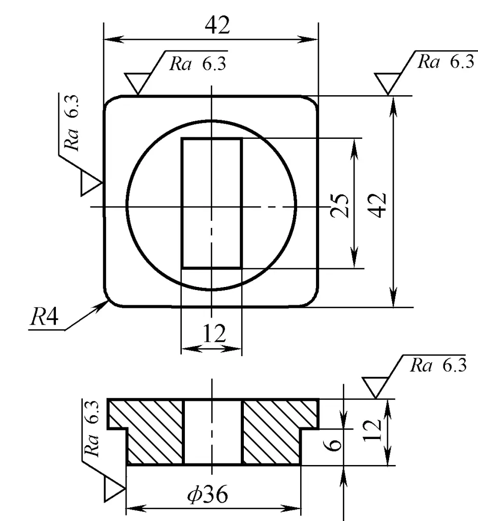
The shape and main dimensions of the flange forging are shown in Figure 2. The length of the part at the 36mm diameter is 11.5mm, which is 5.5mm longer than the corresponding part of the component, serving as a machining chuck during turning. This machining chuck is cut off afterwards, resulting in a through-hole component. Since the forging uses a top charging mechanism for demolding, the forging draft is minimal; only 30’.
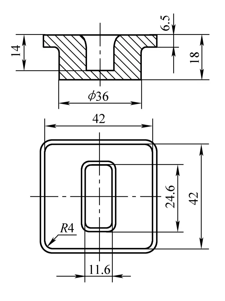
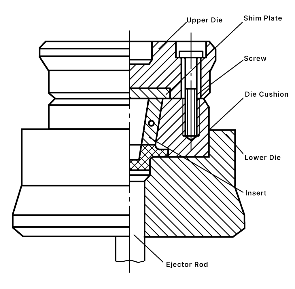
The forging die uses an insert structure (see Figure 3). The punch and lower die materials use 3Cr2W8V, with a heat treatment hardness of 43~48HRC. The surface roughness of the forging die groove is Ra1.60μm. The entire forging die is mounted on a die holder with a guiding device, and a small amount of lateral burr is produced during the final forming stage.
After switching to die forging for this part, each blank saves 0.115kg in weight compared to the original process. The blanks are heated in a box-type electric furnace, with a forging temperature range of 730 to 630°C. After die forging, cold trimming is performed, followed by annealing.