CO2 Laser Cutting Thickness, Speed & Power Chart (25-200W)
How can manufacturers achieve precise and efficient CO2 laser cutting for various materials? This article explores the relationship between laser…
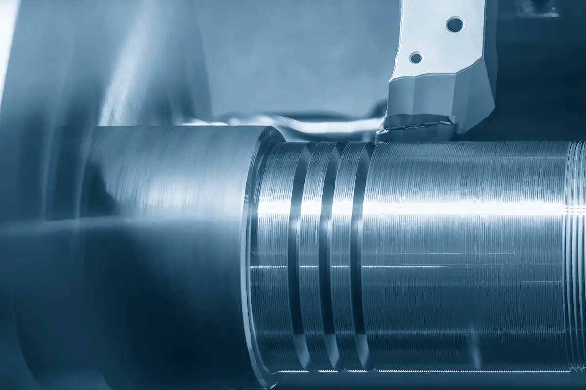
Are your cutting processes efficient enough? This article explores key strategies to enhance cutting efficiency, focusing on improving workpiece machinability, selecting appropriate cutting fluids, and optimizing tool geometric parameters. By understanding these essential techniques, you’ll be able to increase productivity, improve machining quality, and reduce costs. Dive in to learn how to transform your machining operations and achieve superior results.
Improving the machinability of workpiece materials, reasonably selecting cutting fluids, reasonably choosing tool geometry parameters and cutting amounts are important measures to improve machining quality, machining efficiency, and reduce machining costs.
The machinability of workpiece materials refers to the ease with which the workpiece material can be machined under certain cutting conditions. The purpose of studying machinability is to find ways to improve the machinability of materials.
The machinability of workpiece materials is related to the chemical composition, heat treatment state, metallographic structure, physical and mechanical properties, and cutting conditions of the material. Machinability can be measured by indicators such as tool life, cutting force, cutting temperature, and the roughness value of the machined surface.
When cutting ordinary metal materials, the machinability of the material is evaluated by the allowable cutting speed v60 when the tool life is 60 minutes; when cutting difficult-to-machine materials, the machinability of the material is evaluated by the v20 value.
The machinability of a certain material is relative to another material, so machinability is relative. When discussing the machinability of steel, the v 60 of 45 steel (170~229HBW, σb =637MPa) is generally used as the benchmark, denoted as v060 , and the ratio of v60 tov 060 of other materials is called relative machinability, i.e.,
Kr=v60/v060
When Kr >1, the material is easier to machine than 45 steel, and the machinability is good; when Kr <1, the material is more difficult to machine than 45 steel, and the machinability is poor. Table 2-5 shows the relative machinability and its classification.
Table 1 Relative machinability and its classification
| Machinability grade | Classification of workpiece materials | Relative machinability K | Representative materials | |
| 1 | Very easy to machine materials | General non-ferrous metals | >3.0 | Aluminum-magnesium alloy, ZnCuAll0Fe3 |
| 2 | Easy to machine materials | Free-cutting steel | 2.5~3.0 | Annealed 15Cr, automatic machine steel |
| 3 | Relatively easy to machine steel | 1.6~2.5 | Normalized 30 steel | |
| 4 | Ordinary materials | General steel, cast iron | 1.0~1.6 | #45 steel, gray cast iron, structural steel |
| 5 | Slightly difficult to machine materials | 0.65~1.0 | Quenched and tempered 2Cr13, 85 steel | |
| 6 | Difficult to machine materials | Relatively difficult to machine materials | 0.5~0.65 | Quenched and tempered 45Cr, quenched and tempered 65Mn |
| 7 | Difficult to machine materials | 0.15~0.5 | 1Cr18Ni9Ti, tempered 50CrV, some titanium alloys | |
| 8 | Very difficult-to-machine materials | <0.15 | Cast nickel-based superalloys, some titanium alloys | |
Easy-to-cut steel is a material that contains additives to improve machinability without reducing mechanical properties. When cutting this type of material, the tool life is long, cutting force is low, chips break easily, and the surface quality of the machined part is good.
High-carbon steel, tool steel, and other materials with high hardness can be annealed to reduce hardness, thereby improving machinability. Low-carbon steel can undergo processes such as normalizing and cold drawing to reduce plasticity and increase hardness, making cutting easier.
Medium-carbon steel can also be heat-treated by normalizing to achieve uniform microstructure and material hardness, thereby improving machinability.
Select tool materials that match the properties and requirements of the workpiece material.
Choose machining methods that are suitable for the properties and requirements of the workpiece material. With the development of cutting technology, new machining methods have emerged, such as heated cutting, low-temperature cutting, and vibration cutting, some of which can effectively machine difficult-to-machine materials.
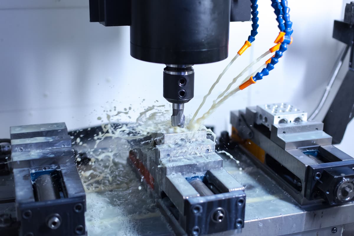
Proper use of cutting fluids can improve cutting conditions, reduce tool wear, and enhance the quality of the machined surface, making it an effective way to improve metal cutting efficiency.
When cutting fluid is poured into the cutting area, it reduces friction between the chips, tool, and workpiece through conduction, convection, and vaporization, thereby reducing heat generation. It also carries away the generated heat, lowering the cutting temperature and providing a cooling effect.
The lubrication function of cutting fluid is achieved by forming a lubricating oil film between the tool, chips, and workpiece surfaces.
The cleaning function of cutting fluid removes fine chips and abrasive particles adhering to the machine tool, cutting tool, and fixtures, preventing scratches on the machined surface and reducing tool wear.
The effectiveness of the cleaning function depends on the oiliness, fluidity, and pressure of the cutting fluid. Adding anti-rust additives to the cutting fluid can form a protective film on metal surfaces, preventing corrosion of the machine tool, cutting tool, and workpiece by the surrounding medium.
Water-soluble cutting fluids mainly include aqueous solutions, emulsions, and synthetic fluids.
1) Aqueous solutions
Aqueous solutions are cutting fluids with water as the main component and added anti-rust additives. Due to the high thermal conductivity, specific heat capacity, and heat of vaporization of water, aqueous solutions primarily provide a cooling function. Due to their poor lubrication performance, they are mainly used in rough machining and ordinary grinding processes.
2) Emulsions
Emulsions are cutting fluids made by diluting emulsified oil with 95% to 98% (by volume) water. Emulsified oil is formulated from mineral oil and emulsifiers. Emulsifiers enable the mineral oil to emulsify with water, forming a stable cutting fluid.
3) Chemical Synthetic Fluid
Chemical synthetic fluid is composed of water, various surfactants, and chemical additives. It has good cooling, lubrication, cleaning, and anti-rust properties. The synthetic fluid does not contain oil, which can save energy.
Oil-soluble cutting fluids mainly include cutting oil and extreme pressure cutting oil.
1) Cutting Oil
Cutting oil is a cutting fluid composed mainly of mineral oil with certain additives. The mineral oils used for cutting oil mainly include total loss system oil, light diesel oil, and kerosene. Cutting oil mainly serves a lubricating function.
2) Extreme Pressure Cutting Oil
After adding extreme pressure additives such as sulfur, chlorine, and phosphorus to the cutting oil, the lubrication effect and cooling function can be significantly improved, with sulfurized oil being the most widely used.
The commonly used solid lubricant is molybdenum disulfide, which forms a lubricating film with a very low friction coefficient, high temperature resistance, and high pressure resistance. It can be applied to the tool surface during cutting or added to the cutting fluid.
Cutting fluids should be reasonably selected based on the specific conditions such as workpiece material, tool material, processing method, and technical requirements.
High-speed tool steel tools have poor heat resistance and require the use of cutting fluids. During rough machining, cooling is the main focus, and it is also desirable to reduce cutting force and power consumption. A 3% to 5% emulsion can be used. During finish machining, the main goal is to improve the surface quality of the workpiece, reduce tool wear, and minimize built-up edge. A 15% to 20% (by volume) emulsion can be used.
Carbide tools have high heat resistance and generally do not require cutting fluids. If cutting fluids are to be used, they must be supplied continuously and sufficiently. Otherwise, the internal stress caused by sudden cooling and heating will lead to cracks in the tool.
Cutting cast iron generally does not require cutting fluids due to the formation of fragmented chips. When cutting copper alloys and non-ferrous metals, cutting fluids containing sulfur are generally not used to avoid corrosion of the workpiece surface. Cutting aluminum alloys generally does not require cutting fluids, but during reaming and threading, a mixture of kerosene and machine oil in a 5:1 volume ratio or light diesel oil is often added. If the requirements are not high, an emulsion can also be used.
The reasonable use of cutting fluids is very important. The location of pouring, the adequacy, and the method of pouring will directly affect the effectiveness of the cutting fluid.
The cutting deformation zone is the core area of heat generation, and the cutting fluid should be poured into this area as much as possible. The types and selection of cutting fluids are shown in Table 2.
Table 2 Types and Selection of Cutting Fluids
| No. | Name | Composition | Main Uses | |
| 1 | Aqueous Solution | A solution of sodium nitrate, sodium carbonate, etc., dissolved in water and diluted 100 to 200 times with water | Grinding | |
| 2 | Emulsion | (1) Very little mineral oil, mainly emulsified oil with surfactants, diluted 40 to 80 times with water, with good cooling and cleaning performance | Turning, Drilling | |
| (2) Emulsified oil mainly composed of mineral oil with a small amount of surfactant, diluted with 10-20 times water, has good cooling and lubrication performance. | Turning, threading | |||
| (3) Additives are added to the emulsion | High-speed turning, drilling | |||
| 3 | Cutting oil | (1) Mineral oil (L-AN15 or L-AN32 oil for total loss systems) used alone | Gear hobbing, gear shaping | |
| (2) Mineral oil mixed with vegetable oil or animal oil to form a mixed oil, with good lubrication performance | Precision thread turning | |||
| (3) Additives are added to mineral oil or mixed oil to form extreme pressure oil | High-speed gear hobbing, gear shaping, threading, etc. | |||
| 4 | Others | Liquid CO2 | Mainly used for cooling | |
| Molybdenum disulfide + stearic acid + paraffin made into a crayon, applied to the tool surface | Threading | |||
The tool is the direct tool for cutting processing. The rationality of its structure and geometric parameters plays a very important role in the quality and efficiency of cutting processing. Reasonable selection of tool geometric parameters can fully exert its cutting performance. There is an old Chinese saying, “To do a good job, one must first sharpen one’s tools,” which speaks to this principle.
The so-called reasonable geometric parameters of the tool refer to the geometric parameters that can ensure high productivity and low processing cost while guaranteeing processing quality.
The basic content of tool geometric parameters includes:
Tool geometric parameters are an organic whole, with interconnections and constraints among the parameters. The influence of each parameter on cutting performance during the cutting process has both beneficial and adverse aspects.
Therefore, when selecting tool geometric parameters, one should start from specific production conditions, focus on the main contradictions, i.e., the main parameters affecting cutting performance, and comprehensively consider and analyze the interrelationships among the parameters to fully exert the beneficial effects of each parameter and limit and overcome the adverse effects.
Increasing the rake angle can reduce cutting deformation and friction, lower cutting force and cutting temperature, reduce tool wear, improve processing quality, and inhibit built-up edge. However, an excessively large rake angle can weaken the cutting edge strength and heat dissipation capacity, making it prone to edge chipping. Therefore, the rake angle should not be too small or too large and should have a reasonable value, as shown in Figure 1 and Figure 2.
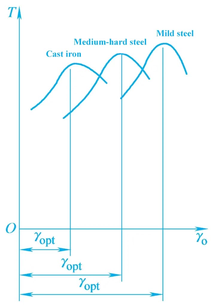
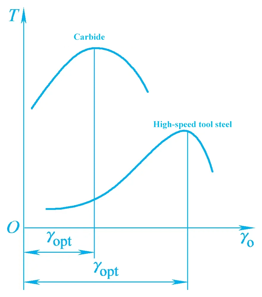
1) Select the rake angle based on the properties of the workpiece material
As shown in Figure 1, the greater the plasticity of the machining material, the larger the rake angle should be selected. This is because increasing the rake angle can reduce cutting deformation and lower cutting temperature.
When machining brittle materials, generally fragmented chips are obtained, cutting deformation is minimal, the contact area between the chip and the rake face is small, and the larger the rake angle, the weaker the cutting edge strength. To avoid edge chipping, a smaller rake angle should be selected. When the strength and hardness of the workpiece material are higher, to ensure sufficient strength and heat dissipation area of the cutting edge, and to prevent edge chipping and excessive tool wear, a smaller rake angle should be chosen.
2) Select the rake angle based on the properties of the tool material
As shown in Figure 2, when using tool materials with better strength and toughness (such as high-speed tool steel), a larger rake angle can be used; when using tool materials with poor strength and toughness (such as cemented carbide), a smaller rake angle should be used.
3) Select the rake angle based on the nature of the machining
During rough machining, the selected depth of cut and feed rate are relatively large. To reduce cutting deformation and improve tool life, a larger rake angle should be selected.
However, due to irregularities and hard surfaces of the blank, to enhance the strength of the cutting edge, a smaller rake angle should be selected; during finish machining, the selected depth of cut and feed rate are smaller, and the cutting force is smaller. To ensure a sharp cutting edge and guarantee machining quality, a larger rake angle can be selected. Table 3 provides reference values for reasonable rake angles of cemented carbide turning tools.
Table 3 Reference values for reasonable rake angles of cemented carbide turning tools
| Workpiece material | Reasonable rake angle | |
| Rough turning | Finish turning | |
| Low carbon steel | 20°~25° | 25°~30° |
| Medium carbon steel | 10°~15° | 15°~20° |
| Alloy steel | 10°~15° | 15°~20° |
| Quenched steel | -15°~-5° | |
| Stainless steel (Austenitic) | 15°~20° | 20°~25° |
| Gray cast iron | 10°~15° | 5°~10° |
| Copper and copper alloys | 10°~15° | 5°~10° |
| Aluminum and aluminum alloys | 30°~35° | 35°~40° |
| Titanium alloy Rm ≤1.177GPa | 5°~10° | |
1) Positive rake plane type
As shown in Figure 3a, the characteristics of the positive rake plane type are: simple manufacturing, can obtain a relatively sharp cutting edge, but low strength and poor heat transfer capability. It is generally used for finishing tools, forming tools, milling cutters, and tools for machining brittle materials.
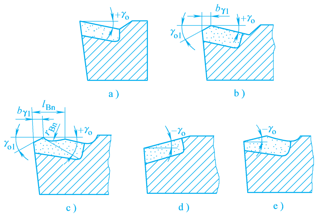
a) Positive rake plane type
b) Positive rake plane with chamfer type
c) Positive rake angle with chamfered surface
d) Negative rake angle single-sided type
e) Negative rake angle double-sided type
2) Positive rake angle with chamfered plane
As shown in Figure 3b, the chamfer is formed by grinding a very narrow edge at the cutting edge of the main cutting edge. The chamfer can improve the strength of the cutting edge and enhance the heat dissipation capability, thereby extending the tool life.
The width of the chamfer is very narrow. When cutting plastic materials, it can be selected according to br1 =(0.5~1.0)f, Yo1 =-5°~-15°. At this time, the chips still flow along the rake face and not along the chamfer. The chamfer form is generally used for rough cutting of castings and forgings or for machining interrupted surfaces.
3) Positive rake angle with chamfered curved surface
As shown in Figure 3c, this form is based on the positive rake angle with chamfered plane. To curl the chips and increase the rake angle, a certain curved surface is ground on the rake face. The parameters of the chip groove are approximately: lBn =(6~8)f, rBn =(0.7~0.8)lBn . It is commonly used for rough or finish machining of plastic materials.
4) Negative rake angle single-sided type
When wear mainly occurs on the flank face, a negative rake angle single-sided type as shown in Figure 3d can be made. At this time, the insert bears compressive stress and has good cutting edge strength. Therefore, it is often used for cutting high hardness (strength) materials and hardened steel materials, but the negative rake angle will increase the cutting force.
5) Negative rake angle double-sided type
As shown in Figure 3e, when wear occurs on both the rake and flank faces, a negative rake angle double-sided type can be made, which can increase the number of regrinds of the insert. At this time, the chamfered surface of the negative rake angle should have sufficient width to ensure that the chips flow along the chamfered surface.
Increasing the flank angle can reduce the friction between the flank face and the transition surface of the workpiece, reduce tool wear, and also reduce the radius of the cutting edge’s blunt circle, making the cutting edge sharp and easy to cut off chips, and can reduce the surface roughness value. However, an excessively large flank angle will reduce the strength and heat dissipation capability of the cutting edge.
The flank angle is mainly selected based on the cutting thickness. During rough machining, the feed rate is large, and the cutting thickness is large, so the flank angle should be small. During finish machining, the feed rate is small, and the cutting thickness is small, so the flank angle should be large. When the strength and hardness of the workpiece material are high, to improve the cutting edge strength, the flank angle should be small.
When the rigidity of the process system is poor and vibration is likely to occur, the flank angle should be appropriately reduced. For dimensioning tools (such as round hole broaches, reamers, etc.), a smaller flank angle should be selected to increase the number of regrinds and extend the tool life. Table 4 shows the reference values for reasonable flank angles of carbide turning tools.
Table 4 Reference values for reasonable flank angles of carbide turning tools
| Workpiece material | Reasonable flank angle | |
| Rough turning | Finish turning | |
| Low carbon steel | 8°~10° | 10°~12° |
| Medium carbon steel | 5°~7° | 6°~8° |
| Alloy steel | 5°~7° | 6°~8° |
| Quenched steel | 8°~10° | |
| Stainless steel (Austenitic) | 6°~8° | 8°~10° |
| Gray cast iron | 4°~6° | 6°~8° |
| Copper and copper alloys (brittle) | 6°~8° | 6°~8° |
| Aluminum and aluminum alloys | 8°~10° | 10°~12° |
| Titanium alloy Rm ≤1.177GPa | 10°~15° | |
The size of the secondary clearance angle is usually equal to the clearance angle. However, for some special tools, such as parting tools, to ensure tool strength, α₀’=1°~2° can be selected.
1) Double clearance angle
As shown in Figure 4a, to ensure the edge strength and reduce the workload of grinding the clearance face, a double clearance angle is often ground on the lathe tool’s clearance face.
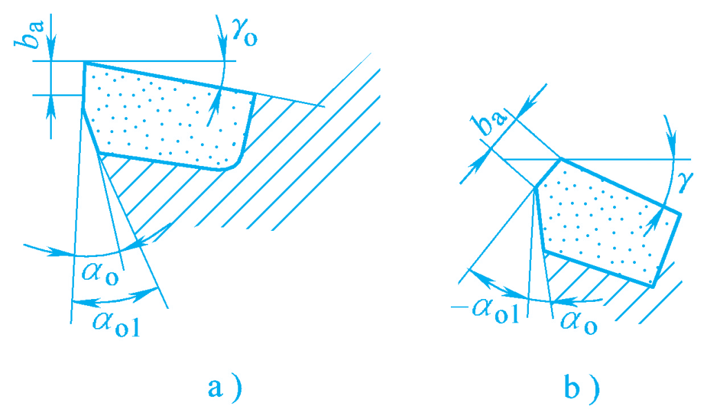
a) Edge band, double clearance angle
b) Vibration damping edge
2) Vibration damping edge
As shown in Figure 4b, to increase the contact area between the clearance face and the transition surface of the workpiece, increase damping, and eliminate vibration, a negative clearance angle edge can be ground on the clearance face, called a vibration damping edge.
3) Edge band
As shown in Figure 4a, for some dimensioning tools, such as broaches and reamers, to facilitate control of the outer diameter size and avoid rapid changes in size accuracy after regrinding, a small edge band with a zero-degree clearance angle is often ground on the clearance face. The edge band on the tool serves to stabilize, guide, and dampen the tool. The edge band should not be too wide, otherwise, it will increase friction.
The primary inclination angle Kr affects the size of the cutting force components. Increasing Kr will increase the Ff force and decrease the Fp force. The primary inclination angle affects the surface roughness of the machined surface; increasing the primary inclination angle increases the surface roughness. The primary inclination angle also affects tool life; when the primary inclination angle increases, tool life decreases.
The primary inclination angle also affects the shape of the workpiece surface. When turning stepped shafts, Kr =90° is selected. When turning slender shafts, Kr =75°~90° is selected. To increase versatility, Kr =45° can be selected for turning outer diameters, end faces, and chamfers.
Reducing the secondary inclination angle Kr ‘ will increase the contact length between the secondary cutting edge and the machined surface, reduce the surface roughness value, and improve tool life. However, too small a secondary inclination angle can cause vibration.
The principle for selecting the primary inclination angle is to choose a smaller primary inclination angle within the allowable rigidity of the process system, which is beneficial for improving tool life. In production, the primary inclination angle is mainly selected based on the rigidity of the process system, as shown in Table 5.
Table 5 Reference values for main cutting edge angle
| Working conditions | Main cutting edge angle Kr | |||||
| High system rigidity, small depth of cut, large feed rate, high workpiece material hardness | 10°~30° | |||||
| High system rigidity (l/d<6), machining disc parts | 30°~45° | |||||
| Medium system rigidity (l/d=6~12), large depth of cut or impact | 60°~75° | |||||
| Low system rigidity (l/d>12), turning stepped shafts, grooving, and cutting off | 90°~95° | |||||
Secondary cutting edge angle Kr ‘Mainly selected based on machining nature, generally Kr ‘ = 10°~15°, for finishing, choose the lower value. In special cases, such as cutoff tools, to ensure tool strength, Kr ‘ = 1°~2° can be selected.
1) Control the direction of chip flow
As shown in Figure 5, when λs = 0°, chips flow out perpendicular to the cutting edge; when λs is negative, chips flow towards the machined surface; when λs is positive, chips flow towards the unmachined surface.
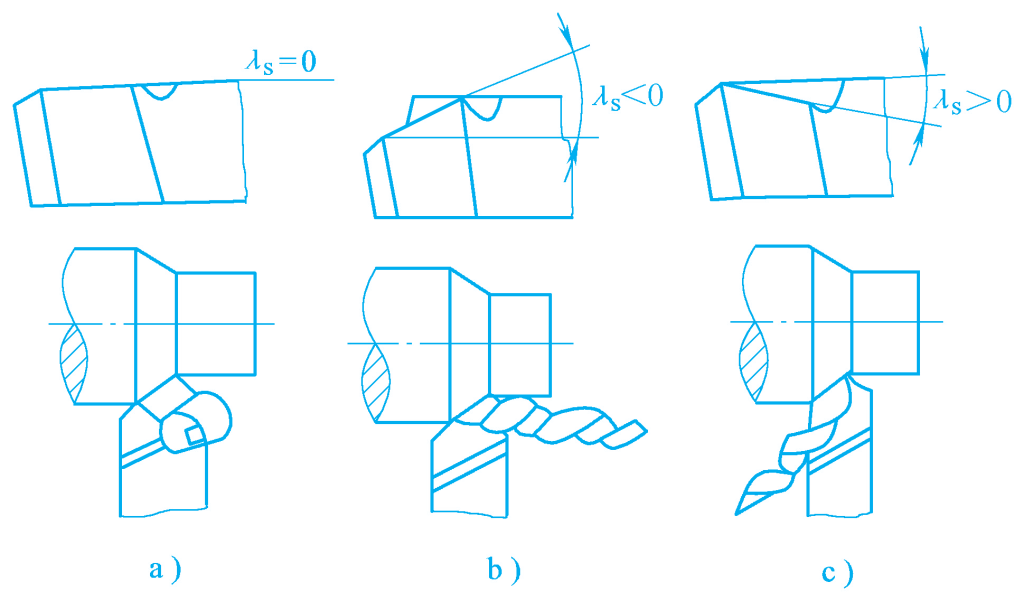
a)λs=0
b)λs<0
c)λs>0
2) Control the initial contact position of the cutting edge with the workpiece
As shown in Figure 6, when machining workpieces with interrupted surfaces, if the rake angle is negative, the lowest point of the cutting edge is the tool tip, and the first contact with the workpiece is a point on the cutting edge or the rake face, not the tool tip, thus the tool can withstand some impact load, protecting the tool tip; if the rake angle is positive, the first contact with the workpiece is the tool tip, which may cause chipping or tool breakage.
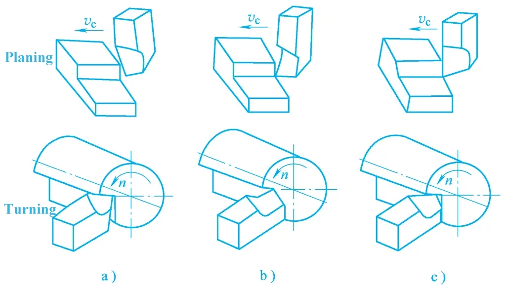
a)λs<0
b)λs>0
c)λs=0
3) Control the stability of the cutting edge when entering and exiting the workpiece
As shown in Figure 6, during interrupted cutting, when the rake angle is zero, the cutting edge contacts and leaves the workpiece simultaneously, causing significant vibration; if the rake angle is not zero, each point on the cutting edge gradually enters and exits the workpiece, resulting in a more stable cutting process.
4) Control the ratio of radial force to feed force
When the rake angle is positive, the radial force decreases, and the feed force increases; when the rake angle is negative, the radial force increases, and the feed force decreases.
When selecting the rake angle, specific analysis should be conducted according to the specific working conditions of the tool. Generally, it can be selected based on the machining nature. For finishing, λs = 0°~5°; for roughing, λs = 0°~-5°; for interrupted cutting, λs = -30°~-45°; for large rake angle finishing planing tools, λs = 75°~80°.
During the cutting process, the working conditions at the tool tip are very harsh, with issues such as low strength, poor heat dissipation, and easy wear. Therefore, improving the strength of the tool tip and increasing the heat transfer area at the tool tip is key to extending the overall tool life.
As shown in Figure 7a, the transition edge angle Krε ≈ Kr /2, length b ε ≈ (1/4~1/5) αp , this type of transition edge is mostly used on roughing or heavy-duty cutting tools.
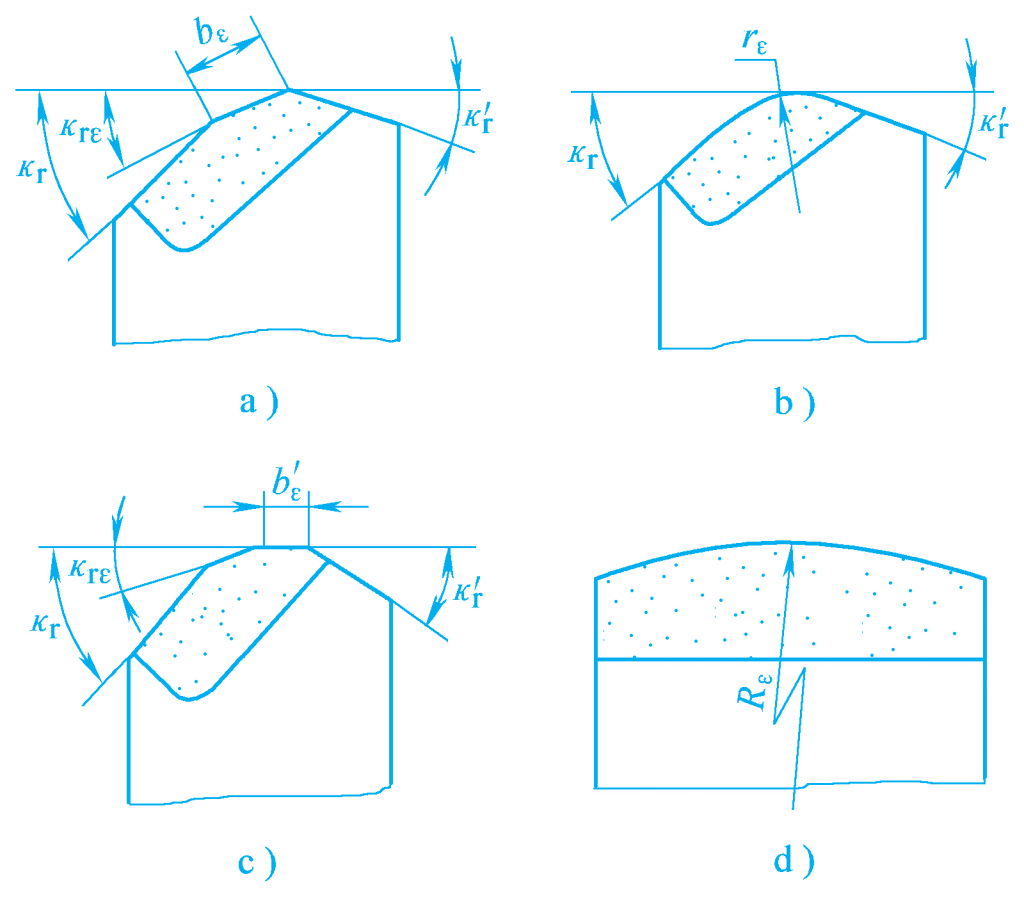
a) Straight edge
b) Arc edge (tool tip radius)
c) Parallel edge (horizontal finishing edge)
d) Large arc edge
As shown in Figure 7b, the transition edge can also be ground into an arc shape, and its parameter is the tool tip arc radius r ε .
When the tool tip arc radius increases, the average main cutting edge angle at the tool tip decreases, which can reduce the surface roughness value and improve tool life, but it will increase the back force and easily cause vibration, so the tool tip arc radius should not be too large. Typically, the high-speed steel turning tool rε = 0.5~5mm, and the carbide turning tool rε = 0.5~2mm.
As shown in Figure 7c, the finishing edge is a small parallel edge with Kr ‘= 0° ground near the tool tip on the secondary cutting edge. Its length b ≈ (1.2~1.5)f, that is, bε ‘ should be slightly larger than the feed rate f. However, if bε ‘ is too large, it can easily cause vibration.
As shown in Figure 7d, the large arc edge is a transition edge ground into a very large arc shape, and its function is equivalent to the horizontal finishing edge.
In metal cutting processing, studying the control of chip shape and chip flow direction is of great significance for maintaining normal production order and operator safety, especially on automatic machine tools and automatic production lines. The issues of chip breaking and chip curling should be given more attention, otherwise, it will affect normal production order.
1) Chip curling
Chip curling is caused by internal deformation of the chip, or by encountering chip breaking grooves, bosses, additional blocks ground on the tool’s rake face, or other obstacles.
2) Chip flow direction
The chip flow direction is mainly influenced by the cutting edge inclination angle. For details, see the previous section on the selection of the cutting edge inclination angle.
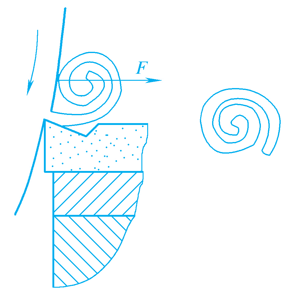
1) Chips encounter obstacles during the flow process and are broken by a bending moment.
As shown in Figure 8a, when the chip encounters the chip curling step, it is subjected to the force F, forming a bending moment, generating a large bending stress, and breaking in the chip curling groove. As shown in Figure 8b, if the bending stress does not reach the ultimate stress to break the chip, the chip will change direction and continue to move after bending deformation.
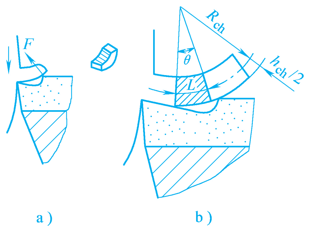
a) Chip broken by force F
b) Bending stress
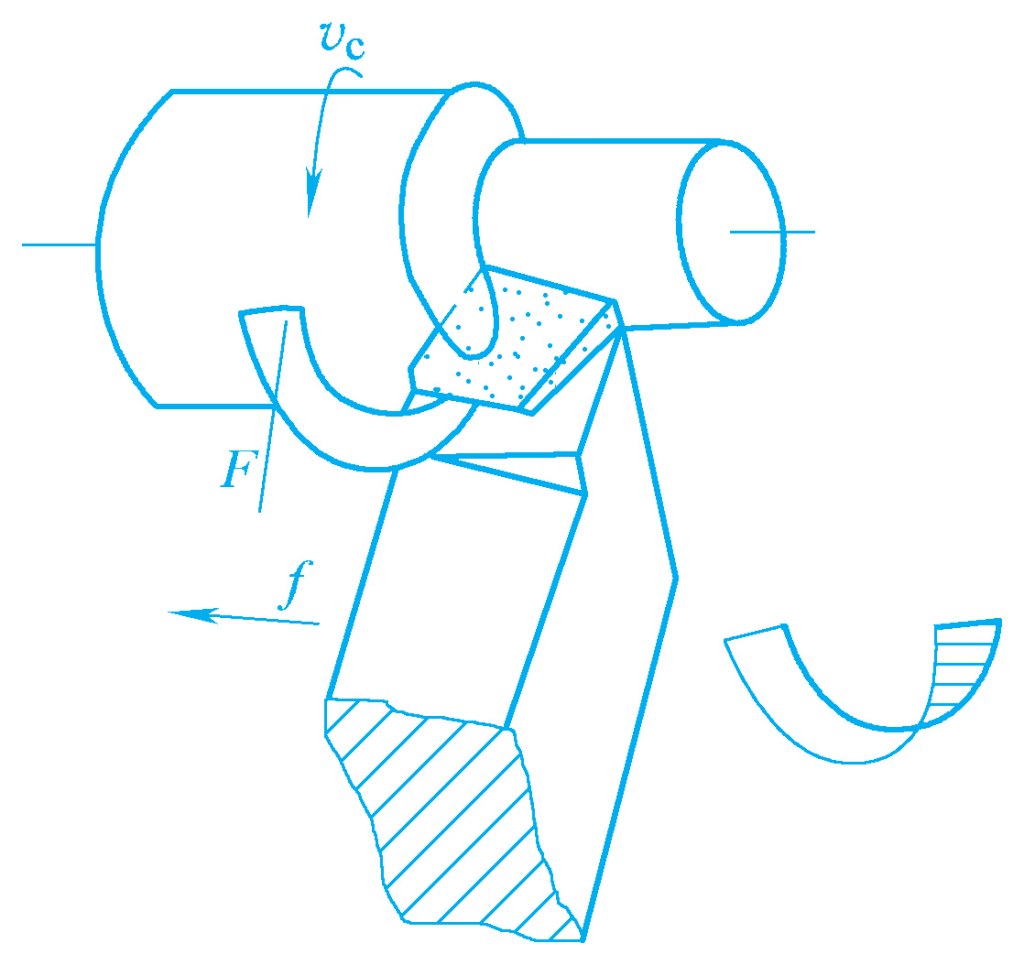
Figure 9 shows the chip encountering the workpiece’s surface to be machined during the curling movement, subjected to the reaction force forming a bending stress, and breaking into a “C” shaped chip; Figure 10 shows the chip forming a circular curled chip after encountering the workpiece’s transition surface; Figure 11 shows the chip breaking into a “C” shaped or “6” shaped chip after encountering the tool’s flank face.
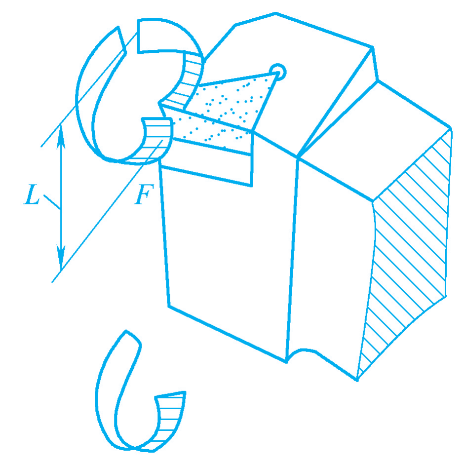
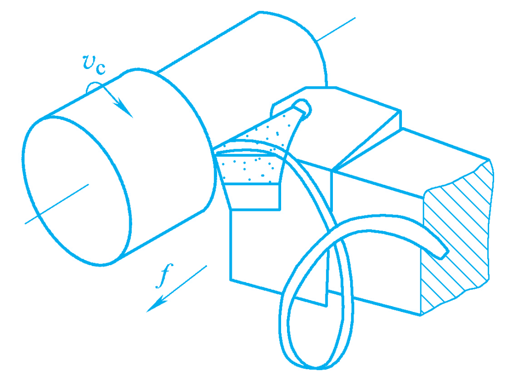
2) Chips are broken by their own weight during the flow process.
If the chip flows out from the rake face without encountering the tool or workpiece, it may form a long strip chip, or after forming a spiral chip in the chip curling groove, it breaks by its own weight, as shown in Figures 12 and 13.

Among the above chip types, “C” shaped chips, “6” shaped chips, and short spiral chips are generally considered ideal. Among them, the “C” shaped chips broken after encountering the tool’s flank face are stable and reliable, fall in a directed manner, and do not collide with the high-speed rotating workpiece, avoiding chip splashing. However, the cutting force has slight fluctuations, which is not conducive to reducing the surface roughness value of the workpiece.
The short helical chips that break off under their own weight are characterized by relatively stable cutting forces, which help reduce the surface roughness of the workpiece. However, they should not be too long (about 60~40mm), as this would hinder operation and chip removal.
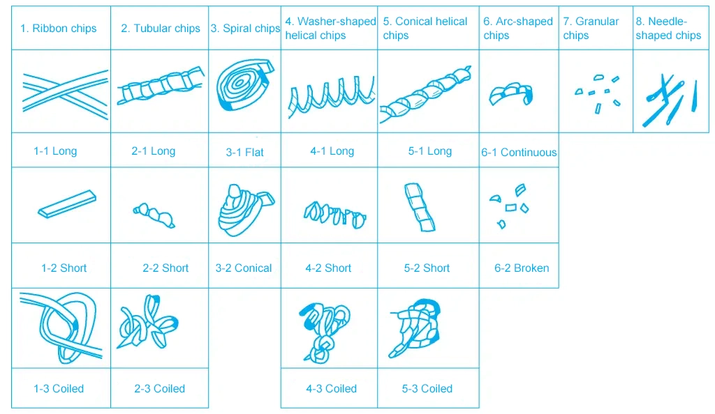
On automatic machine tools and automatic production lines, it is especially important to control the length of helical chips. Otherwise, chips wrapping around the workpiece or tool will affect normal production. During heavy-duty machining, due to the large depth of cut and feed rate, “C” shaped chips can easily cause injury, so it is preferable to generate spring-like chips. Various chip shapes produced during cutting are shown in Figure 14.
1) Chip groove (chip breaker groove)
The common cross-sectional shapes of chip grooves are broken line, straight line arc, and full arc, as shown in Figures 15a, 15b, and 15c. The smaller the width ln of the chip groove, the smaller the chip curl radius, the greater the bending stress, and the easier it is for the chip to break in the chip groove or after hitting the workpiece.
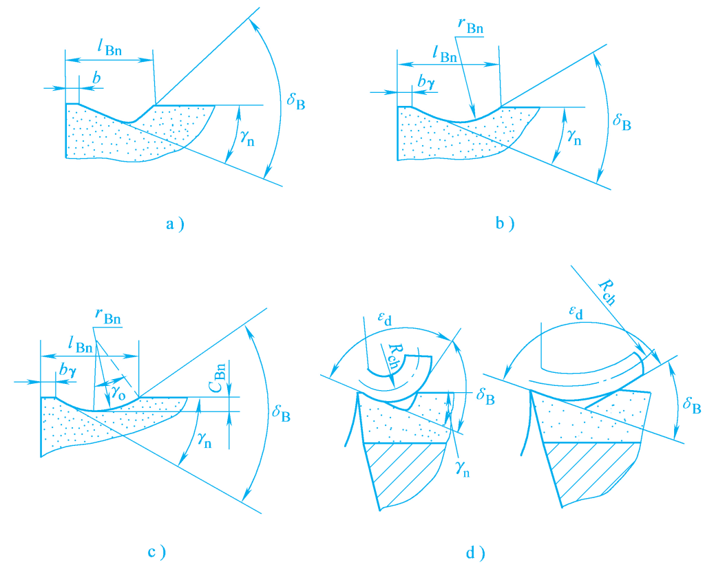
a) Broken line shape
b) Straight line arc shape
c) Full arc shape
d) Influence of chip angle δ B on R ch
However, it should not be too small, as the chip groove space for chips will be reduced, increasing cutting forces and leading to undesirable phenomena such as chip blockage, edge chipping, and chip splashing. Therefore, the width of the chip groove should be determined based on specific machining conditions, such as workpiece material and cutting parameters. Generally, the larger the feed rate, depth of cut, and main cutting edge angle, and the smaller the plasticity and toughness of the workpiece material, the larger the chip groove width should be, and vice versa.
In addition to the groove width, the chip angle δ B is also a major factor affecting chip breaking. As the chip angle increases, chips break more easily, but the chip curl radius R ch decreases, increasing curl deformation and bending stress, as shown in Figure 15d.
If the chip angle is too large, it can cause chip blockage, increasing cutting forces and cutting temperature. Additionally, the size of the chip groove arc radius r Bn also affects the chip breaking effect.
The chip groove inclination angle ρ Bλ is the angle between the side of the chip groove and the main cutting edge. It affects the chip flow direction and chip shape. Common chip groove inclination angles are external inclination, parallel, and internal inclination, as shown in Figure 16.
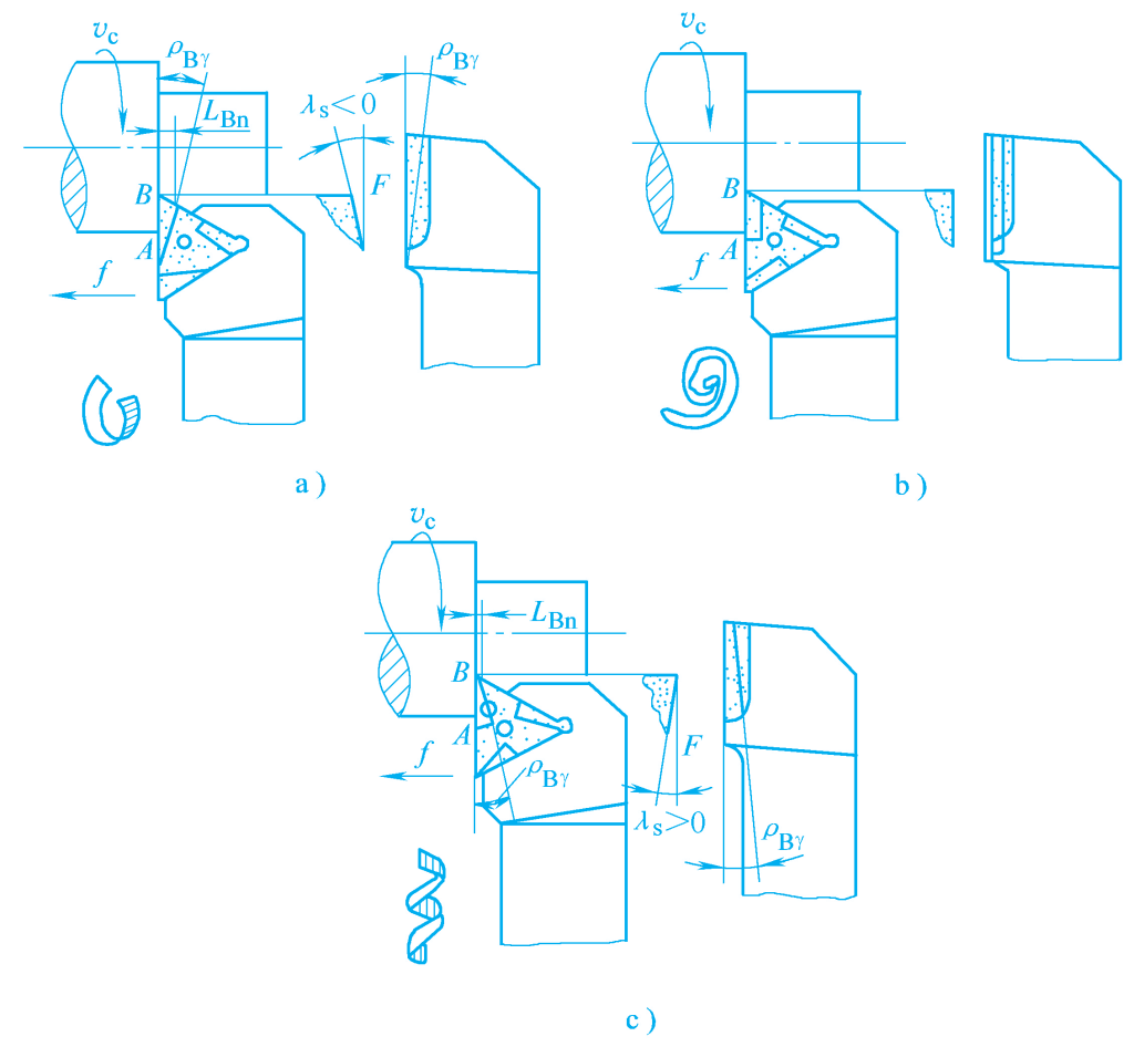
a) External inclination
b) Parallel
c) Internal inclination
The main feature of the external inclination is that the chip groove is wider at the front and narrower at the back in the width direction, and deeper at the front and shallower at the back in the depth direction. At point A of the groove, the cutting speed is high and the groove is narrow, causing the chip to curl first with a small radius. At point B of the groove, the chip curls more slowly. Due to the negative rake angle at the bottom of the groove, the chip flows towards the machined surface, forming “C” or “6” shaped chips after collision.
The external inclination has a wide chip breaking range and stable, reliable chip breaking. The internal inclination chip groove is narrower at point B and wider at point A. The chip at point B curls first with a small radius. The positive rake angle at the bottom of the groove causes the chip to flow away from the workpiece, forming tightly coiled helical chips that break off under their own weight after reaching a certain length.
It is mainly suitable for fine and semi-fine turning with small cutting parameters, but the chip breaking range is not large. The parallel chip groove has a chip breaking range and effect similar to the external inclination and is suitable when the depth of cut varies widely.
2) Tool geometry
Among the tool geometry angles, the main cutting edge angle and rake angle have a significant impact on chip breaking and chip flow direction. The larger the main cutting edge angle, the greater the cutting thickness, and thus the greater the bending force during chip curling, making chip breaking easier. Therefore, to achieve better chip breaking in production, a larger main cutting edge angle can be selected, such as K r = 75°~90°.
As mentioned earlier, the rake angle λ s is an important parameter for controlling chip flow direction. When the rake angle is negative, the chip flows towards the machined surface or transition surface, breaking into “C” or “6” shaped chips after colliding with the workpiece. When the rake angle is positive, the chip flows towards the unmachined surface or away from the workpiece, forming “C” shaped chips or possibly helical chips that break off.
3) Cutting parameters
Increasing the feed rate proportionally increases the cutting thickness, reduces the chip curl radius, increases bending stress, and makes the chip easier to break. Therefore, increasing the feed rate is a relatively effective measure for chip breaking.
4) Workpiece material
The greater the plasticity, toughness, and strength of the workpiece material, the more difficult it is to break the chips.
Chip control is a comprehensive issue involving controlling chip flow direction, curling, breaking, and chip shape. In production, the primary and secondary relationships should be comprehensively distinguished, and the impact of various factors on chip control should be considered.
The general rule is to determine the size parameters of the chip breaker groove based on the workpiece material and the selected tool angles and cutting parameters. Only when not restricted by other conditions, parameters such as the main deflection angle, rake angle, and feed rate are adjusted to achieve a more ideal chip control effect through trial cutting.
The so-called “reasonable” cutting parameters refer to the optimal combination of the three cutting elements that can fully utilize the efficiency of the tool and machine tool, ensuring high productivity and low processing costs while maintaining processing quality.
Although the three cutting elements v, f, and a have a direct impact on processing quality, tool life, and productivity, the degree of impact varies. They are interrelated and mutually restrictive, making it impossible to select all of them at their maximum values. Therefore, there is a need to prioritize which element should be maximized from different perspectives.
Generally, the depth of cut a is determined based on the nature of the machining and the machining allowance.
Cutting processes are generally divided into roughing (surface roughness value Ra50~12.5μm), semi-finishing (Ra6.3~3.2μm), and finishing (Ra1.6~0.8μm).
During roughing, if the machine tool rigidity allows, the roughing allowance should be removed in one pass as much as possible to reduce the number of passes, while retaining the allowance for semi-finishing and finishing. When using carbide tools on medium-power machine tools for external turning, the roughing depth of cut a is 2~6mm, the semi-finishing depth of cut a is 0.3~2mm, and the finishing depth of cut a is 0.1~0.3mm.
In the following cases, roughing should be done in multiple passes for the following reasons:
Even in the above cases, the depth of cut ap for the first or initial passes should be larger. If two passes are required, the first pass generally takes 2/3 to 3/4 of the machining allowance.
1) During roughing, where the surface quality requirements are not high, the selection of the feed rate f is mainly limited by the cutting force. If the rigidity of the tool holder, workpiece, and the strength of the insert and machine tool feed mechanism allow, a large feed rate should be selected.
2) During semi-finishing and finishing, since the depth of cut is relatively small and the cutting force generated is not large, the selection of the feed rate is mainly limited by the surface roughness requirements.
When the tool has a reasonable transition edge and finishing edge, and a higher cutting speed is used, the feed rate f can be appropriately increased to improve productivity. However, f should not be too small, as this would not only result in low productivity but also affect processing quality due to insufficient chip thickness. In production, the feed rate is often selected based on experience or by consulting tables.
Once the tool life T, depth of cut a, and feed rate f are determined, the cutting speed can be calculated using relevant formulas. In production, it is often determined based on experience or by consulting relevant cutting parameter manuals.
After determining the cutting speed, the spindle speed n can be calculated:
n=1000vc/(πdw)
In the formula:
The selected speed should be finally determined according to the machine tool manual (take the lower and similar machine tool speed n), and then the actual cutting speed should be calculated according to the selected speed.
When selecting the cutting speed, the following points should also be considered:
In actual production, the cutting parameters are mainly selected based on the process manual and the operator’s practical experience.