I. Marking Out
Drawing lines on the surface of a rough or machined workpiece to mark the boundaries for processing according to the drawing is called marking out.
After marking out the workpiece, there are clear indicators for processing. It clearly shows the machining allowance on the workpiece surface and helps locate holes or surfaces through the drawn lines. Through marking out, it’s possible to check in advance whether the dimensions of each part of the blank meet the requirements. For some blanks with small tolerances, marking out can also help find ways to salvage them, avoiding waste.
Marking out can also identify problems with the blank in advance, avoiding waste of manpower and resources. According to their function in processing, the lines drawn can be divided into three types: processing lines, verification lines, and alignment lines. Lines drawn on the surface of parts as processing boundaries according to drawing requirements are called processing lines.
Lines used to check for various errors after processing the parts, or even to analyze the reasons for defects, are called verification lines. Generally, the distance between verification lines and processing lines is 5-10mm depending on the size and shape of the part, but verification lines can be omitted when they might be confused with other lines. Lines drawn outside the processing lines are called alignment lines, used for aligning the part before processing.
The distance between alignment lines and processing lines is generally 3-10mm depending on the size of the part, but in special cases, it can be more than 10mm. In general situations, processing lines can also be used as alignment lines. The various lines drawn must be clear and accurate. To prevent important lines from being erased or becoming blurred after multiple transfers and processing, punch marks should be made on the lines.
Marking out can be divided into planar marking out and three-dimensional marking out. Planar marking out is done on one surface of the part, i.e., on a plane; three-dimensional marking out is done on several different planes of the part, i.e., marking out in three dimensions.
Marking tools include scribers, marking gauges, surface gauges, calipers, as well as hammers, center punches, etc. When using marking tools, note that: the needle tips used for marking are all hardened or tipped with hard alloy, and should not be bumped or struck; the height gauge is a more precise marking tool and should only be used for measurement, not for direct marking on the blank surface.
Center punches are made of tool steel and hardened by quenching, with their tip angles generally ground to 45°-60°. After marking, center punches are usually used to make small, uniform punch marks on the lines for easy observation. When drilling holes or drawing arcs, center punches are also used to mark the center, making it easy for the drill bit or compass point to align with the center.
Clamping and support tools include V-blocks, C-clamps, jacks, and various shims, used to clamp and support the workpiece.
1. Marking Out Datum
The datum used to determine the position of points, lines, and surfaces on the part drawing is called the design datum. The marking out datum refers to certain points, lines, and surfaces on the part used to determine dimensions, geometric shapes, and the relative positions of various elements on the workpiece during marking out. Other dimensional lines are measured starting from these points, lines, and surfaces.
Correctly selecting the marking out datum is essential for good line marking. A reasonable marking out datum can make marking convenient and accurate, while a poorly chosen datum can lead to failed marking. Therefore, it’s necessary to carefully analyze the drawing and processing technology to select the appropriate datum for the part before marking out.
The general principles for selecting a datum are: first, try to make the marking out datum consistent with the design datum; second, consider the shape of the blank, preferably using holes in the blank or large flat surfaces as the marking out datum.
The following three types of datum selection are commonly used:
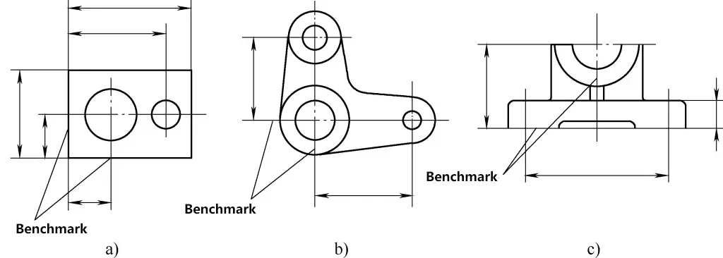
(1) Using two perpendicular planes as datum
As shown in Figure 1a, most dimensions in each direction are marked based on these two surfaces (the design datum on the drawing). In this case, these two surfaces can be used as the marking out datum.
(2) Using two center lines as datum
As shown in Figure 1b, most dimensions on this part are marked from these two center lines, and the dimensions in both directions are symmetrical to their respective center lines. Therefore, these two center lines can be used as the marking out datum.
(3) Using one plane and one center line as datum
As shown in Figure 1c, the vertical dimensions of this part are determined based on the bottom line, while the horizontal dimensions are symmetrical to the center line.
2. Alignment and Material Utilization in Marking Out
(1) Alignment
Due to technological reasons, the cast, forged, and welded blanks to be processed have certain errors and defects in dimensions and shape. If the errors are large, it may cause the workpiece to be scrapped. Therefore, alignment should be performed on the blanks before marking, and alignment should be carried out after determining the marking reference.
The following principles should be followed during alignment:
1) When there are unprocessed surfaces on the blank workpiece, align according to the unprocessed surface before marking. This will maintain consistent thickness between the unprocessed surface and the surface to be processed.
Figure 2 shows a bearing housing blank. The outer circle and surface A do not need processing. When marking the processing line for the inner hole, first align based on the outer circle, insert a filler (lead block or adjustable centering tool) into the hole, use a marking gauge to find the center, and mark the processing line for the inner hole according to the center.
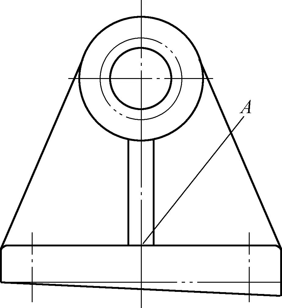
This way, the inner hole and outer circle can basically achieve concentricity. Similarly, before marking the processing line for the bottom surface, first align based on the upper plane A (unprocessed surface) and mark the processing line for the bottom surface. This ensures relatively uniform thickness throughout the base.
2) When all surfaces of the blank are to be processed, align the position of each surface to be processed before marking. This allows for a reasonable and uniform distribution of machining allowance on each surface to be processed, avoiding uneven or skewed allowance.
Due to the various structural shapes of parts, alignment work should be carried out according to the actual situation of the workpiece. When there are two or more unprocessed surfaces on the workpiece, choose the larger, more important, or higher appearance quality surface as the main alignment reference, while considering other less important unprocessed surfaces. This is to ensure that the dimensions between the main unprocessed surfaces and the surfaces to be processed (such as the wall thickness of the housing, the height of protrusions, etc.) are as uniform as possible, and to reflect difficult-to-compensate errors on secondary or less obvious areas.
When there are already processed surfaces on the part, the processed surface should be used as the alignment reference.
(2) Material Borrowing
When errors and defects in the shape, size, and position of the blank part cannot be remedied after alignment, consider using the method of material borrowing to remedy the situation.
When the non-conforming blank has a small tolerance deviation, through trial marking and adjustment, redistribute the machining allowance of each surface to be processed on the blank, minimizing the impact of the original error and turning it into a qualified product. This remedial method is called material borrowing.
When borrowing material, first check the dimensions and offsets of various parts of the blank to determine the direction and size of material borrowing, and mark the reference lines. Then, trial mark the remaining lines until appropriate.
Figure 3 shows a gear box housing where a casting error has caused hole A to shift 6mm to the right, changing the center distance from the designed 200mm to 194mm. Conventionally, if both holes were aligned based on their respective unprocessed outer circles of the protrusions, the right side of hole A would have no machining allowance, causing scrap.
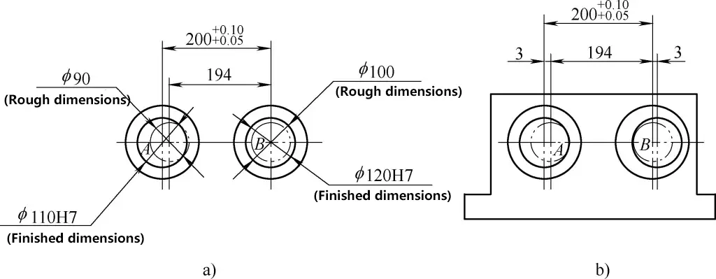
Now, using the material borrowing method, shift holes A and B 3mm to the left and right respectively. Trial mark the center lines of both holes and the inner hole circumference dimension lines. This way, both holes have appropriate machining allowance. This approach distributes the casting error evenly to the outer circles of the protrusions of both holes, causing a slight eccentricity between the outer circle protrusions and the inner holes (see Figure 3b). However, the degree of eccentricity is not significant and generally has little impact on the appearance quality, usually meeting the requirements of the part.
(3) Marking Steps
1) Carefully analyze the drawing, clarify the function and requirements of the part and its relevant marking areas in the machine. Some more complex parts require multiple markings and processing to complete. Therefore, before marking, familiarize yourself with the entire process of the part and mark the lines for this process as required. When marking, avoid marking lines that will be removed during processing and marking unnecessary lines.
2) Select the marking reference.
3) Clean and inspect the workpiece. Remove risers, flash, sand, oil, etc.
4) Apply color to the workpiece. For cast and forged blanks, white lime slurry (made by mixing white lime, water glue or peach gum with water) is commonly used for coloring. When the surface roughness of the workpiece is high and the quantity is very small, white chalk can also be used for coloring the workpiece.
Processed surfaces are often colored with light gold water (a mixture of shellac varnish and alcohol solution) with added colorant (basic dye). Regardless of the type of coating used, it should be applied thinly and evenly to ensure clear marking. If applied too thickly, it may peel off.
5) Mark the lines.
6) Carefully check if the marked lines are correct and if any lines are missing.
7) Punch marks on the lines. When using a center punch, the tip should be aligned with the center of the line or hole, and the hammer force should be appropriate and uniform. The punch marks should be on the center of the lines and holes, not skewed. The distance between punch marks and their size should be determined based on the size of the workpiece, the length of the lines, and the size of the holes, ensuring they are clearly visible for processing.
Generally, the punch marks on processing lines should not be too large or deep. The density of punch marks should follow the principle of “sparse on straight lines, dense on curves, and definite at intersection points”. For rough blanks and hole centers, larger and deeper punch marks are better, as they help in centering when drilling. For thin plates or thin workpieces, do not use too much force to prevent deformation. Punch marks are prohibited on softer materials and finely processed surfaces.
(4) Marking with the Aid of a Dividing Head
1) Structure of the Dividing Head
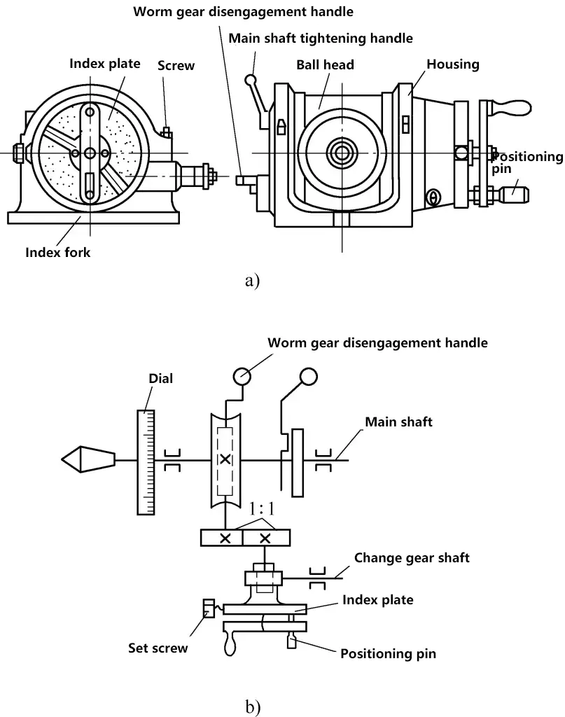
The dividing head is a tool for dividing the circumference equally, and it is often used in marking. Figure 4a shows the external form of a universal dividing head. The universal dividing head mainly consists of a shell, spindle, drum-shaped rotating body, dividing plate, and dividing fork.
a) External form
b) Drive system
The front end of the spindle has an internal taper hole and external threads, which can be used to insert a center and mount a self-centering chuck. The dividing plate is also fixed on the spindle and rotates with it, with 0° to 360° graduations used for division.
The spherical head of the spindle can rotate within the annular guide rail of the shell, allowing it to tilt upwards 90° and downwards 10° relative to the worktable surface, rotating at any angle within this range. Once the appropriate angle is selected, it can be fixed with screws on the shell for convenient marking.
The drive system of the dividing head is shown in Figure 4b. One end of the dividing head handle is installed in the sleeve at the center of the dividing plate, while the other end’s gear meshes with the gear on the worm shaft.
For simple division, use the fixing screw to secure the dividing plate, turn the handle, and through gear transmission, the worm drives the worm wheel to rotate for division. The change gear shaft behind the dividing plate is for complex division, where change gears for division can be installed.
2) Division Principle and Calculation
The dividing head can be used to divide the circumference equally or mark angle lines. Install the workpiece on the front end of the dividing head spindle, place the dividing head on the marking platform, and use it in conjunction with a scribing block to mark horizontal lines, vertical lines, and various angle lines.
Set the number of worm wheel teeth on the dividing head to 40, with a single-start worm. When the handle turns one revolution, the dividing head rotates 1/40 of a revolution. If the workpiece mounted on the spindle needs to be divided into z equal parts, i.e., drawing a line every 1/z revolution, the number of turns of the handle can be calculated according to the transmission relationship formula. That is
1/40=1/(zn)
n = 40/z
Where
- n – number of turns of the dividing head handle;
- z – number of equal divisions of the workpiece.
Example 1 Divide a circumference into eight equal parts using a dividing head.
Solution Given z=8, n=40/z=40/8=5, meaning the handle turns 5 revolutions to draw a line on the circumference.
Example 2 Divide a circumference into six equal parts using a dividing head.
Solution Given z=6, n=40/z=40/6=63, meaning the handle turns (6+2/3) revolutions for the workpiece to rotate 1/6 of a revolution.
As seen in Example 2, in production, it’s common to encounter situations where the handle needs to turn a non-integer number of revolutions. In such cases, use the following formula to calculate. That is
40/z=a+P/Q
Where
- a – the integer number of revolutions of the dividing handle;
- Q – the number of holes in a certain circle on the dividing plate;
- P – the number of holes the handle should turn on the circle with Q holes.
3) Selection of dividing plates
Dividing plates are used for division counting. There are several circles of very accurate small holes with different numbers on the dividing plate. When the calculated n value after division has a fraction, this fraction’s numerator and denominator should be expanded (or reduced) by the same factor to make the denominator equal to the number of holes in a certain circle on the dividing plate. The resulting numerator value is then the number of hole spacings the handle should turn.
As in Example 2 above, after the handle turns 6 revolutions, it still needs to turn 2/3 of a revolution. Referring to Table 1, the denominator and numerator can both be multiplied by 8, expanding 2/3 to 16/24, meaning turning 16 hole spacings on the circle with 24 holes.
Of course, 2/3 can also be expanded to 44/66, meaning turning 44 holes on the 66-hole circle, which similarly results in the main shaft rotating 2/3 of a revolution. It can be expanded to many other multiples, but since circles with more holes are farther from the axis center, it’s more convenient to turn the handle, so they are often used. The universal dividing head usually comes with more than one dividing plate, and the number of holes on various dividing plates can be seen in Table 1.
Table 1 Number of holes on dividing plates
| Number of plates included | Number of holes on dividing plates |
| 1 plate | Front: 24, 25, 28, 30, 34, 37, 38, 39, 41, 42, 43 Back: 46, 47, 49, 51, 53, 54, 57, 58, 59, 62, 66 |
| 2 plates | Front of the 1st plate: 24, 25, 28, 30, 34, 37 Back: 38, 39, 41, 42, 43 Front of the 2nd plate: 46, 47, 49, 51, 53, 54 Back: 57, 58, 59, 62, 66 |
| 3 plates | Block 1: 15, 16, 17, 18, 19, 20 Block 2: 21, 23, 27, 29, 31, 33 Block 3: 37, 39, 41, 43, 47, 49 |
The dividing fork can make division accurate and quick. The dividing fork should be adjusted before turning the handle. The angle between the two fork legs can be adjusted according to the number of hole spacings.
When adjusting, the number of holes between the angles should be one more than the required number of hole spacings, because the first hole is counted as zero, and only the second hole counts as one hole spacing. After each division rotation of the handle, the dividing fork should be turned to the new positioning position (the starting position of the second division) in the direction of the handle rotation.
When using the dividing head, the spindle locking handle must be loosened before each division. During division, the dividing handle must be turned in one direction to ensure accurate division. When the dividing handle is about to turn to the predetermined hole position, be careful not to let it turn too far; the positioning pin should just fit into the hole.
If you find that it has gone too far, you must turn it back about half a turn and then turn it to the predetermined hole position again. When dividing and drawing lines, tighten the spindle to prevent it from loosening during the line drawing process.
II. Sawing
The machining method of cutting or slotting raw materials or workpieces using a saw is called sawing.
The saw blade is the cutting part. Hand-held saw blades are generally 300mm long, usually made of carbon tool steel or alloy steel, and hardened by heat treatment. Hand saws cut during forward pushing, so the saw blade must be installed with the teeth facing forward. If the saw blade is installed backwards, it not only cannot cut normally but also accelerates tooth wear. The installation method of the saw blade is shown in Figure 5.

a) Correct
b) Incorrect
The coarseness of the saw teeth is expressed by the number of teeth per 25mm length of the saw blade, with options of 14, 18, 24, and 32. Coarse-toothed saw blades have larger chip grooves and are suitable for sawing soft materials and larger cross-sections; fine-toothed saw blades are suitable for sawing hard materials, thin plates, or pipes. The specifications and applications of saw blade coarseness are shown in Table 2.
Table 2 Specifications and applications of saw blade coarseness
| Saw tooth coarseness | Number of teeth per 25mm length | Application |
| Coarse | 14~18 | Sawing soft steel, brass, aluminum, cast iron, pure copper, and artificial resin materials |
| Medium | 22~24 | Sawing medium-hardness steel, thick-walled steel pipes, copper pipes |
| Fine | 32 | Thin pure metals, thin-walled pipes |
| Fine to Medium | 32~20 | Generally used in factories for starting cuts |
The tightness of the saw blade should be moderate, and can be adjusted using the butterfly nut on the saw frame. If too tight, the saw blade will be under high stress and lose its necessary elasticity, making it prone to breakage; if too loose, the saw blade can easily bend and break, and the saw cut may become skewed. The installed saw blade should be kept in the same middle plane as the saw frame, which is necessary to ensure a straight saw cut and prevent the saw blade from breaking.
There are two types of saw frame movement when pushing the saw: one is linear motion, suitable for slots with flat bottom surfaces or thin-walled workpieces; the other allows the saw frame to swing up and down, which can reduce cutting resistance, improve work efficiency, and is more natural to operate, reducing hand fatigue.
When the sawing speed is too fast, the material being sawed is too hard, or appropriate cutting fluid is not used, it can cause the tooth part to overheat, rapidly wear the tooth sides, increase friction between the saw blade and the saw cut, leading to further accelerated wear of the saw teeth.
When starting to saw, if the starting angle is too large, the saw teeth hook onto the workpiece’s sharp edge, or if the chosen saw blade’s tooth coarseness is inappropriate, or if the pushing angle suddenly changes during sawing, or if hard impurities are suddenly encountered in the material being sawed, it can all lead to tooth breakage; if the saw blade is installed too loose or too tight, the workpiece is not firmly clamped, the sawing is unstable and produces vibrations, or if corrections to a skewed saw cut are made too abruptly, it can all result in saw blade breakage.
When sawing pipes and thin plates, fine-toothed saw blades must be used. Otherwise, if the tooth pitch is larger than the plate thickness, it will cause the saw teeth to hook and result in tooth loss or breakage. Therefore, during sawing, at least two or more saw teeth should be cutting simultaneously on the cross-section to avoid the phenomenon of saw teeth getting hooked and causing breakage.
When sawing, depending on the shape and thickness of the material, sawing methods can be divided into the following types.
1. Sawing of bar stock
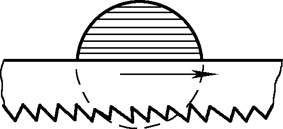
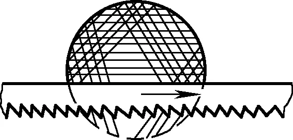
If a smooth cross-section is required for sawing, it should be sawed continuously from start to finish (see Figure 6); if the requirements for the sawed cross-section are not high, it can be sawed in several directions (see Figure 7), which makes it easier to saw due to the smaller sawing surface, thereby improving work efficiency.
2. Sawing of pipes
Before sawing a pipe, draw a sawing line perpendicular to the axis. Since the requirements for the sawing line are not high, the simplest method is to wrap a rectangular paper strip (with a straight edge for marking) around the outer circumference of the workpiece according to the sawing dimensions, and then mark it with a scriber. When sawing, the pipe must be clamped correctly. For thin pipes and precision-machined pipes, they should be clamped between two wooden pads with V-shaped grooves to prevent the pipe from being flattened or damaging the surface.
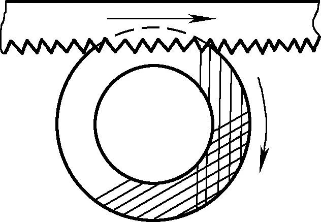
When sawing thin-walled pipes, do not saw continuously in one direction from start to finish. Otherwise, the saw teeth will be hooked by the pipe wall and cause chipping. The correct method is to first saw in one direction to the inner wall of the pipe; then rotate the pipe at a certain angle in the direction of the saw push, connect to the original saw kerf and saw to the inner wall of the pipe again. Gradually change direction and continue rotating and sawing until it is cut through, as shown in Figure 8.
3. Sawing of thin materials
When sawing relatively thin sheet materials, bending and vibration may occur during sawing, making it impossible to proceed. When sawing, try to saw down from the wide surface as much as possible. When it’s only possible to saw down from the narrow surface of the sheet, two wooden boards can be used to clamp it and saw through together with the wooden boards. This is to avoid the saw teeth from hooking and also increase the rigidity of the thin sheet, preventing vibration during sawing, as shown in Figure 9a.
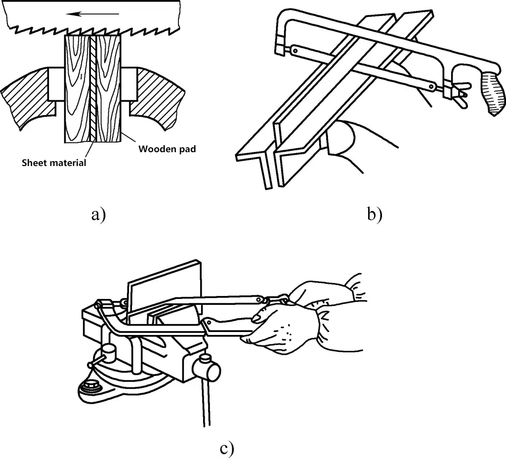
If sawing a longer sheet material, two angle irons can be used as backing plates for the vise jaws, clamping the sheet material tightly, and then sawing along the angle iron, as shown in Figure 9b. Alternatively, the thin sheet material can be clamped on a bench vise and sawed horizontally with a hand saw, increasing the number of teeth in contact with the thin sheet to avoid chipping of the saw teeth, as shown in Figure 9c.
4. Deep groove sawing
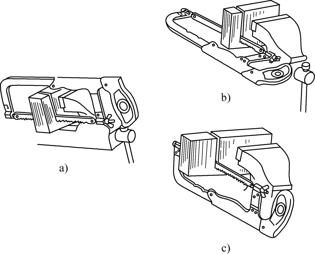
When the depth of the saw kerf exceeds the width of the saw frame, the saw blade should be rotated 90° and reinstalled, turning the saw frame to the side of the workpiece. When the height of the saw frame is still not enough with the frame turned sideways, the saw blade can also be installed with the teeth facing the saw (rotating the blade 180° within the frame) for sawing, as shown in Figure 10.
III. Chiseling
Chiseling is a method of processing workpieces by striking a chisel with a hammer. This operation is called chiseling. Chiseling is mainly used in situations where mechanical processing is inconvenient, including removing burrs from castings, cutting sheet materials, removing waste rivets and rusted screws, chiseling off misaligned protrusions on mating parts, cutting oil grooves, etc. Sometimes it is also used for rough machining of relatively small areas.
1. Chisels
The quality of the chisel directly affects the quality and efficiency of chiseling. The main factors affecting chisel quality are the rational shape and hardness of the cutting edge.
(1) Wedge angle β
The shape of the cutting edge (cutting part) is represented by the wedge angle β, which is the angle between the front face and the back face of the cutting edge. The larger the wedge angle, the higher the strength of the chisel edge, but the cutting resistance is also greater; the smaller the wedge angle, the sharper the chisel edge. Therefore, when choosing the wedge angle, the smallest possible value should be taken while ensuring sufficient strength. When chiseling hard materials, the wedge angle should be larger, and when chiseling soft materials, the wedge angle should be smaller.
When chiseling hard materials such as steel or cast iron, the wedge angle is typically 60° to 70°; for materials of medium hardness, the wedge angle is 50° to 60°; for soft materials like copper or aluminum, the wedge angle is 30° to 50°.
(2) Back angle α
The angle between the back face of the chisel and the cutting plane is called the back angle. The size of the back angle is determined by the position in which the chisel is held. The purpose of the back angle is to reduce friction between the back face and the cutting surface, and to make it easier for the chisel to penetrate the material. The back angle is generally determined by experience, usually 5° to 8°. If it’s too small, it may slip; if it’s too large, it may cut too deep, as shown in Figure 11.

The hardness of the chisel edge should be higher than that of the workpiece being cut. The harder, sharper, and less prone to curling the chisel edge is, the better. However, if the hardness is too high, it can cause the chisel edge to become brittle and chip easily, or even cause fragments to fly off and injure someone. Therefore, the hardness of the chisel must be appropriate.
Chisels are generally forged from T7A tool steel and subjected to heat treatment. The heat treatment of chisels includes quenching and tempering processes. Chisels quenched to a “yellow heat” have higher hardness but lower toughness; those quenched to a “blue heat” have lower hardness but higher toughness. Generally, a hardness between these two is used – quenched to a “golden yellow heat”.
The specific method is as follows: Heat the cutting part of the chisel, about 20mm in length, in a heating furnace to 750-800°C (cherry red color), then quickly remove it and place the chisel vertically into cold water to cool (immersion depth of 5-6mm) to complete the quenching process.
When cooling the chisel in water, it should be gently swayed along the water surface. This is done to accelerate cooling, increase quenching hardness, prevent a clear boundary between the hardened and non-hardened parts to avoid chisel breakage at this line, remove air bubbles adhering to the chisel surface, and prevent soft spots from forming during quenching. After quenching, the chisel also needs to be tempered, which is done using its own residual heat.
When the part of the quenched chisel above the water surface turns black, remove it from the water, wipe off the oxide scale, and observe the color change of the chisel edge. For general wide chisels, when the edge part turns purple (between purplish red and dark blue), and for general narrow chisels, when the edge part turns brownish red (between yellowish brown and red), immerse the chisel in water again to cool. This completes the entire quenching-tempering process of the chisel.
The timing of fully immersing the chisel in cold water greatly affects the hardness of the cutting edge. If it’s too early, the edge becomes too brittle; if it’s too late, the edge becomes too soft. Only through continuous practice can one skillfully achieve the ideal chisel hardness. In winter, warm water should be used for quenching, otherwise, the cutting edge may easily break.
When sharpening the chisel, ensure that the front and back faces are smooth and flat, the wedge angle is correct and sharp. If necessary, after grinding on a wheel, it should be finely ground on a whetstone. During grinding, it’s important to continuously cool with water to prevent annealing due to high temperatures.
There are several types of chisels, including flat chisels, point chisels, and oil groove chisels, as shown in Figure 12.
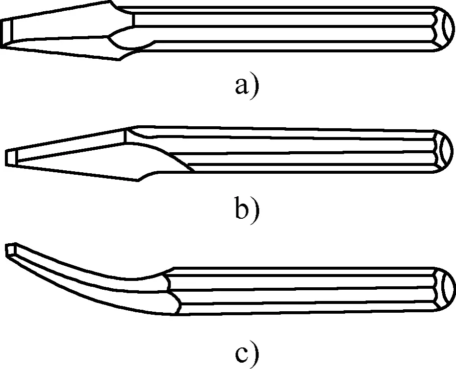
a) Flat chisel
b) Point chisel
c) Oil groove chisel
2. Chiseling methods
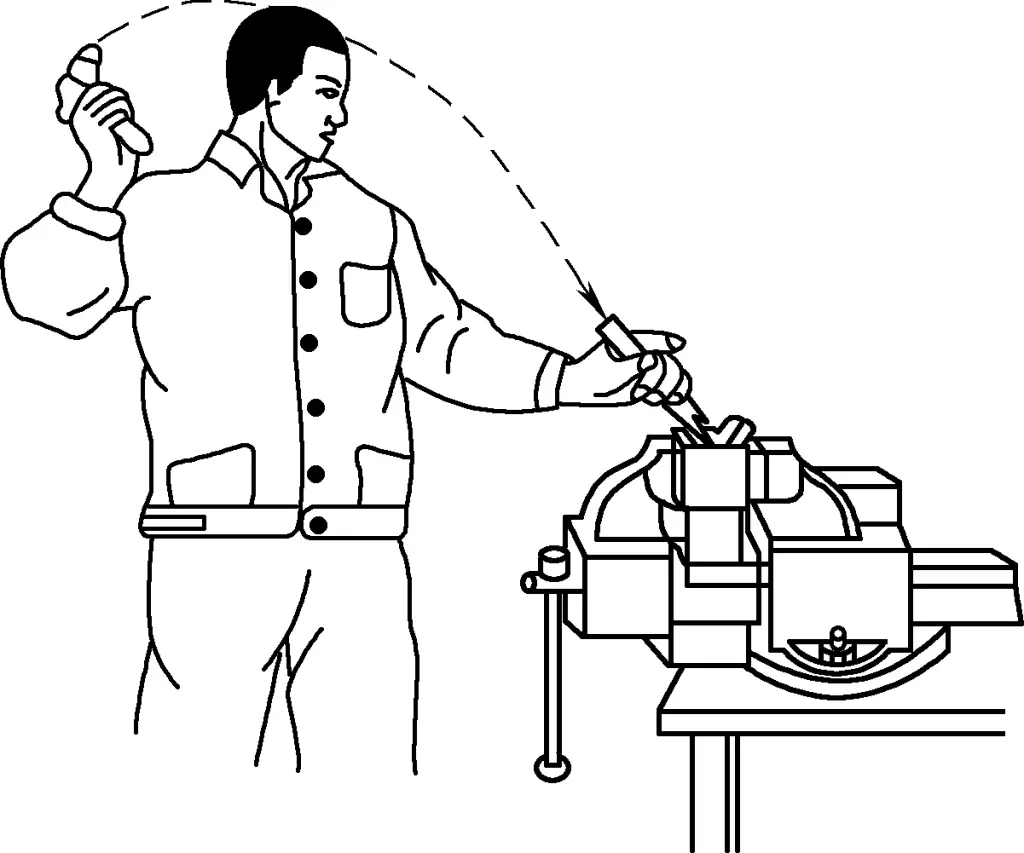
When chiseling, the eyes should focus on the chisel edge. Beginners often watch the hammer or chisel handle, which is incorrect. When swinging the hammer, the arm should be relaxed, and one should learn to use wrist power. The angle between the chisel and the workpiece should be appropriate; if the chisel is tilted too much, it will cut too deep; if tilted too little, it cannot cut in and may slip. The correct chiseling method is shown in Figure 13.
(1) Chiseling flat surfaces
When using a flat chisel, it’s easier to start from the sharp corner. When approaching the end of the cut, be careful to prevent the end of the workpiece from cracking. Generally, when about 10mm from the end, you can turn around and chisel the remaining part from the other direction.
When chiseling a narrow flat surface, the chisel edge can be tilted at an angle to the direction of progress to facilitate cutting. When chiseling a wider flat surface, it’s generally more efficient to first use a narrow (point) chisel to create a groove, then use a flat chisel to remove the remaining material.
(2) Chiseling oil grooves
Before chiseling, first sharpen the cutting part of the oil groove chisel accurately according to the shape of the oil groove end face in the drawing. When chiseling, the tilt angle of the chisel should change with the curved surface to ensure the chiseled oil groove is smooth and consistent in depth. Adjustments may be necessary, and after chiseling, any burrs on the groove edges should be smoothed out.
(3) Chiseling sheet metal
As shown in Figure 14, when chiseling thin sheet metal, the cutting line of the workpiece should be flush with the vise jaws. Clamp the workpiece firmly, and use a flat chisel along the vise jaw at an angle (about 45°) to the sheet surface. The thickness of the sheet metal being chiseled should not be too thick, generally under 4mm.
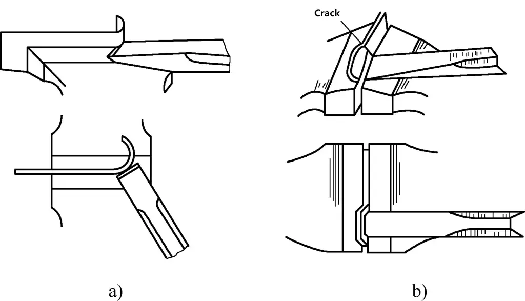
a) Correct
b) Incorrect
When cutting large-sized sheet metal on an anvil, place a soft iron pad underneath to prevent damage to the chisel edge.
To chisel curved sheet metal, generally first drill a series of closely spaced holes along the contour line, then gradually cut through with a flat chisel.
3. Safety precautions when chiseling
- Before chiseling, the workpiece must be firmly clamped, with the part protruding from the vise jaws typically 10-15mm high, and a cushion should be placed underneath.
- When chiseling brittle metals, chisel from both edges towards the center to prevent edge chipping or cracking.
- During chiseling, use a protective screen in front to prevent flying chips from causing injury, and the operator should wear safety goggles.
- Use a brush to remove chisel chips, do not wipe with hands or blow with mouth.
- During chiseling, prevent the chiseling area from slipping. For this, sharpen the chisel promptly when it becomes dull, and maintain the correct wedge angle.
- If there are noticeable burrs on the chisel head, grind them off promptly.
- When chiseling, do not point the chisel and hammer towards others. Do not wear gloves on the hand holding the hammer during operation to prevent the hammer from slipping and causing injury.
- If the hammer handle becomes loose or damaged, secure it immediately or replace it. Also, the hammer handle should not be oily to prevent the hammer head or the entire hammer from flying off and causing injury.
4. Types of defects in chiseled flat surfaces and their causes (see Table 3)
Table 3 Types of defects in chiseled flat surfaces and their causes
| Type of defect | Causes |
| Rough surface | 1. Chisel edge is chipped or curled and not sharp 2. Uneven hammer strikes 3. The chisel head has been hammered flat, causing the direction of force to change constantly |
| Uneven surface | 1. The back angle is too large in a certain section during chiseling, causing the chiseled surface to be concave 2. The back angle is too small in a certain section during chiseling, causing the chiseled surface to be convex |
| Surface with ridges | 1. The left hand did not position and hold the chisel correctly, causing the chisel edge to be tilted, and the edge angle to dig in when chiseling again 2. The chisel edge was ground to be concave in the middle during sharpening |
| Chipping and corner collapse | 1. Not turning the chisel around when reaching the end, causing edge chipping 2. Taking too large a cut, causing corner collapse |
| Dimensional inaccuracy | 1. Inaccurate dimensions when starting to chisel 2. Lack of timely measurement and inspection |
IV. Filing
Using a file to remove excess metal from the surface of a part to achieve the required dimensions, shape, and surface roughness as specified in the drawing is called filing. It can be used for fine machining of parts after chiseling or sawing. It is suitable for both flat and curved surface processing.
Filing is a relatively fine manual processing method, with an accuracy of up to 0.01mm and a surface roughness of up to Ra0.8μm. Filing is one of the main operating methods in fitter work, a basic skill for fitters, and is frequently used in production.
1. File
Files are made of high carbon tool steel T12 or T13 and are quench-hardened, generally with a hardness of 62-67HRC. File teeth come in single-cut and double-cut patterns.
Single-cut files have teeth in only one direction and are generally used for filing soft metals such as aluminum and tin, or for surfaces requiring a smoother finish.
Double-cut files have teeth arranged in two intersecting directions. According to the manufacturing process, the shallower teeth cut first are the bottom teeth, which form a 55° angle with the file’s centerline; the deeper teeth cut later are the top teeth, which form a 75° angle with the file’s centerline. Due to the different angles of the bottom and top teeth, the file marks do not overlap during filing, resulting in a smoother surface.
If the bottom and top tooth angles were the same, the file teeth would align along the file’s centerline without staggering, resulting in grooves on the filed surface and a rougher finish. The fineness of file teeth is expressed by the size of the tooth spacing. The grades of fineness are classified as follows:
(1) No. 1 cut
Used for coarse files, with a tooth spacing of 2.3-0.83mm.
(2) No. 2 cut
Used for medium files, with a tooth spacing of 0.77-0.42mm.
(3) No. 3 cut
Used for fine files, with a tooth spacing of 0.33-0.25mm.
(4) No. 4 cut
Used for extra fine files, with a tooth spacing of 0.25-0.20mm.
(5) No. 5 cut
Used for superfine files, with a tooth spacing of 0.20-0.16mm.
The choice of file coarseness generally depends on the workpiece’s machining allowance, required processing accuracy, and material hardness. Coarse files have larger chip spaces and are generally suitable for filing soft materials, as well as workpieces with larger machining allowances or lower precision and surface roughness requirements. Fine files are the opposite.
When using fine files on soft materials, chips can easily clog the file, not only scratching the workpiece surface but also potentially rendering the file unusable in severe cases. Therefore, fine files are not suitable for filing soft metals.
To extend the life of files, do not use new files on hard metals; do not use files on quench-hardened workpieces; for forged parts with hard skin or cast parts with sand, remove these first before using a semi-sharp file; use one side of a new file first, and when it becomes dull, use the other side; avoid using files at excessive speeds to prevent premature wear.
Files should be regularly cleaned with a brass wire brush to remove chips from the teeth. They should also be kept away from water and oil to prevent rusting and slipping. When not in use, store files in a dry place.
2. Filing methods
(1) Draw filing
Draw filing (see Figure 15a) involves filing the workpiece in the same direction. This produces straight file marks that are neat and attractive, suitable for final polishing.
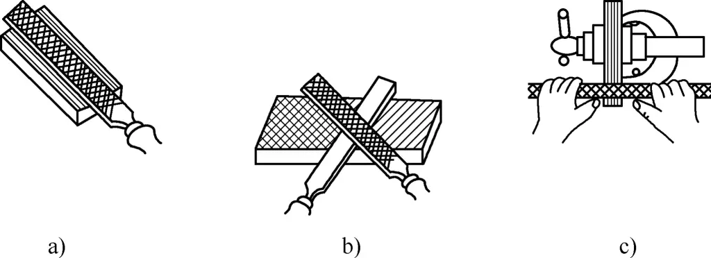
a) Draw filing
b) Cross filing
c) Traverse filing
(2) Cross filing
Cross filing (see Figure 15b) involves filing the workpiece from two intersecting directions. During filing, there is greater contact between the file and the workpiece, making it easier to keep the file steady. The file marks can also indicate high and low spots on the surface, making it easier to achieve a flat surface. Switch to draw filing when nearing completion.
(3) Traverse filing
Traverse filing (see Figure 15c) involves holding the file symmetrically with both hands and using the thumbs to push the file along the length of the workpiece. It is suitable for filing narrow, long flat surfaces and for adjusting dimensions.
When filing flat surfaces, use a metal straightedge or knife-edge straightedge to check flatness. Look for light gaps in the longitudinal, transverse, and diagonal directions to identify uneven areas.
When filing flat surfaces, especially when using large files on small flat surfaces, it can be difficult to keep the file level, often resulting in a convex middle. In this case, rub the low areas with your hand to leave a slight oil residue. When filing again, these areas will slip and be filed less, while the convex areas will be filed more, resulting in a flat surface.
When nearing the end of filing, to achieve a smoother surface, apply some chalk dust to the teeth of the fine file used for finishing. The chalk dust fills the spaces between the file teeth, reducing the depth of cut and resulting in a smoother, more even surface.
3. Reasons for convex surfaces when filing flat surfaces
- During filing, if the force applied by both hands cannot keep the file balanced, and if the left hand applies too much pressure at the beginning of the stroke, the front of the file is pressed down, causing more material to be removed from the front and back of the workpiece and less from the middle, resulting in a convex surface.
- Incorrect filing posture can cause uneven material removal across the entire surface.
- If the file itself is concave, it will produce a convex surface on the workpiece.
V. Drilling
The operation of using a drill bit to create holes in materials is called drilling.
Regardless of the type of machine, parts cannot be assembled without holes. When connecting two or more parts together, various holes need to be drilled, and then screws, rivets, or other fasteners are used to connect them. Therefore, drilling plays an important role in production.
During drilling, the workpiece remains stationary while the drill bit simultaneously performs rotational and downward movements, which are the cutting motion and the feed motion into the workpiece. Since both motions occur continuously and simultaneously, the drill bit follows a helical path when drilling holes.
1. Structure of a twist drill
A twist drill is a commonly used type of drill bit, consisting of a shank, neck, and working part, as shown in Figure 16.
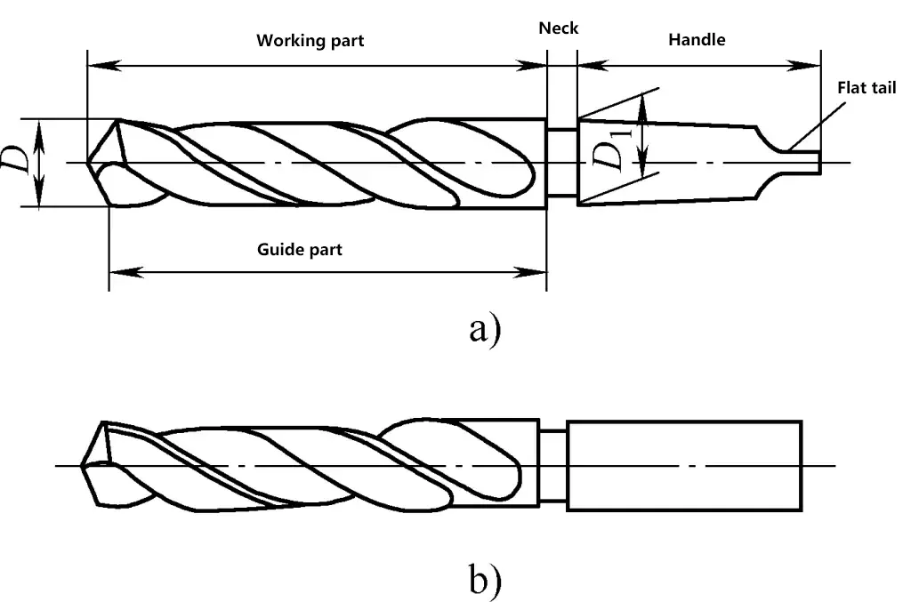
a) Taper shank
b) Straight shank
The working part of a twist drill can be divided into the cutting portion and the guiding portion. The cutting portion performs the main cutting work and has two main cutting edges, one chisel edge, two rake faces, and two flank faces. As shown in Figure 17, the guiding portion maintains the drill’s straight drilling direction during the cutting process and also serves as a backup for the cutting portion.
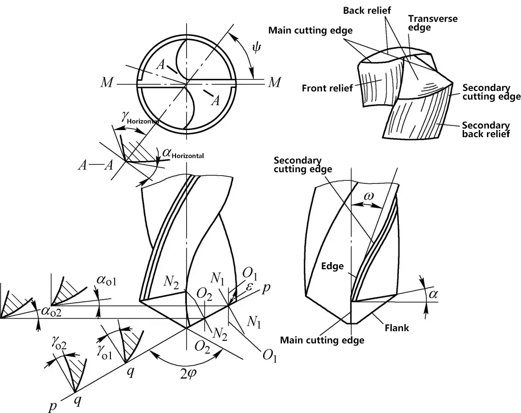
The guiding portion also functions to smooth the hole wall and helps with chip removal and cutting fluid delivery. It has two spiral flutes and two narrow spiral margins, with the flute surfaces intersecting to form two edges (secondary cutting edges). The drill’s diameter gradually decreases from the tip towards the shank, with a taper of typically 0.05-0.10mm over a 10mm length, which reduces friction between the drill and the hole wall.
The solid part along the axis of the twist drill’s working section is called the drill core. Its function is to connect the two spiral flutes to maintain the strength and rigidity of the drill bit. The drill core gradually enlarges from the cutting part towards the shank.
The material of the working part of the drill bit is generally made of high-speed steel, quenched to 62-68 HRC.
2. Geometric parameters of the twist drill cutting part
As shown in Figure 17, the cutting plane during drilling is the p-p plane in the figure, and the base plane is q-q. The two planes are perpendicular to each other. The geometric parameters of the twist drill during cutting are as follows:
(1) Point angle (2φ)
The point angle is the angle formed by the projections of the two main cutting edges of the drill on its parallel plane M-M, also known as the tip angle or point angle. The point angle of a standard twist drill is 2φ = 118° ± 2°.
The choice of point angle is related to the nature of the material. The point angle affects the back force on the main cutting edge; the smaller the point angle, the smaller the feed force, and at the same time, the larger the edge angle at the outer edge of the drill, which is beneficial for heat dissipation and improving the life of the drill.
However, under the same conditions, reducing the point angle will increase the cutting torque on the drill and cause difficulties in chip evacuation and hinder the entry of cutting fluid. Generally, a larger point angle is chosen for drilling hard materials compared to soft materials. The selection of twist drill cutting angles is shown in Table 4.
Table 4 Selection of twist drill cutting angles [Unit: (°)]
| Drilling material | Point angle 2φ | Relief angle αo | Helix angle ω |
| General steel materials | 116~118 | 12~15 | 20~32 |
| General ductile steel materials | 116~118 | 6~9 | 20~32 |
| Aluminum alloy (deep hole) | 118~130 | 12 | 32~45 |
| Aluminum alloy (through hole) | 90~120 | 12 | 17~20 |
| Soft brass and bronze | 118 | 12~15 | 10~30 |
| Hard bronze | 118 | 5~7 | 10~30 |
| Copper and copper alloys | 110~130 | 10~15 | 30~40 |
| Soft cast iron | 90~118 | 12~15 | 20~32 |
| Cold (hard) cast iron | 118~135 | 5~7 | 20~32 |
| Quenched steel | 118~125 | 12~15 | 20~32 |
| Cast steel | 118 | 12~15 | 20~32 |
| Manganese steel [w(Mn)=7%~13%] | 150 | 10 | 20~32 |
| High-speed steel | 135 | 5~7 | 20~32 |
| Nickel steel (250~400HBW) | 135~150 | 5~7 | 20~32 |
| Wood | 70 | 12 | 30~40 |
| Hard rubber | 60~90 | 12~15 | 10~20 |
(2) Rake angle (γo)
It is the angle between the rake face and the base plane in the orthogonal plane N1-N1 or N2-N2 (a plane passing through any point on the main cutting edge and perpendicular to the cutting plane and base plane), i.e., γo1, γo2 in the figure.
The rake angle increases towards the outer diameter along the main cutting edge, being 30° at the outer edge and -30° near the chisel edge, and -60° on the chisel edge. The larger the rake angle, the easier the cutting, but the lower the strength of the cutting part.
(3) Relief angle (αo)
The relief angle is the angle between the flank face and the cutting plane in the cylindrical section O1-O1 or O2-O2 (αo1, αo2 in the figure). The relief angle is also not equal at every point on the cutting edge, contrary to the rake angle, with the smallest relief angle at the outer edge and the largest at the center.
The smaller the relief angle, the more severe the friction between the drill and the workpiece’s cutting surface during drilling; the larger the relief angle, the sharper the drill, but the cutting edge strength is weakened, affecting the drill’s life, and it’s also prone to vibration during drilling, resulting in polygonal holes.
When drilling hard materials, the relief angle can be slightly smaller to ensure the strength of the cutting edge; when drilling soft materials, the relief angle can be slightly larger. However, when drilling non-ferrous metals, the relief angle should not be too large, otherwise it may cause plunging.
(4) Helix angle (ω)
The helix angle is the angle between the tangent line of the spiral at the outermost edge of the main cutting edge and the drill’s axis, generally 18°~30°. Smaller angles are used for small diameter drills to improve strength.
The helix angle is not constant at different outer diameters of the drill, gradually decreasing from the outer edge to the center. The helix angle is generally represented by the value at the outer edge.
(5) Chisel edge angle (ψ)
The chisel edge angle is the angle between the chisel edge and the parallel axial section M-M of the main cutting edge. Its size is related to the size of the relief angle. When the relief angle of the drill increases after grinding, the chisel edge angle becomes smaller, and correspondingly, the length of the chisel edge becomes longer. Therefore, when grinding a twist drill, the chisel edge angle can be used to judge whether the relief angle near the drill core is ground correctly. The chisel edge angle of a standard twist drill is ψ = 50°~55°.
3. Grinding of twist drills
The purpose of drill grinding is to reshape the dull or damaged cutting parts into the correct geometric shape, or when the workpiece material changes, the cutting parts and angles of the drill also need to be reground to maintain good cutting performance.
The cutting part of the drill has a direct impact on the quality and efficiency of drilling. Drills of the same material and specifications can have much higher service life, efficiency, and precision when ground by experienced workers.
After grinding a twist drill, check if the point angle 2φ is correct, and the length and height of the two cutting edges should be the same to ensure vertical drilling. Check if the relief angle αo at the outer edge and center of the drill meets the requirements. During grinding, to avoid tempering of the cutting edge, the drill must be frequently cooled in water to maintain the hardness of the cutting part.
4. Drill modification
To adapt to drilling different materials and meet different drilling requirements, as well as to improve the performance of the drill, the shape of the cutting part of the drill needs to be modified. The modification of twist drills is shown in Figure 18.
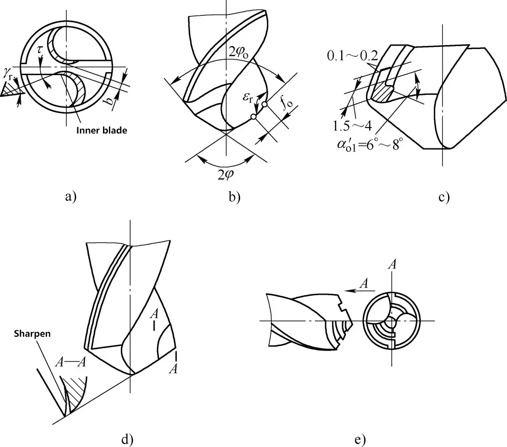
a) Modifying the chisel edge
b) Modifying the point angle
c) Modifying the edge
d) Modifying the rake face
e) Creating chip-breaking grooves
(1) Modifying the chisel edge
(See Figure 18a) The purpose is to shorten the chisel edge, increasing the rake angle near the drill center. Generally, drill bits with diameters over 5mm need to have their chisel edges ground. After grinding, the length of the chisel edge should be 1/3 to 1/5 of the original length, forming an inner edge with an inclination angle τ=20°~30°, and a rake angle γτ=0°~15° at the inner edge. After grinding the chisel edge, cutting conditions improve and centering action is strengthened.
(2) Grinding the point angle of the main cutting edge
(See Figure 18b) Generally, the point angle 2φo=70°~75°, fo=0.2D (D is the hole diameter).
(3) Grinding the margin
(See Figure 18c) On a section of the margin near the main cutting edge, grind a 6°~8° secondary clearance angle while retaining 1/3 to 1/2 of the original margin width to reduce friction and improve drill bit life.
(4) Grinding the rake face
(See Figure 18d) Grind off a portion of the rake face at the intersection of the main and secondary cutting edges to reduce the rake angle in this area, improve cutting edge strength, and prevent drill wandering.
(5) Grinding chip-breaking grooves
(See Figure 18e) After grooving, wide chips become narrower, facilitating chip evacuation.
5. Cutting fluids and cutting parameters for drilling
(1) Cutting fluids for drilling
During the cutting process, drill bits generate a large amount of heat, which can easily cause the cutting edge to anneal, resulting in severe damage and loss of cutting ability. When drilling, to reduce cutting temperature, increase lubrication performance, improve drill bit life, hole quality, and efficiency, appropriate cutting fluid should be selected based on the workpiece material properties.
Cutting fluid should be continuously applied from the moment the drill bit enters the metal. Except when drilling cast iron and small diameter holes, cutting fluid should generally be used for all other materials. When using cutting fluid, it must be applied to the interior of the hole, where the cutting action occurs. Refer to Table 5 for cutting fluid selection in drilling.
Table 5 Cutting fluid selection for drilling
| Workpiece material for drilling | Cutting fluid |
| Carbon steel, cast steel, malleable cast iron | 3%~5% emulsion or machine oil |
| Alloy steel | Sulfurized cutting oil or 3%~5% emulsion |
| General cast iron | No cutting fluid |
| Chilled cast iron | Kerosene |
| Brass and bronze | No cutting fluid or 5%~8% emulsion |
| Aluminum and aluminum alloys | No cutting fluid or emulsion |
| Hard rubber, bakelite, fiberboard | No cutting fluid |
| Magnesium alloy | 4% salt water |
| Stainless steel | 3% soap plus 2% linseed oil water solution or sulfurized cutting fluid |
| Tool steel | 3%~5% emulsion or machine oil |
(2) Selection of cutting parameters for drilling
1) Cutting elements
① Cutting speed v.
The linear speed of a point on the outer diameter of the rotating drill bit is called the cutting speed (primary motion speed). It can be calculated using the following formula:
v=πDn/1000
Where:
- v – cutting speed (m/min);
- D – drill bit diameter (mm);
- n – drill bit revolutions per minute (r/min);
Based on the above formula, we can derive:
n=1000v/(πD)=318.3v/D
② Feed rate f.
The distance the drill bit moves downward for each revolution is called the feed rate, measured in mm/r.
2) Selection of cutting parameters
Cutting parameters refer to cutting speed and feed rate. Cutting speed is related to workpiece material properties, drill bit diameter, drill bit material, feed rate, and cooling lubricant. Higher cutting speeds increase efficiency but must be appropriate.
Excessive cutting speeds can cause the drill bit temperature to rise, leading to annealing and damage to the cutting edge. Feed rate should also be appropriate, selected based on factors such as workpiece material properties. If the feed rate is too high, the cutting edge can be damaged or the drill bit may break.
Cutting parameters for drilling are often selected based on experience. Generally, for small holes, use higher speeds and lower feed rates; for large holes, use higher feed rates. For hard materials, use slower speeds and lower feed rates; for soft materials, use higher speeds and higher feed rates. When using small drill bits on hard materials, it may be appropriate to reduce the speed. Refer to Table 6 for the selection of cutting parameters for drilling.
Table 6 Cutting speeds and feed rates for high-speed drill bits drilling carbon steel (with cutting fluid)
| Feed rate f/(mm/r) | Drill diameter d/mm | ||||||||||
| 2 | 4 | 6 | 10 | 14 | 20 | 24 | 30 | 40 | 50 | 60 | |
| Cutting speed v/(m/min) | |||||||||||
| 0.05 | 46 | — | — | — | — | — | — | — | — | — | — |
| 0.08 | 32 | — | — | — | — | — | — | — | — | — | — |
| 0.10 | 26 | 42 | 49 | — | — | — | — | — | — | — | — |
| 0.12 | 23 | 36 | 43 | — | — | — | — | — | — | — | — |
| 0.15 | — | 31 | 36 | 38 | — | — | — | — | — | — | — |
| 0.18 | — | 26 | 31 | 35 | — | — | — | — | — | — | — |
| 0.20 | — | — | 28 | 33 | 38 | — | — | — | — | — | — |
| 0.25 | — | — | — | 30 | 34 | 35 | 37 | — | — | — | — |
| 0.30 | — | — | — | 27 | 31 | 31 | 34 | 33 | — | — | — |
| 0.35 | — | — | — | — | 28 | 29 | 31 | 30 | — | — | — |
| 0.40 | — | — | — | — | 26 | 27 | 29 | 29 | 30 | 30 | — |
| 0.45 | — | — | — | — | — | 26 | 27 | 27 | 28 | 29 | 27 |
| 0.50 | — | — | — | — | — | — | 26 | 26 | 26 | 27 | 26 |
| 0.60 | — | — | — | — | — | — | — | 24 | 24 | 25 | 25 |
| 0.70 | — | — | — | — | — | — | — | — | 23 | 23 | 23 |
| 0.80 | — | — | — | — | — | — | — | — | — | 21 | 22 |
| 0.90 | — | — | — | — | — | — | — | — | — | — | 21 |
VI. Reaming and Countersinking
1. Reaming
Using a reamer to enlarge existing holes in parts is called reaming. The purpose of reaming is to reduce the impact of one-time processing and improve the accuracy of the processed hole. Reaming is generally used as preparation for boring.
Generally, for holes with a diameter D>30mm, first drill with a drill bit 0.5~0.7mm smaller than the hole diameter, then ream. For holes with higher requirements, reaming can be done twice to improve quality.
The structure of a reamer is similar to a twist drill, equivalent to flattening the end of a twist drill (removing the chisel edge). Reamers usually have 3-4 cutting edges, thus having better guiding performance, ensuring correct reaming direction, and can achieve smaller surface roughness values, as shown in Figure 19.

2. Countersinking
Using the countersinking method to process flat-bottomed or conical countersinks (or bosses) is called countersinking. The main tools used for countersinking are cylindrical counterbores, conical countersinks, and face mills, as shown in Figure 20.
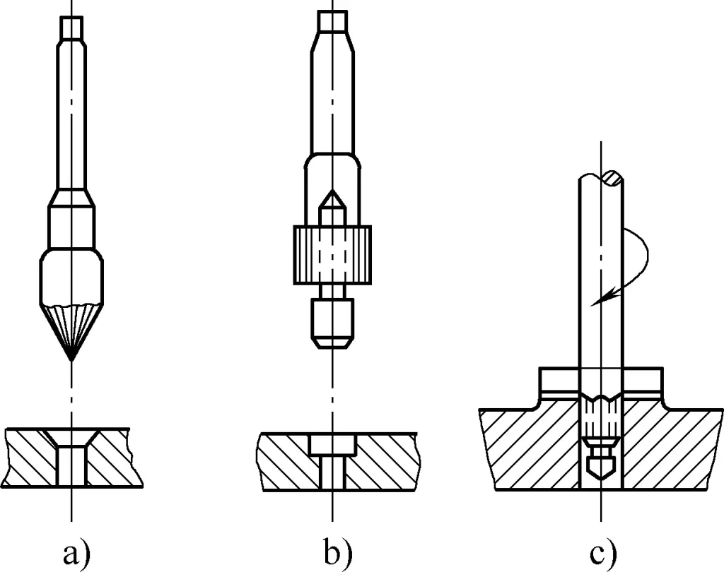
a) Conical countersink
b) Cylindrical counterbore
c) Face mill
(1) Cylindrical counterbore
Its end face cutting edge plays the main cutting role. The rake angle and helix angle of the counterbore are the same, generally 15°, and the clearance angle is generally 8°. The cutting edge on the outer circle serves to polish the hole wall, with a secondary clearance angle generally of 8°. The front end of the counterbore is a guide pillar, which can ensure centering and guiding.
A more commonly used cylindrical counterbore has cutting edges made of cemented carbide, and the guide pillar can rotate relative to the center. Since there is no relative sliding between the guide pillar and the workpiece, it won’t damage the workpiece hole during cutting.
(2) Conical countersink
Its conical angle has four types: 60°, 75°, 90°, and 120°, which can be selected according to workpiece requirements, with 90° being the most commonly used. The large end diameter d of the cone is 12~60mm, and the number of teeth is generally 4~12. Conical countersinks can also be modified from twist drills, but the effect is not as good as dedicated conical countersinks.
Vibration is easily produced during countersinking, so attention should be paid during processing: countersinks modified from twist drills should be as short as possible, and when grinding, care should be taken to ensure that the two cutting edges are of equal length and symmetrical angles; the clearance angle and rake angle at the outer edge of the countersink should be appropriately reduced.
The cutting speed should be slower than when drilling. Higher speeds lead to more severe vibration patterns. To avoid this, the cutting speed for countersinking should be kept at 1/3~1/2 of the drilling speed. Generally, manual feed is adopted, with slower withdrawal. During operation, some machine oil can be added to the guide pillar and cutting surface for lubrication. These measures can reduce vibration and improve countersinking quality.
VII. Reaming
To improve the accuracy of holes and reduce the surface roughness of hole walls, using a reamer for fine machining is called reaming. Reaming is widely used in mechanical parts. Some holes require high precision and low surface roughness values, many of which need to be processed by reamers. Reaming is easier to ensure precision and has higher efficiency compared to other processing methods, especially suitable for processing small holes and tapered holes with high precision requirements.
1. Reamer
Reamers are divided into machine reamers and hand reamers according to their use method, as shown in Figure 21. The main differences between machine reamers and hand reamers are: the former has a shorter working part, fewer teeth, and a longer shank; the latter is the opposite. According to different uses, reamers can be divided into cylindrical reamers and tapered reamers. Cylindrical reamers are further divided into fixed reamers and adjustable reamers.
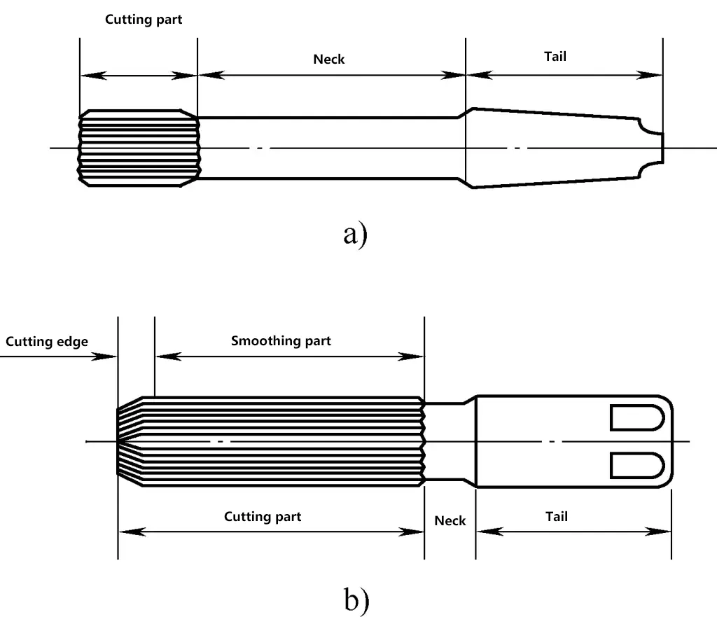
a) Machine reamer
b) Hand reamer
A reamer is a multi-edge cutting tool, and its structure mainly consists of cutting part, neck, and tail. The number of teeth ranges from 4 to 12 depending on the diameter of the reamer.
The shape of the cutting edge is wedge-shaped. Because its cutting amount is very small, the rake angle is 0°, serving a scraping function. If high precision is required, it can be changed to a negative rake angle. The rake angle is generally -5° to 0°. The clearance angle should not be too large as it relates to the strength of the cutting edge (the smaller the clearance angle, the higher the strength). Generally, the clearance angle is 8° for reaming hard materials and 5° for brittle materials.
For accurate measurement, the number of cutting edges is always even, but distributed unevenly to ensure smooth and stable cutting of the reamer and prevent chatter marks on the hole wall. The cutting edges of the reamer are shown in Figure 22. The polishing part of the reamer serves to ensure the centering of the reamer, polish the hole wall, and act as the ground part. The top of the reamer teeth has a 0.3~0.5mm wide edge band for aligning the hole position.
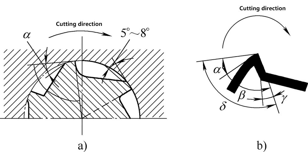
a) Cutting edge with 0° rake angle
b) Cutting edge with negative rake angle
2. Reaming bar (Reamer wrench)
A reaming bar is a tool for manual reaming, with the adjustable type being commonly used. During processing, the reamer shank tail is firmly placed, and the square tenon is clamped in the square hole of the reaming bar. The reaming bar is turned to rotate the reamer. The square hole of this type of reaming bar is adjustable, that is, by turning the movable handle, the slider moves back and forth, expanding or contracting the square hole to accommodate reamer square heads of different sizes.
3. Cutting allowance and cutting fluid for reaming
The previous process before reaming must leave a certain machining allowance for reaming. The reaming machining allowance should be appropriate for the reamed hole wall to be smooth. If the allowance is too large, it can easily cause wear on the reamer, affecting the surface roughness and accuracy of the hole, and may also result in a polygonal shape. Therefore, a reasonable reaming allowance should be left.
The size of the reaming allowance is generally as follows: If one reamer is used to ream the hole in one pass, and the hole diameter is below 20mm, the reaming allowance is 0.1~0.2mm. If rough reaming and fine reaming are used to ream the hole in two passes, for hole diameters of 5~80mm, the rough reaming allowance is 0.25~0.5mm, and the fine reaming allowance is 0.05~0.15mm.
When the reamer is working, there is a lot of friction between its back face and the hole wall, so cutting fluid must be used during reaming. This can reduce friction, ensure a smaller surface roughness value for the hole surface, prevent the reamer from expanding due to heat and enlarging the hole diameter, and can also extend the life of the reamer. The cutting fluid used for reaming is the same as for drilling.
4. Reaming methods and precautions
- Determine the number of reaming passes and select the reamer according to requirements.
- Before reaming, the workpiece should be clamped correctly. After the reamer is installed on the reaming bar, insert the reamer into the hole and use a square to check, ensuring the reamer is perpendicular to the end face of the hole. Hold the handle of the reaming bar with both hands, apply slight and balanced pressure, and turn the reaming bar clockwise to perform reaming.
- Reverse rotation is strictly prohibited during reaming. If the reamer becomes difficult to rotate during reaming, forcefully lift the reamer upwards in the original rotation direction, investigate the cause, and address it promptly.
- The reamer is a finishing tool. After use, clean off the chips, apply oil, and store it in a dedicated box to prevent rusting or damage.
- The dimensional accuracy and surface quality of the hole are mainly obtained from the tool. Therefore, during the machining process, it is necessary to calculate the dimensional accuracy of the hole and observe its surface quality in order to replace the tool in a timely manner.
VIII. Thread Tapping
1. The concept of threads
Various types of threads can be found on any machine. Some of these threads are turned on machine tools, while others are roll-formed. Precision threads can be milled on machining centers or even ground on thread grinding machines. In addition to mechanical processing, fitters often use manual thread tapping in assembly and maintenance work. Thread tapping is generally suitable for processing ordinary threads with relatively small diameters.
Using a tap to process internal threads is called thread tapping. Before introducing thread tapping, we will first introduce the structure, types, and various elements of threads, as well as the standards for ordinary threads that fitters frequently encounter.
(1) The concept of a helix
If a paper right-angled triangle is wrapped around any cylindrical body, as shown in Figure 23, where the length of one of the right-angled sides (side AB) of the paper right-angled triangle is equal to the circumference of the base circle of the cylindrical body, then the hypotenuse (side AC) forms a curve on the surface of the cylindrical body. This curve is called a helix.

The distance between the starting point and the endpoint of the helix after one complete rotation (i.e., the length of the right-angled side BC) is called the lead. The angle of elevation of the helix (the angle φ between the right-angled side AB and the hypotenuse AC) is called the helix angle (lead angle). Machining a groove of a certain shape along the helix forms a thread of a specific shape on the cylindrical surface.
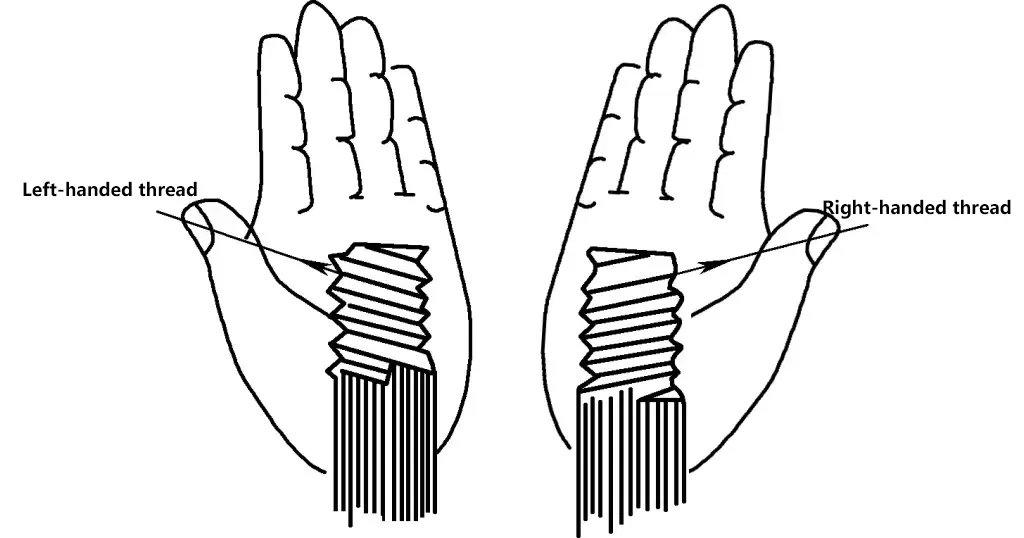
According to the direction of the thread’s winding on the cylindrical surface, threads can be classified as right-handed (positive thread) or left-handed (negative thread). A thread that rises from left to right is called a right-handed thread and is screwed in clockwise direction; the opposite is called a left-handed thread, as shown in Figure 24. Depending on different uses, the number of thread lines on the cylindrical surface can be single, double, or multiple. The more thread lines, the faster the transmission speed.
(2) Thread elements and main dimensions of threads
1) Thread elements
Thread elements include thread form, major diameter, pitch, lead, number of starts, tolerance, and direction of rotation. Threads are machined based on these elements.
2) Thread form
Thread form refers to the shape in the axial section of the thread, as shown in Figure 25.
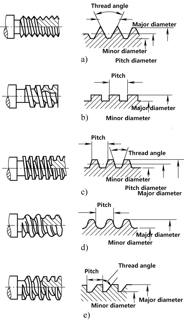
a) Common thread
b) Square thread
c) Trapezoidal thread
d) Rounded thread
e) Buttress thread
3) Main dimensions of threads
Taking common threads as an example, the main dimensions of threads are shown in Figures 26 and 27.
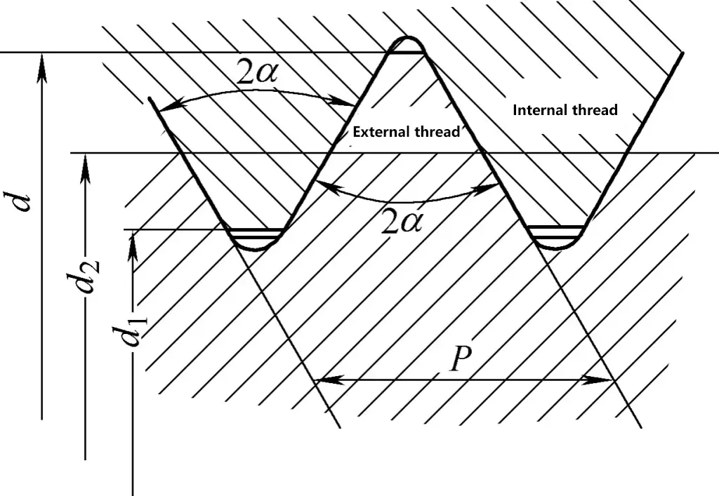
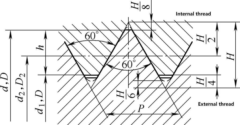
- Major diameter. The major diameter is the largest diameter of the thread (i.e., the crest diameter d of external threads, the root diameter D of internal threads), which is the nominal diameter of the thread.
- Minor diameter. The minor diameter is the smallest diameter of the thread (i.e., the root diameter d1 of external threads, the crest diameter D1 of internal threads).
- Pitch diameter (d2, D2). The effective diameter of the thread is called the pitch diameter. At this diameter, the thread thickness and groove width are equal, i.e., the thread thickness is half of the pitch (the pitch diameter is the average of the major and minor diameters).
- Thread profile height (h). The distance from the crest to the root of the thread perpendicular to the thread axis is called the thread profile height.
- Thread angle (α). The angle formed by the two sides of the thread profile is called the thread angle.
- Pitch (P). The axial distance between corresponding points on two adjacent threads measured along the neutral line is called the pitch.
- Lead (Ph). The distance a point on the thread moves along the axis when the thread makes one complete revolution is called the lead. For single-start threads, the lead is equal to the pitch. The relationship between lead and pitch can be expressed as: Lead of multi-start threads (Ph) = Number of starts (z) × Pitch (P)
(3) Thread applications and designations
1) Range of thread applications
- Ordinary threads are widely used, for example, in connecting bolts and nuts for equipment.
- Trapezoidal threads and square threads are mainly used in transmission and high-load machinery, such as the threads on bench vises, machine tool lead screws, jack screws, etc.
- Pipe threads are mainly used for pipe connections, such as the threads on water pipe fittings.
- Buttress threads are used in machinery subjected to unidirectional pressure, such as the threads on press screws.
2) Thread designations
Each type of thread has a specified standard designation.
① Ordinary threads.
The thread angle is 60°, and the unit of measurement is mm. They are divided into coarse and fine threads, with the difference being that fine ordinary threads have a smaller pitch than coarse ordinary threads of the same major diameter. GB/T 197-2003 specifies thread tolerance grades as fine, medium, and coarse. In the following cases, medium precision threads do not have their tolerance class designation marked.
- Internal threads: 5H (for nominal diameters ≤1.4mm); 6H (for nominal diameters ≥1.6mm).
- External threads: 6h (for nominal diameters ≤1.4mm); 6g (for nominal diameters ≥1.6mm).
② Pipe threads.
The thread angle is 55° or 60°, and it is represented by a size designation. For example, Rp3/4 indicates a 55° right-hand cylindrical internal thread with a size designation of 3/4.
③ Standard thread designations.
According to national standards, standard thread designations include thread characteristic code, size designation, tolerance class designation, direction of thread designation, and thread engagement length designation. Examples of standard thread designations and notations are shown in Table 7.
Table 7 Standard thread designations and notation examples
| Thread Type | Characteristic Code | Designation Example | Example Description |
| Coarse ordinary thread | M | M10 | Coarse ordinary thread, nominal diameter 10mm, tolerance class 6g |
| Fine ordinary thread | M | M10×1 | Fine ordinary thread, nominal diameter 10mm, pitch 1mm, tolerance class 6g |
| Trapezoidal thread | Tr | Tr40×14(P7)LH | Trapezoidal thread, nominal diameter 40mm, lead 14mm, pitch 7mm, left-hand |
| Buttress thread | B | B70×10 | Buttress thread, nominal diameter 70mm, pitch 10mm |
| 55° Taper internal thread | Rc | Rc3/4 | 55° Taper internal thread, size designation 3/4 |
| 55° Cylindrical internal thread | Rp | Rp5/8 | 55° Cylindrical internal thread, size designation 5/8 |
| 55° Taper external thread | R | R11 | 55° Taper external thread, size designation 1 |
Non-standard threads and special threads (such as square threads) do not have specified designations; thread elements are generally marked on the workpiece drawing (enlarged thread profile drawing).
Coarse and fine ordinary threads commonly encountered in fitter’s tapping operations are shown in Table 8 with their relevant parameters.
Table 8 Nominal diameters and pitches of ordinary threads (unit: mm)
| Nominal diameter d, D | Pitch P | |
| Coarse | Fine | |
| 3 | 0.5 | 0.35 |
| 4 | 0.7 | 0.5 |
| 5 | 0.8 | 0.5 |
| 6 | 1 | 0.75 |
| 8 | 1.25 | 1, 0.75 |
| 10 | 1.5 | 1.25, 1, 0.75 |
| 12 | 1.75 | 1.5, 1.25, 1 |
| 16 | 2 | 1.5, 1 |
| 20 | 2.5 | 2, 1.5, 1 |
| 24 | 3 | 2, 1.5, 1 |
| 30 | 3.5 | 2, 1.5, 1 |
| 36 | 4 | 3, 2, 1.5 |
| 42 | 4.5 | 3, 2, 1.5 |
| 48 | 5 | 3, 2, 1.5 |
| 56 | 5.5 | 4, 3, 2, 1.5 |
| 64 | 6 | 4, 3, 2, 1.5 |
(4) Thread measurement
To determine thread dimensions and specifications, it is necessary to measure the major diameter, pitch, and thread profile for processing and quality inspection. Common thread measurement methods include:
- Using a vernier caliper to measure the major diameter.
- Using a thread gauge to determine the pitch and profile. Place the thread gauge on the thread being measured; once the gauge profile matches the workpiece profile, the specification marked on that thread gauge indicates the pitch of the measured thread.
2. Tapping
(1) Structure of taps
A tap consists of a threaded portion (including chamfer and land), flutes, neck, and shank, as shown in Figure 28. The threaded portion of the tap is made of high-speed steel or alloy steel and is hardened by heat treatment.
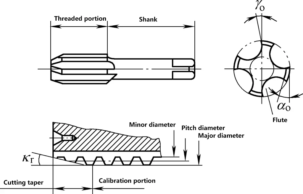
1) Chamfer
It is the conical part at the front of the tap with sharp cutting edges, serving as the main cutting section. The rake angle of the cutting edge is 8° to 10°, and the relief angle is 4° to 6°.
2) Land
It determines the diameter of the threaded hole, finishes the thread surface, guides the axial movement of the tap, and serves as a reserve for regrinding. Its relief angle is 0°.
3) Flutes
They serve to accommodate and remove chips and form cutting edges. Common taps have 3 or 4 flutes.
4) Shank
Its shape and function are the same as those of a hand reamer.
(2) Types and applications of taps
1) Hand taps
Hand taps generally come in sets of two or three. Taking a set of taper taps as an example, it can be divided into taper, second, and bottoming taps. Each tap has a different chamfer angle, and the major diameter of the land also varies.
① Three-piece tap set
The taper tap has a chamfer angle of 4° to 5°, with 5 to 7 incomplete threads in the chamfer, completing 60% of the total cutting work; the second tap has a chamfer angle of 10° to 15°, with 3 or 4 incomplete threads in the chamfer, completing 30% of the total cutting work.
The fine taper cutting angle is 18° to 23°, with 1 or 2 incomplete threads in the cutting taper, completing 10% of the total cutting work. Since the three-piece tap set cuts threads in three passes, the total cutting volume is divided into three parts, thereby reducing the cutting area and resistance, making threading easier and resulting in smoother thread surfaces. It also prevents tap breakage and damage to the cutting edges.
② Two-piece tap set
The lead taper cutting angle is 7°, with about 6 incomplete threads; the second taper cutting angle is 20°, with about 2 incomplete threads.
③ Application
Usually, for threading M6 to M12, a set has two taps; for threading below M6 and above M24, a set has three taps. This is because taps for small threads have lower strength and are prone to breakage, so three are provided; while taps for large threads have a high cutting load and require gradual cutting in several passes, so they are also made in sets of three. Fine pitch standard thread taps come in sets of two regardless of size specifications.
2) Pipe thread taps
These are further divided into straight pipe thread taps and tapered pipe thread taps. Straight pipe thread taps have a shorter working part and come in sets of two; tapered pipe thread taps are single pieces, but larger sizes may also come in sets of two. Pipe thread taps are used for cutting threads on pipe fittings and similar applications.
3) Machine taps
Machine taps are used for mechanical thread cutting. For easy clamping, the tap shank is longer. Generally, machine taps are single pieces, completing the threading in one pass. They have a larger cutting taper angle and are longer, suitable for threading long holes but not for shallow holes. Machine taps can also be used for manual threading.
(3) Tap wrenches
When using hand taps for threading, it is essential to use a tap wrench to hold the tap. Tap wrenches are divided into two categories: regular tap wrenches and T-handle tap wrenches. Each type is further divided into fixed and adjustable tap wrenches.
1) Fixed tap wrenches
These tap wrenches have handles at both ends and a square hole in the middle that fits one size of tap square. Since the size of the square hole is fixed, it does not fit multiple sizes of tap squares. When using, choose different specifications of tap wrenches according to the size of the tap.
The advantage of this type of tap wrench is that it is easy to manufacture. You can simply drill a hole in a piece of iron bar and file it into a square hole of the required size. It is suitable for frequent threading of a specific size.
2) Adjustable tap wrenches
The square hole size of this type of tap wrench can be adjusted to fit different sizes of tap squares, making it very convenient to use.
Common tap wrench specifications are shown in Table 9.
Table 9 Common tap wrench specifications (unit: mm)
| Tap diameter | ≤6 | 8-10 | 12-14 | ≥16 |
| Tap wrench length | 150-200 | 200-250 | 250-300 | 400-450 |
3) T-handle tap wrenches
This type of tap wrench is commonly used with smaller taps. When threading near a workpiece step or inside a box, where a regular tap wrench might hit the workpiece, a T-handle tap wrench is used. Small T-handle tap wrenches are generally fixed and used for threading M6 and below. The length of the tap wrench is determined based on the workpiece requirements.
(4) Determining the drill hole diameter before threading
When tapping threads, the tap has both cutting and extrusion effects on the metal. If the thread root hole diameter is the same as the minor diameter of the thread, it can cause the metal to grip the tap, resulting in tap damage and breakage.
Therefore, the drill bit diameter for the thread root hole should be slightly larger than the minor diameter of the thread. If it’s too large, it will result in insufficient threads and create scrap. The determination of the root hole diameter is closely related to the material and can be determined by referring to Tables 10-12.
Table 10 Drill bit diameters for common thread root holes before tapping (unit: mm)
| Thread nominal diameter d | Thread pitch D | Drill bit diameter | |
| Cast iron, bronze, brass | Steel, malleable cast iron, pure copper, Laminate | ||
| 2 | 0.4 | 1.6 | 1.6 |
| 0.25 | 1.75 | 1.75 | |
| 2.5 | 0.45 | 2.05 | 2.05 |
| 0.35 | 2.15 | 2.15 | |
| 3 | 0.5 | 2.5 | 2.5 |
| 0.35 | 2.65 | 2.65 | |
| 4 | 0.7 | 3.3 | 3.3 |
| 0.5 | 3.5 | 3.5 | |
| 5 | 0.8 | 4.1 | 4.2 |
| 0.5 | 4.5 | 4.5 | |
| 6 | 1 | 4.9 | 5 |
| 0.75 | 5.2 | 5.2 | |
| 8 | 1.25 | 6.6 | 6.7 |
| 1 | 6.9 | 7 | |
| 0.75 | 7.1 | 7.2 | |
| 10 | 1.5 | 8.4 | 8.5 |
| 1.25 | 8.6 | 8.7 | |
| 1 | 8.9 | 9 | |
| 0.75 | 9.1 | 9.2 | |
| 12 | 1.75 | 10.1 | 10.2 |
| 1.5 | 10.4 | 10.5 | |
| 1.25 | 10.6 | 10.7 | |
| 1 | 10.9 | 11 | |
| 14 | 2 | 11.8 | 12 |
| 1.5 | 12.4 | 12.5 | |
| 1 | 12.9 | 13 | |
| 16 | 2 | 13.8 | 14 |
| 1.5 | 14.4 | 14.5 | |
| 1 | 14.9 | 15 | |
| 18 | 2.5 | 15.3 | 15.5 |
| 2 | 15.8 | 16 | |
| 1.5 | 16.4 | 16.5 | |
| 1 | 16.9 | 17 | |
| 20 | 2.5 | 17.3 | 17.5 |
| 2 | 17.8 | 18 | |
| 1.5 | 18.4 | 18.5 | |
| 1 | 18.9 | 19 | |
| 22 | 2.5 | 19.3 | 19.5 |
| 2 | 19.8 | 20 | |
| 1.5 | 20.4 | 20.5 | |
| 1 | 20.9 | 21 | |
| 24 | 3 | 20.7 | 21 |
| 2 | 21.8 | 22 | |
| 1.5 | 22.4 | 22.5 | |
| 1 | 22.9 | 23 | |
Table 11 Drill bit diameters for common straight pipe thread root holes before tapping
| Size code | Drill bit diameter/mm |
| 1/8 | 8.8 |
| 1/4 | 11.7 |
| 3/8 | 15.2 |
| 1/2 | 18.9 |
| 3/4 | 24.4 |
| 1 | 30.6 |
| 11/4 | 41.6 |
| 11/2 | 45.1 |
Table 12 Drill bit diameters for 55°, 60° tapered pipe thread root holes before tapping
| 55° tapered pipe thread | 60° tapered pipe thread | ||||
| Size code | Number of threads per 25.4mm n | Drill bit diameter/mm | Size code | Number of threads per 25.4mm n | Drill bit diameter/mm |
| 1/8 | 28 | 8.4 | 1/8 | 27 | 8.6 |
| 1/4 | 19 | 11.2 | 1/4 | 18 | 11.1 |
| 3/8 | 19 | 14.7 | 3/8 | 18 | 14.5 |
| 1/2 | 14 | 18.3 | 1/2 | 14 | 17.9 |
| 3/4 | 14 | 23.6 | 3/4 | 14 | 23.2 |
| 1 | 11 | 29.7 | 1 | 11.5 | 29.2 |
| 11/4 | 11 | 38.3 | 11/4 | 11.5 | 37.9 |
| 11/2 | 11 | 44.1 | 11/2 | 11.5 | 43.9 |
| 2 | 11 | 55.8 | 2 | 11.5 | 56 |
(5) Operating methods for power tapping
1) Choose an appropriate tapping safety chuck based on the workpiece material, thread depth, and tap size.
2) Select an appropriate cutting speed. Generally, smaller tap diameters use higher speeds; larger tap diameters should use lower speeds; larger thread pitches should use lower speeds. The following values can be used as a reference: general materials 6-15m/min; quenched and tempered steel or harder steel 5-15m/min; stainless steel 2-7m/min; cast iron 8-10m/min.
3) When the tap is about to enter the thread root hole, feed slowly to avoid damaging the tap teeth. When starting to cut, manually operate the feed handle, applying even pressure to help the tap enter the workpiece. Once the cutting portion is fully engaged, stop applying pressure and let the tap feed itself to avoid cutting defective threads.
4) When tapping through holes, the alignment portion of the tap should not protrude completely, otherwise reversing the tap out will cause thread damage.
5) After the tap has entered the workpiece, continuously add cutting fluid and frequently reverse or retract the tap to remove chips.
6) For threads M16 and above, consider using power tapping methods. This reduces manual labor and produces threads with better perpendicularity to the hole surface, resulting in higher quality and efficiency.
(6) Methods and precautions for tapping threads with taps
1) Drill the root hole.
Before tapping, drill an appropriate root hole in the workpiece, refer to Tables 10-12.
2) Chamfering.
After drilling, use a 90° countersink to chamfer both sides of the hole opening, making the maximum diameter of the chamfer equal to the nominal diameter of the thread. This allows the tap to enter the workpiece smoothly and prevents the thread edges from chipping when the tap exits the hole.
3) Clamp the workpiece in a bench vise.
Generally, workpieces are clamped in a bench vise for tapping, but smaller workpieces can be laid flat, held firmly with the left hand, while the right hand uses the tap for threading. Be sure to select an appropriate tap wrench based on the size of the square on the tap shank.
4) Tapping with the lead taper.
Insert the cutting tap into the workpiece hole, ensuring the tap is perpendicular to the workpiece surface. Carefully check and adjust. When starting to cut the thread, apply appropriate pressure with both hands and turn the tap clockwise (for right-hand threads) into the hole.
Once the cutting edge has engaged, stop applying pressure with your hands and use only steady rotational force to tap the thread. When tapping, apply balanced force with both hands and rotate smoothly. After every 1/2 to 1 turn, reverse the tap by 1/4 turn to break and remove chips, preventing chip clogging in the flutes, which could damage or break the tap.
5) Tapping with intermediate and finishing taps.
After tapping with the taper tap, use intermediate and finishing taps to enlarge and finish the thread.
① First, manually screw the intermediate and finishing taps into the thread cut by the taper tap to ensure proper guidance. Then use a tap wrench, following the previously described method, rotating back and forth until the thread is complete.
② Promptly remove chips from the tap and the bottom of the hole. When tapping deep holes, blind holes, or ductile metal materials, frequently withdraw the tap to clear chips from both the tap and the hole bottom. This prevents the tap from seizing or breaking in the hole.
③ Use cutting fluid correctly. To improve thread surface quality and ensure good cutting performance of the tap, refer to Table 13 for selecting cutting fluids based on different materials and requirements.
Table 13 Selection of cutting fluids for tapping
| Workpiece material | Cutting fluid |
| Cast iron | Kerosene or no cutting fluid |
| Steel | Soapy water, emulsion, machine oil, soybean oil, etc. |
| Bronze or brass | Rapeseed oil or soybean oil |
| Pure copper or aluminum alloy | Kerosene, turpentine, concentrated emulsion |
(7) Removing broken taps
When a tap breaks in the hole, different methods can be used to remove it depending on the situation.
1) If part of the broken tap protrudes from the hole, it can be removed using pliers or gently pried out with a sharp chisel or center punch, as shown in Figure 29. This method is suitable for smaller taps that are not too tightly stuck.
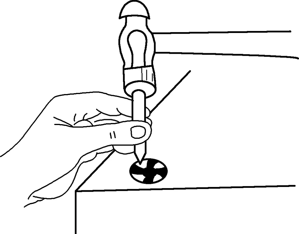
If the broken tap is too tightly stuck and cannot be removed using the above method, a bent rod or nut can be gas welded to the top of the broken tap. Then, rotate the bent rod or use a wrench to turn the nut to remove the broken tap, as shown in Figure 30. For smaller broken taps, a welding rod can be quickly spot-welded to the tap, then bent and used to extract it.

2) When the broken part of the tap is inside the hole, two nuts can be screwed onto the square end of the broken tap. Then, insert several pieces of wire between the tap flutes and the nuts. Use a wrench to rotate counterclockwise to remove the broken tap, as shown in Figure 31. The wire diameter depends on the size of the tap flutes. When using this method to remove the broken tap, apply a lubricant such as lubricating oil.
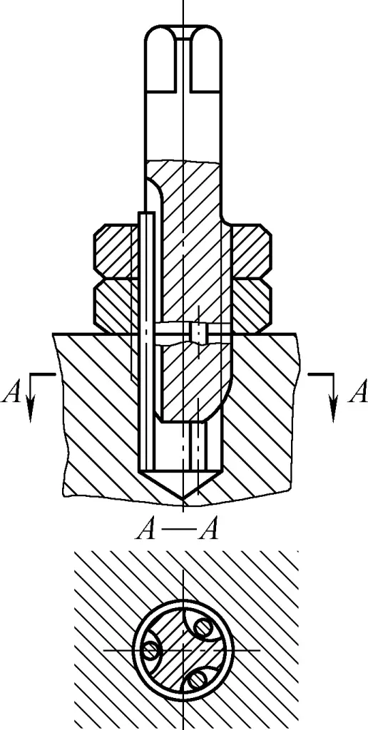
3) If the above methods fail to remove the broken tap, and if conditions allow, electrical discharge machining can be used to remove it, though this may be limited by equipment and workpiece size. Alternatively, the broken tap can be annealed and then drilled out, but this method is only suitable when enlarging the threaded hole is acceptable.
Sometimes broken taps can be difficult to remove, resulting in the scrapping of the threaded hole or workpiece. Therefore, when tapping threads, strictly follow the operating procedures and requirements, work carefully and meticulously to prevent tap breakage.
(8) Causes of scrap parts and tap breakage during thread tapping, and prevention methods (Table 14, Table 15)
Table 14 Causes of scrap parts during thread tapping and prevention methods
| Type of scrap | Causes | Prevention methods |
| Crossed threads | 1. Pilot hole diameter too small, tap cannot enter, causing crossed threads at the hole entrance 2. After tapping with the taper tap, the intermediate tap is not aligned properly, causing misalignment between taper and intermediate taps 3. Threaded hole is severely skewed, and forcing the tap cannot correct it 4. No cutting fluid used when tapping low-carbon steel and materials with good plasticity 5. Tap’s cutting cone is dull 1. Carefully check the pilot hole, select an appropriate drill bit, and enlarge the pilot hole before tapping | 2. First, manually screw the intermediate tap into the threaded hole to align the taper and intermediate taps 3. Maintain alignment between the tap and pilot hole center, apply balanced force with both hands during operation, and do not force correction if severely skewed 4. Use cutting fluid 5. Sharpen the tap’s relief angle Skewed threaded hole |
| 1. Tap is not perpendicular to the workpiece surface | 2. Large sand holes in castings 3. Uneven force applied by hands during tapping, leaning to one side 1. Ensure the tap is perpendicular to the workpiece surface when starting to cut, pay attention to checking and adjusting | 2. Check the pilot hole before tapping; if sand holes are too large, tapping is not recommended 3. Maintain balanced force with both hands throughout the process, avoid swinging Thread height insufficient |
| Pilot hole diameter is too large | Correctly calculate and select the pilot hole and drill bit diameter | Table 15 Causes of tap breakage during thread tapping and prevention methods |
Causes of breakage
| Prevention methods | 1. Pilot hole too small when tapping |
| 1. Correctly calculate and select pilot hole diameter | 2. Tap is too dull, workpiece material is too hard |
| 2. Sharpen the tap’s relief angle | 3. Tap wrench is too large, resulting in high torque; operator’s hand sensitivity is poor, often failing to notice when the tap is stuck and continuing to turn, causing the tap to break |
| 3. Select an appropriate size tap wrench, pay attention to emerging issues and address them promptly | 4. Failure to clear chips from tap flutes in time, especially with highly ductile materials, causing chips to clog in the hole |
| 4. Reverse the tap as required to break chips, remove them promptly, or withdraw the tap to clean out chips 5. No cutting fluid used when tapping highly ductile materials (such as stainless steel), causing the workpiece and tap to seize | 5. Use cutting fluid |
| 6. Tap is skewed, causing excessive force on one side | 6. Use a square to align the tap before tapping, ensuring it remains perpendicular to the workpiece |
| 7. When tapping blind holes, the tap tip contacts the hole bottom, but rotation continues, causing the tap to break | 7. Mark the depth beforehand, observe the tap’s insertion depth while tapping, prevent contact with the bottom, and remove chips regularly |
| IX. Scraping | Scraping is a finishing method that uses a scraper to remove a very thin layer of metal from the workpiece surface. It is a machining method that cannot be replaced by other processes. |
IX. Scraping
Scraping is a finishing method that uses a scraper to remove a very thin layer of metal from the workpiece surface. It is a machining method that cannot be replaced by other processes.
When scraping, first lap the workpiece against a reference piece. An indicating compound reveals high and secondary high points on the workpiece’s lapped surface. Then use a scraper to repeatedly push and remove these points. This micro-cutting process cuts and compresses the workpiece surface structure, gradually increasing contact points with the reference piece, achieving the correct geometric shape of the workpiece and good fit with the reference piece.
Scraping the surface can obtain evenly distributed pits, which is beneficial for storing lubricating oil, thus providing good lubrication conditions for the moving parts; the geometric shape of the guide rail or workpiece surface can be scraped into various special shapes such as concave or convex in the middle according to actual usage requirements. Scraping can achieve precision requirements that are difficult to achieve by general mechanical processing and eliminate errors or surface defects left by general mechanical processing.
1. Scraping tools
Scraping tools include scrapers and calibration tools.
Commonly used calibration tools include standard surface plates, calibration rulers, and squares. Among them, standard surface plates come in various specifications and are used to check wider flat surfaces. When selecting, its area should not be larger than 3/4 of the scraped surface. Various squares should be hung up for storage after use, and squares that are inconvenient to hang should be placed steadily to prevent deformation.
There are two types of scrapers: flat scrapers and curved scrapers. Scrapers are generally forged from T10A tool steel or GCr15 bearing steel, and the cutting edge must be sharp. When scraping hard materials, carbide tips can also be welded on.
Flat scrapers are divided into three types: rough scrapers, fine scrapers, and precision scrapers. After quenching, scrapers must be fine-ground on a whetstone after rough grinding on a grinding wheel. For rough scrapers, βo is 90°~92.5°, and the cutting edge must be straight; for fine scrapers, βo is 95°, with the cutting edge slightly curved; for precision scrapers, βo is 97.5°, with a smaller radius of curvature on the cutting edge than fine scrapers, as shown in Figure 32.
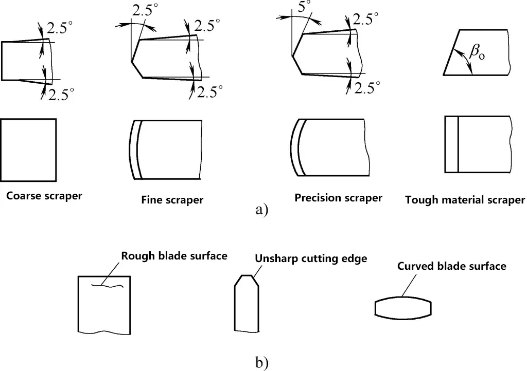
a) Angle of scraper head
b) Incorrect shape of scraper head
Curved scrapers are mainly used to scrape curved surfaces, such as the inner holes of sliding bearings. Common types include triangular scrapers and snake-head scrapers, as shown in Figure 33.
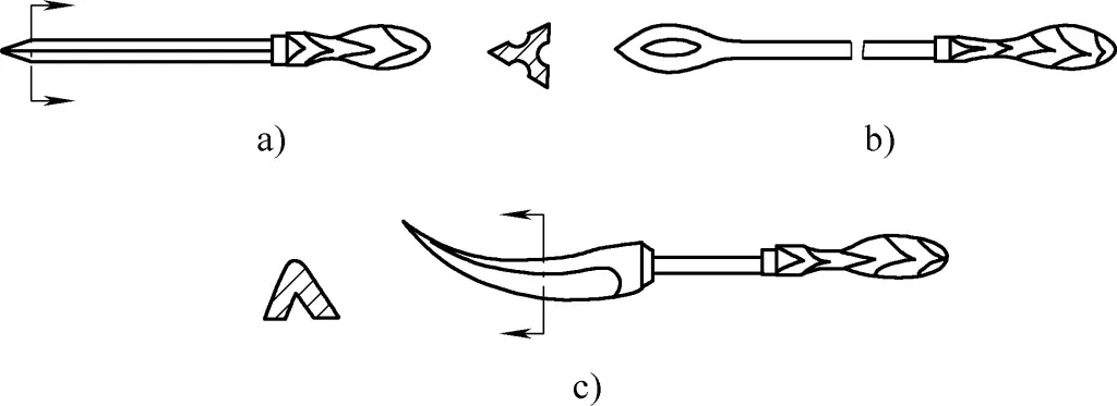
2. Spotting and precision inspection of scraping
Before scraping, it is necessary to determine the position and size of errors in the workpiece. The method is to apply a spotting agent (red lead powder) and then place the surface to be scraped together with a standard tool or matching workpiece for lapping. After lapping, the protruding parts will be highlighted, which can then be scraped off with a scraper. This method is called spotting or lapping point method. The spotting agents used are red lead powder and blue oil.
Red lead powder is divided into two types: lead oxide (orange-red) and iron oxide (reddish-brown). The red lead powder is ground into granules and mixed with machine oil for use, widely used on steel and cast iron workpieces. Blue oil is a mixture of blue powder, castor oil, and appropriate machine oil, dark blue in color, producing small and clear spotting points, mostly used for precision workpieces and non-ferrous metals and alloys.
When scraping, the spotting agent can be applied to the workpiece surface or to the calibration piece. The former shows red background with black spots (black spots are high points) on the workpiece surface, without glare and easy to see clearly, suitable for precision scraping. The latter only colors the high points on the workpiece surface, with dim spotting points that are not easy to see clearly, but chips are less likely to adhere to the cutting edge, making scraping convenient, generally chosen for rough scraping.
The correct use of spotting agents is closely related to the quality of scraping. For rough scraping, it should be mixed thinner and applied evenly on the workpiece surface, slightly thicker to make the spots larger. For precision scraping, it should be mixed thicker and applied thinly and evenly on the workpiece surface, resulting in finer spots, which is beneficial for improving scraping precision during fine scraping.
When using spotting agents, it is essential to maintain cleanliness and prevent sand particles, chips, etc., from scratching the workpiece surface. The cotton yarn used for applying spotting agents must be wrapped in sandpaper, and other application tools should also be kept clean to ensure accurate spotting.
The quality requirements for scraped surfaces generally include geometric accuracy, dimensional accuracy, contact accuracy and fit, surface roughness, etc. Commonly used inspection methods include the following two:
(1) Expressed by the number of contact points
A square frame with a side length of 25mm is placed on the surface to be inspected, and the quality is indicated by the number of contact points within the frame. The number of contact points for various plane contact accuracies is shown in Table 16.
Table 16 Number of contact points for various plane contact accuracies
| Type of plane | Number of contact points/25mm×25mm | Application examples |
| General plane | 2~5 | Fixed joining surfaces of rougher parts |
| 5~8 | General joining surface | |
| 8~12 | Machine table surfaces, general reference surfaces, machine tool guiding surfaces, sealing joining surfaces | |
| 12~16 | Machine tool guideways and guiding surfaces, tool reference surfaces, measuring instrument contact surfaces | |
| Precision plane | 16~20 | Precision machine tool guideways, straightedges |
| 20~25 | Grade 1 plane, precision measuring instruments | |
| Ultra-precision plane | >25 | Grade 0 plane, high-precision machine tool guideways, precision measuring instruments |
In curved surface scraping, it mainly involves scraping the inner holes of sliding bearings. The number of contact points for different accuracies of various sliding bearings is shown in Table 17.
Table 17 Number of contact points for different accuracies of various sliding bearings
| Bearing diameter/mm | Machine tool or precision machinery main spindle bearings | Bearings for forging equipment, general machinery | Bearings for power machinery, metallurgical equipment | ||||
| High precision | Precision | Ordinary | Important | Ordinary | Important | Ordinary | |
| Number of contact points/25mm×25mm | |||||||
| ≤120 | 25 | 20 | 16 | 12 | 8 | 8 | 5 |
| >120 | 16 | 10 | 8 | 6 | 6 | 2 | |
(2) Expressed by allowable flatness and straightness
For larger workpiece surfaces, flatness, and straightness of machine tool guideways are checked using a frame level.
Some workpieces also require checking the gap between mating surfaces using feeler gauges of specific thickness. For pressure-bearing cylinders, valve bodies, etc., air pressure or hydraulic pressure tests are also required.
3. Scraping methods and defect analysis
The scraping allowance is generally between 0.05 and 0.4mm. For larger scraping areas, a larger allowance is left. Generally speaking, the processing accuracy (straightness and flatness) of the workpiece before scraping should not be lower than the 9th grade precision specified in the national standard for geometric tolerances.
The general process of plane scraping can be divided into rough scraping, fine scraping, precision scraping, and pattern scraping.
(1) Rough scraping
Rough scraping involves using a rough scraper to uniformly remove a thicker layer of metal from the scraped surface, in order to quickly remove the rough surface or excess allowance. When scraping, a continuous pushing method can be adopted, with scraping marks forming long strips. The scraped surface is leveled according to the convex and concave error conditions. The required number of contact points for rough scraping is 2-3 points/25mm×25mm.
(2) Fine scraping
Fine scraping involves using a fine scraper to remove sparse, large research points on the scraped surface, further improving the unevenness of the scraped surface. A short scraping method is used, where the length of the scraper mark is about the width of the cutting edge. As the number of research points increases, the scraper marks should be gradually shortened. Each round of scraping should be done in a specific direction, and the second round should be done in a crosswise manner to eliminate the original direction of the scraper marks. Otherwise, the research points will appear in a striped distribution.
To increase the number of research points quickly, when scraping the points, the surrounding areas can also be scraped away. This way, when the highest points are removed, the surrounding secondary high points will quickly become visible, speeding up the scraping process.
During the scraping process, care should be taken to prevent the scraper from tilting to avoid creating deep scratches on the scraped surface. As the number of research points gradually increases, the indicator should be applied thinly and evenly. After lapping, the shiny research points (hard points) should be scraped more heavily, while the dull research points (soft points) should be scraped more lightly, until the displayed research points are evenly hard and soft.
Fine scraping requires 12-15 contact points per 25mm × 25mm area.
(3) Fine scraping
When scraping, use a fine scraping tool with a spot scraping method, where the tool mark length is about 5mm. When fine scraping, pay attention to: lightly lower the tool, quickly lift it when finishing. Only scrape once at each grinding point, do not repeat, and always scrape in a crisscross pattern.
When the contact points increase to more than 20 points/(25mm×25mm), the grinding points can be divided into three categories: completely scrape off the brightest points; scrape a small piece from the top of medium points; leave small points unscraped. In the last three passes, the crisscross tool marks should be consistent in size and neatly arranged to make the scraped surface look good.
During fine scraping, special attention should be paid to cleanliness. When lapping, impurities in the middle often cause fine lines or deep scratches on the scraped surface, making repairs very difficult and sometimes even resulting in scrap.
The width of the tool mark can reflect the depth of scraping, so controlling the width of the tool mark can control the depth of scraping. For rough scraping, the width of the tool mark should be 2/3 to 3/4 of the blade length; for fine scraping, it should be 1/3 to 1/2, and for precision scraping, it should be even narrower. Tool marks that are too wide will also affect the number of contact points per unit area.
If there are holes or threaded holes on the scraped surface, control the scraper to avoid directly scraping over the hole opening to prevent lowering it. If there is a narrow frame on the scraped surface, pay attention to keeping the angle between the scraping direction and the narrow edge less than 30° to prevent scraping the narrow edge too low.
(4) Decorative scraping
The purposes of decorative scraping are: first, purely for the aesthetics of the scraped surface; second, to create good lubrication conditions between relatively sliding surfaces, and also to judge the degree of wear on the plane based on the disappearance of the pattern. For workpieces with high contact precision requirements and many required contact points, large block patterns should not be scraped; otherwise, the required scraping precision cannot be achieved.
(5) Analysis of defects during scraping
1) Deep concave marks on the scraped surface
The reason is that the cutting edge arc of the scraper is too small, and the pressure during scraping is high, resulting in tool marks that are too deep, or uneven force is applied during rough scraping, causing the scraper to tilt.
2) Vibration marks
When scraping repeatedly in one direction or when scraping steel workpieces, if the wedge angle of the scraper is too small and the front angle is too large, vibration marks will occur.
3) Surface tearing marks
If the surface roughness of the scraper’s cutting edge is high, there are micro-cracks, or the metallographic structure at the edge becomes coarse due to excessive quenching temperature, it will cause regular rough strip-like scrape marks on the scraped surface.
4) Surface scratches
This is caused by dirty indicator, mixed impurities, or sand particles, chips, and other impurities during the grinding point process.
5) Shape accuracy errors
If the pressure is uneven when lapping grinding points, the workpiece protrudes too much from the reference piece, the workpiece mass is asymmetrical, no measures are taken during grinding points, false high points are produced, scraping is done according to false high points, or the reference piece error is too large, it will result in an inaccurate shape of the scraped surface.
X. Lapping
Lapping is a process that uses lapping tools and abrasives to remove an extremely thin layer of metal from the workpiece surface, giving the workpiece surface accurate dimensions, geometric precision, and high surface quality.
Lapping is a finishing process that is widely used in the manufacturing of tools, gauges (keyway plug gauges), and precision machinery.
1. Lapping tools and abrasives
(1) Lapping tools
Lapping tools are standard tools that determine the geometric shape of the workpiece surface during lapping. They can be made in different sizes of cylindrical, conical, ring-shaped, etc., as needed. For lapping, it is required that the geometric shape of the lapping tool be as consistent as possible with the workpiece, and the surface should be smooth and free of cracks.
During lapping, the surface hardness of the lapping tool should be slightly lower than that of the workpiece being lapped. This allows the tiny abrasive particles in the lapping compound to easily and evenly embed into the surface of the lapping tool. These fine particles have high hardness and form numerous micro-cutting edges to perform micro-cutting on the workpiece surface. Conversely, if the particles embed into the workpiece surface, they will cut the lapping tool during lapping.
However, the lapping tool should not be too soft, otherwise, the abrasive particles will completely embed into the lapping tool and lose their lapping effect. The material structure of the lapping tool should be fine and uniform, with low deformation, certain elasticity, and good wear resistance to ensure that the lapped workpiece achieves high dimensional and shape accuracy, and low surface roughness.
(2) Commonly used materials for lapping tools
Common materials for lapping tools include gray cast iron, nodular cast iron, and can also use soft steel, copper, Babbitt metal, and lead. The latter two are mainly used for polishing precision shafts made of copper alloys or lapping soft parts.
1) Gray cast iron
The best material for lapping tools, it has good lubrication properties, high lapping efficiency, is economical, and has low wear. It is particularly suitable for fine lapping, and using high-phosphorus cast iron can achieve very low surface roughness. The composition of cast iron used as lapping tool material is shown in Table 18.
Table 18 Composition of cast iron lapping tool materials
| Composition of cast iron material for precision lapping (mass fraction) | Composition of cast iron material for general rough lapping (mass fraction) | ||
| Carbon | 2.7%~3.0% | Carbon | 0.35%~3.7% |
| Manganese | 0.4%~0.7% | Manganese | 0.4%~0.7% |
| Antimony | 0.45%~0.55% | Antimony | 0.45%~0.55% |
| Silicon | 1.3%~1.8% | Silicon | 1.5%~2.2% |
| Phosphorus | 0.65%~0.7% | Phosphorus | 0.1%~0.15% |
2) Soft steel
It has higher strength than gray cast iron, is not easily broken or deformed, and is often used for lapping threads and small holes (diameter 8mm or less).
3) Copper
Mostly used for rough lapping with larger allowances.
4) Lead
Suitable for polishing soft metals.
(3) Lapping compounds
Lapping compounds are made by mixing abrasives (lapping powders) and lapping fluids. The commonly used abrasive series and their applications are shown in Table 19.
Table 19 Commonly used abrasive series and applications
| Series | Abrasive name | Code | Characteristics | Applicable range |
| Corundum | Brown corundum | A | Brown color. High hardness, high toughness, inexpensive | Rough and fine lapping of steel, cast iron, brass |
| White corundum | WA | White color. Higher hardness than brown corundum, lower toughness than brown corundum | Fine lapping of hardened steel, high-speed steel, high carbon steel, and thin-walled parts | |
| Chrome corundum | PA | Rose red or purple-red color. Higher toughness than white corundum, good grinding smoothness | Lapping of measuring tools, instrument parts, and high-precision surfaces | |
| Single crystal corundum | SA | Light yellow or white color. Higher hardness and toughness than white corundum | Wear-resistant stainless steel, high vanadium high-speed steel, and other high-strength, high-toughness materials | |
| Carbides | Black silicon carbide | C | Black with luster. Higher hardness than white corundum, brittle and sharp, good thermal and electrical conductivity | Lapping of cast iron, brass, aluminum, refractory materials, and non-metallic materials |
| Green silicon carbide | GC | Green color. Higher hardness and brittleness than black silicon carbide, with good thermal and electrical conductivity | Grinding hard alloy, hard chrome gemstones, ceramics, glass and other hard materials | |
| Boron carbide | BC | Grayish-black. Hardness second only to diamond, good wear resistance | Fine grinding and polishing of hard alloys, artificial gemstones and other hard materials | |
| Diamond | Synthetic diamond | JR | Colorless and transparent or pale yellow, yellow-green or black. High hardness, more brittle than natural diamond, rough surface | Coarse and fine grinding of hard alloys, artificial gemstones, semiconductors and other high-hardness brittle materials |
| Natural diamond | JT | Highest hardness, expensive | ||
| Others | Iron oxide | — | Red to dark red, softer than chromium oxide | Fine grinding or polishing of steel, iron, glass and other materials |
| Chromium oxide | — | Deep green |
Abrasive grains are divided into coarse grains and fine powders according to particle size, with coarse grains marked from F4 to F220, and fine powders marked from F230 to F2000 (measured by photoelectric sedimentation method). The grain size should be selected according to the required accuracy and surface roughness of the workpiece during grinding. Common grinding powder grain size markings are shown in Table 20.
Table 20 Common grinding powder grain size markings and applications
| Grinding powder grain size marking | Grinding process category | Achievable surface roughness Ra/μm |
| F100~F220 | Used for initial grinding process | — |
| F280~F360 | Used for coarse grinding process | 0.2~0.1 |
| F400~F600 | Used for semi-coarse grinding process | 0.1~0.05 |
| F800~F2000 | Used for fine grinding process | <0.05 |
The function of grinding fluid is to distribute the grinding powder evenly, cool and lubricate, and form an oxide film on the working surface, thereby accelerating the grinding process. Common grinding fluids include No. 15 or No. 32 machine oil, and a mixture of 1 part machine oil and 3 parts kerosene is often used in fine grinding. Kerosene is mainly used for fast grinding speed and rough grinding where surface roughness requirements are not high. Lard is most suitable for fine grinding.
In addition, adding appropriate amounts of fillers such as paraffin and beeswax, and highly viscous and strongly oxidizing oleic acid, fatty acids, stearic acid, etc., to the grinding fluid can achieve better results.
2. Grinding methods
When grinding, the grinding allowance should not be too large; otherwise, it will increase the grinding time. Generally, a grinding allowance within 0.005~0.03mm is appropriate. For large-sized or high-precision workpieces, the allowance can be larger. Grinding is divided into manual grinding and mechanical grinding.
In manual grinding, to ensure uniform cutting on all parts of the workpiece surface, a reasonable motion trajectory should be selected. This directly affects the grinding efficiency, workpiece surface quality, and the life of the grinding tool. Manual grinding motion trajectories generally adopt several types such as straight lines, spirals, figure-8 shapes, and pseudo-figure-8 shapes, as shown in Figure 34.

a) Spiral shape
b) Figure-8 shape
c) Pseudo-figure-8 shape
Straight-line grinding motion trajectory can obtain higher geometric accuracy, suitable for narrow and long flat surfaces with steps, but it is difficult to obtain small surface roughness values. Spiral motion trajectory is used for grinding the end faces of cylindrical workpieces and can obtain higher surface quality. Figure-8 or pseudo-figure-8 grinding motion trajectories are used for grinding small flat workpieces, which can maintain uniform contact between the two surfaces being ground, conducive to improving grinding quality.
Cylindrical surface grinding is generally done by combining manual grinding with mechanical grinding. Grinding tools include grinding rings and grinding rods.
The quality of the workpiece surface after grinding is not only closely related to the proper selection of abrasives and the rationality of the grinding process, but also directly affected by the attention to cleanliness during grinding. If cleanliness is not maintained, it may cause minor fuzzing or severe deep scratches on the workpiece. Therefore, throughout the grinding process, special attention should be paid to cleanliness to prevent damage to the workpiece surface.
XI. Riveting
Connecting two or more workpieces together using rivets is called riveting. Generally, riveting is divided into two types: movable riveting and fixed riveting.
Movable riveting: The connected parts can still move relative to each other. Examples include tools like scissors and compasses. Fixed riveting: The connected parts are relatively fixed to each other, forming a rigid connection. According to different purposes and requirements, fixed riveting can be further divided into:
1) Strong riveting (rigid riveting): Used for structures that require sufficient strength and bear large forces. Examples include roof trusses, bridges, and cranes.
2) Strong and tight riveting: Applied to low-pressure sealed containers and various liquid and gas pipelines. Containers riveted using this method can only withstand small uniform pressures, but the joints require very tight sealing to prevent gas or liquid leakage. Examples include gas tanks, water tanks, and oil tanks. This type of riveting is characterized by small, densely arranged rivets, and rubber sheets or other fillers are often added to the rivet seams to improve sealing.
3) Rigid and tight riveting: This type of riveting can withstand larger pressures and requires very tight joints, preventing liquid or gas leakage even under high pressure. It is used for high-pressure vessels (such as steam boilers, compressed air tanks) and other high-pressure containers.
According to different riveting methods, riveting can also be divided into the following three types:
1) Cold riveting: During riveting, the rivet does not need to be heated and is directly upset to form the rivet head. The rivet material used for cold riveting must have high plasticity. Steel rivets with diameters under 8mm can all be riveted using the cold riveting method.
2) Hot riveting: Heating the entire rivet to a certain temperature before riveting is called hot riveting. This is because the rivet has better plasticity when heated and is easier to shape. Additionally, the rivet shank contracts when cooled, increasing the strength of the joint. In hot riveting, the rivet hole diameter should be enlarged by 0.5~1mm to allow the heated, expanded rivet to easily insert into the hole. Steel rivets with diameters larger than 8mm are mostly hot riveted.
3) Mixed riveting: Only the head end of the rivet is heated during riveting. For long, thin rivets, this method can prevent the rivet shank from bending under the riveting force, which would otherwise impede normal riveting.
1. Rivets and riveting tools
(1) Types and materials of rivets
The shapes of rivets are shown in Figure 35, including round head, conical flat head, flat head, pan head countersunk, and hollow rivets, as well as newer types such as blind rivets and drive pin rivets.
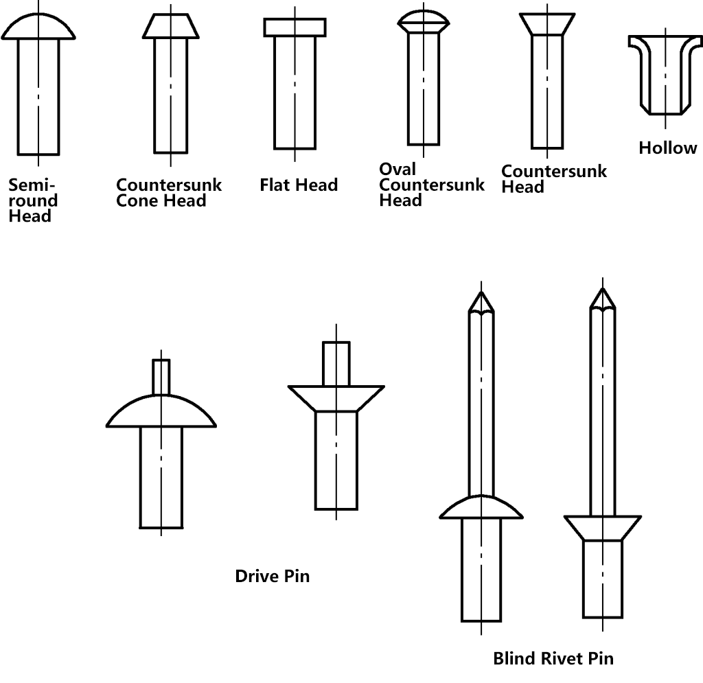
Rivets are usually made of aluminum, but steel and copper rivets are also available. Generally, steel rivets are used for movable riveting and high-strength riveting.
(2) Riveting tools
Common manual riveting tools include hammers, pressure punches, snap tools, and bucking bars. There are also specialized riveting machines nowadays.
1) Pressure punch
As shown in Figure 36a, after the rivet is inserted into the hole, the hammer strikes the pressure punch to press the workpieces tightly together, preventing the situation shown in Figure 36b from occurring.
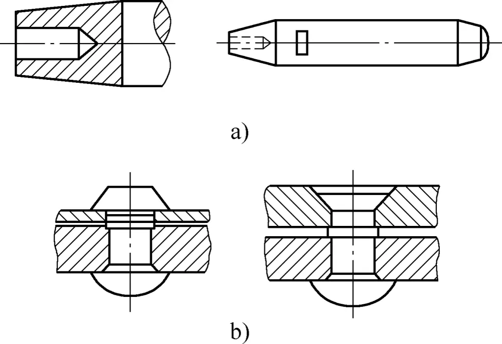
2) Snap tool and bucking bar
As shown in Figure 37, the working parts of both the cap die and the bottom die are concave. The concave shape should be made according to the shape of the rivet head used, generally a concave spherical surface, and hardened and polished. During riveting, the cap die is used to form a complete rivet head, while the bottom die is used to hold the other end of the rivet head to prevent deformation. The shank of the bottom die is made into a flat surface and can be clamped in a bench vise.
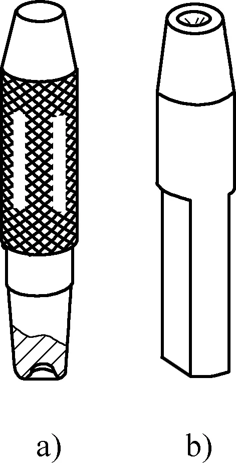
a) Cap die
b) Bottom die
Now, some small and medium-sized parts can be riveted on a riveting machine. The power of the riveting machine is achieved through hydraulics. The force application method of the upper punch is to rotate and press the rivet head around the center of the riveting machine. By installing different punches, various types of rivets can be joined. The riveting quality is more stable and efficient compared to manual riveting.
2. Determination of rivet dimensions and hole diameters
(1) Rivet diameter
The rivet diameter is determined based on the thickness of the workpiece to be riveted, generally taken as 1.8 times the workpiece thickness, then rounded to a standard diameter. It can also be selected according to Table 21.
Table 21 Selection of rivet diameter (unit: mm)
| Calculated thickness of component | 9.5~12.5 | 13.5~18.5 | 9~24 | 24.5~28 | 28.5~31 |
| Rivet diameter | 19 | 22 | 25 | 28 | 31 |
Standard rivet diameters can be selected according to Table 22.
Table 22 Standard rivet diameters (unit: mm)
| Rivet Diameter | Nominal Diameter | 2.0 | 2.5 | 3.0 | 4.0 | 5.0 | 6.0 | 7.0 | 8.0 | 10.0 | 13.0 | 16.0 |
| Tolerance | ±0.1 | +0.2 -0.1 | +0.3 -0.2 | +0.4 -0.2 | ||||||||
(2) Rivet length
To determine the length of the rivet to be used, in addition to considering the thickness of the connected parts, the material left for forming the rivet head must be sufficient to make a complete rivet head. The rivet length can be calculated using the following formula:
- Length of round head rivet shank Lround=S+(1.25~1.5)d
- Length of countersunk rivet Lcountersunk=S+(0.8~1.2)d
- Length of drive pin and blind rivet shank Ldrive=S+(2~3)mm
- Length of drive pin and blind rivet shank Lblind=S+(3~6)mm
Where
- S – Total thickness of riveted parts (mm);
- d – Rivet diameter (mm).
(3) Hole diameter
For fixed riveting, the hole diameter is selected according to Table 23. A smaller hole diameter results in a tighter rivet connection but makes rivet insertion more difficult; a larger hole diameter may cause the workpiece to loosen easily. In practical work, usually drilling a hole with the same size drill bit as the rivet diameter is sufficient.
For movable riveting, the hole diameter should be appropriately enlarged.
Table 23 Standard rivet diameters and hole diameters (unit: mm)
| Nominal diameter | 2 | 2.5 | 3 | 4 | 5 | 6 | 8 | 10 | |
| Hole diameter | Precision fit | 2.1 | 2.6 | 3.1 | 4.1 | 5.2 | 6.2 | 8.2 | 10.3 |
| Rough fit | 2.2 | 2.7 | 3.4 | 4.5 | 5.6 | 6.6 | 8.6 | 11 | |
3. Riveting methods
(1) Round head rivet riveting
Riveting steps: Drill holes in the workpiece (the ideal processing method is to drill holes with the connected workpieces together) → Insert rivet → Hold the bottom end of the rivet with a bottom die, use a pressure punch to make the workpieces fit tightly → Use a hammer to form a rough shape → Use a cap die to form a complete rivet head.
(2) Countersunk rivet riveting
In workpieces, round bars are often used as rivets, requiring two rivet heads to be formed.
The riveting steps are similar to those for round head rivets (the countersink angle is generally 90°). Namely: Insert rivet → Use pressure punch to make workpieces fit tightly → Use hammer to upset the rivet → Form rivet heads at both ends → Flatten the rivet heads.
(3) Hollow rivet riveting
Insert the hollow rivet into the hole, use a discarded center or sample punch to first punch the end of the rivet, causing the rivet hole to expand and fit tightly with the workpiece hole, then use a specially made punch to make the rivet head fit tightly with the workpiece.
(4) Movable riveting
When riveting for movable connections, the hammer impact force should not be too strong. Regularly check the relative rotation of the workpieces. If the riveting is found to be too tight, place one end of the rivet on a pad with a hole, use a hammer to strike the rivet head on the other end a few times, and add some lubricating oil, then rotate the workpieces relative to each other a few times.
(5) Mechanical riveting
Due to the low efficiency and high labor intensity of manual riveting, mechanical riveting methods are often used in mass production. It mainly utilizes mechanized rivet guns and riveting machines for riveting.
XII. Bending and Straightening
1. Bending
(1) Concept of bending
The operation of bending bars, strips, plates, pipes, and various profiles into the required shape is called bending.
For materials to be bent, they must have a certain degree of plasticity.
During the bending process, the material’s shape changes under the action of force, and the material’s properties also change. The material becomes harder and more brittle, a phenomenon known as cold working hardening (for example, if a lead wire is bent back and forth several times, the bent portion of the wire will become harder). The cold working hardening phenomenon of materials can be eliminated through annealing treatment.
(2) Calculation of material length before bending
When bending, if the drawing does not indicate the unfolded length, it needs to be calculated before cutting and bending into shape. During bending, the outer layer of the material stretches, while the inner side is compressed and shortened. The length of the middle layer of the material remains unchanged, and this layer is called the neutral layer. Usually, fitters calculate the material length based on the neutral layer.
Example Suppose there is a flat steel bar 4mm thick and 12mm wide, used to make a multi-right angle workpiece as shown in Figure 38. Calculate the material length L.
Solution L=(2×48)mm+[2×(42-8)+76+(4×4π/4)]mm= (96+68+76+12.56)mm=252.56mm
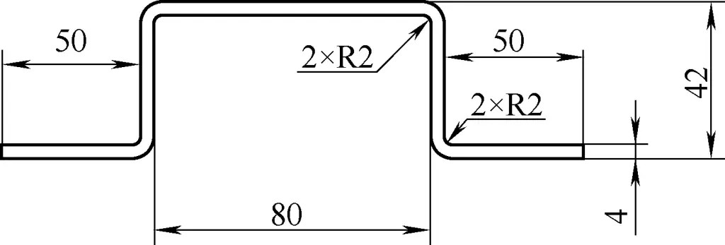
(3) Bending right angles
The method for bending right angles is to first mark the bending line, then clamp the workpiece in a bench vise with the line flush with the vise jaws and both sides perpendicular to the jaws. Use a hammer to strike the base of the workpiece to form a right angle. If the vise jaws are shorter than the workpiece fold line, a right-angle iron can be used as a fixture to hold the workpiece.
For thin sheet materials, a wooden mallet can be used for hammering; for thicker sheet materials with shorter edges to be bent, a hardwood block can be used as a cushion before hammering; if the surface quality requirements of the workpiece are not high, the hammer can be used directly. When hammering, strike near the folding point of the bend, not the upper end of the material. To bend a workpiece as shown in Figure 39, follow these steps:
- Calculate the length of the material (in actual work, for parts with strict dimensional requirements, some allowance can be added and adjusted after bending).
- Mark lines on the sheet material. It’s best to mark from the center of the blank towards both ends, marking the positions of the two middle right angles.
- Place an angle iron pad on the bench vise jaws, clamp the blank correctly according to the lines, and bend the first right angle, as shown in Figure 39a.
- Place forming die 1 against the first right angle and bend the second right angle, as shown in Figure 39b.
- Using the two bent right angles as a reference, mark the positions of the remaining two right angles.
- Place liner 2 into the original two right angles, clamp the workpiece along the marked line, and bend the remaining two right angles, as shown in Figure 39c.
- Shape and remove flash.
(4) Bending arcs
The method for bending arc-shaped workpieces is shown in Figure 40, where the arrows indicate the hammering points. Longer arrows indicate that the hammering force should be greater and the hammering points should be closer together; shorter arrows indicate that the hammering force should be less and the hammering points should be more spaced out.
(5) Bending pipes
When the inner diameter of the pipe is large (greater than 10mm), use the method of filling the pipe with sand, as shown in Figure 41a. Before bending, fill the pipe with dry sand (tap the pipe wall continuously while filling to ensure compactness), and plug both ends with wooden stoppers. If the pipe has a seam, place the seam at the neutral layer position, as shown in Figure 41b.
It’s best to bend pipes using a pipe bending tool. The radius of the arc groove on the turntable and support of the pipe bending tool should be determined by the outer diameter of the pipe being bent, while the size of the turntable should be based on the bending radius. When using, insert the pipe into the arc groove, hook the pipe with the hook, and then operate the handle to bend.
2. Straightening
(1) Concept of straightening
Due to storage, transportation, processing, heat treatment, and other reasons, plate materials, square steel, round steel, and other parts often develop defects such as bending, warping, or twisting. The process of using a hammer or certain machines to eliminate deformation and restore the original state of warped workpieces or materials is called straightening.
(2) Straightening tools
The material to be straightened must have a certain plasticity; brittle materials are not suitable for straightening.
- Flat plates, anvils, V-blocks, etc. Flat plates are used for straightening reference surfaces, anvils are used as bases for hammering materials, and V-blocks are often used for straightening shaft-like parts.
- Hammers, wooden mallets, etc. Hammers are used for general straightening, while wooden mallets are used for straightening machined surfaces, thin parts, and other non-ferrous metal parts.
- Screw pressure straightening machine. The screw pressure straightening machine is used for straightening bar stock and shaft-like parts.
- Inspection tools such as surface plates, try squares, scribing blocks, and dial indicators.
(3) Straightening methods
Commonly used straightening methods include direct reverse bending, stretching, and pressing.
1) Direct reverse bending method
The direct reverse bending method involves straightening the deformed part of the material directly. This method is suitable for straightening bar stock.
For twisted bar stock, use a wrench to restore it directly, as shown in Figure 42. When straightening, clamp the workpiece in a bench vise and use a special wrench to twist the bar stock back to its original shape. For bent bar stock, use the method shown in Figure 43 to straighten the bent part directly.
When using the method shown in Figure 43a, the bench vise must be clamped close to the bent part of the bar stock to prevent multiple bends from occurring. After slightly straightening the bar stock with a wrench, clamp it straight in the vise jaws (Figure 43b), then place it on a flat plate and continue hammering it straight (Figure 43c).
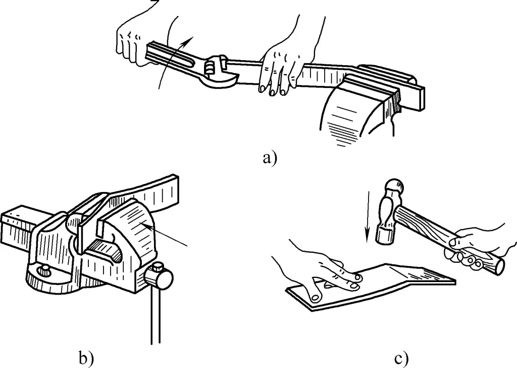
2) Stretching method
The stretching method involves hammering certain parts of the material to elongate and expand the material underneath the hammered area, thus achieving the goal of straightening the deformed part.
3) Pressing method
The pressing method is often used for straightening bent shafts. Thin shafts can be straightened using a manual screw press, while larger diameter shafts use a hydraulic press. Support the shaft on two V-blocks, with the V-blocks not too far apart. Use a dial indicator to find the bent point, then turn the press screw or use the hydraulic press to press on the high point of the shaft. Continue pressing and measuring until it’s straight.
4) Stretching method
Bent thin wire materials can be straightened using the stretching method, as shown in Figure 44. When straightening, clamp one end of the wire in a bench vise, wrap the wire around a round wooden block near the vise jaws, pull the wooden block back with your left hand, and straighten the wire with your right hand by pulling it taut.
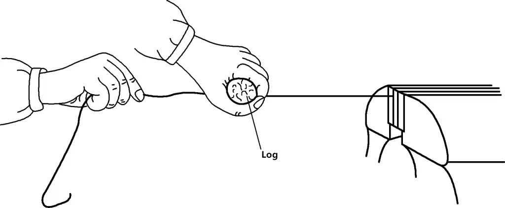
Warped thin metal sheets can be flattened using a wooden mallet. For thinner sheets, you can place the warped metal sheet on a flat plate, press one end of the sheet with your left hand, and use your right hand to hold a flat wooden block against the warped metal sheet, forcefully flattening it outward.

