Grinding Fundamentals: Forces, Heat, and Tool Selection
What makes smooth, precise parts possible? Grinding! This hidden hero of manufacturing creates incredibly accurate finishes. We'll explore how grinding…
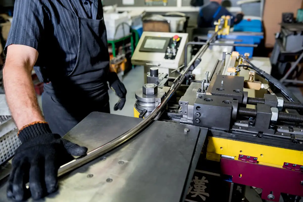
Pipe bending technology has evolved alongside the rise of shipbuilding, petrochemical, and other industries. In recent years, it has seen rapid development in the motorcycle, bicycle, and metal furniture sectors.
In tube bending, the ratio of half the width of the tube in the direction of bending to the bending radius is defined as the curvature.
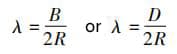
Where:
It is evident that the larger the B or D, and the smaller the R, the greater the curvature.
Tube bending techniques can be categorized by method into rotary bending, push bending, press bending, and roll bending; by temperature into cold bending and hot bending; and by the presence of a mandrel into mandrel bending and freeform bending.
During the bending of tubes, the material on the outer side of the deformation zone undergoes tangential stretching and elongates, while the material on the inner side experiences tangential compression and shortens. The primary manifestations are thinning of the tube material on the outer side due to elongation, and if the elongation exceeds the material’s elongation rate, the tube will rupture.
On the inside, compression leads to excess material; if this excess exceeds the material’s creep capacity, wrinkling occurs on the inner side of the bent tube. To ensure the quality of tube bending, it is essential to control the degree of deformation within an acceptable range.
The bending deformation limit, which is the allowable degree of deformation during tube bending, depends on factors such as the mechanical properties of the material, the structural dimensions of the tube fittings, wall thickness, and the bending process. Table 3-11 lists the minimum bending radius for low carbon steel, assuming the ratio of wall thickness to diameter is greater than 0.1.
Table 3-11: Minimum Bending Radius for Low-Carbon Steel Tubing (t/D ≥ 0.1)
| Bending Methods | Minimum Bending Radius | Bending Methods | Minimum Bending Radius |
| Rotary Bending | (2 to 2.5) x Diameter | Press Bending | ≥16D |
| Press Bending | (2.5 to 3) x Diameter | Roll Bending | 12D |
1) For steel tubes with a high curvature (B/R) and a t/B ratio above 0.2, the push bending method is employed for bending or elbow processing.
2) For workpieces with a small curvature (B/R) and a small central angle of the arc, a press bending method with top and bottom dies can be considered. Press bending typically requires t/B > 0.1.
3) For workpieces with a small curvature (B/R) but a large central angle, bending on a simple tube bender is advisable. The clamping mechanism of a simple tube bender, attached to the mandrel die, is not limited by the length of the rotating arm like a hydraulic tube bender.
4) For workpieces with a large bending radius R but also a large central angle, a three-roll bending machine can be used for forming. The dies are simple and versatile. Ring-shaped workpieces can be bent in multiple rings at once and then cut into individual pieces.
5) For workpieces with a bending radius R of less than 350mm, the winding method on a hydraulic tube bender can be considered. This is because the maximum diameter of the mandrel wheel, including the flange, is ≤800mm, which can be machined on a standard lathe, significantly reducing material costs and, accordingly, the overall cost.
With large production volumes and strong processing capabilities, the bending radius R can be increased to 1000mm. Several domestic manufacturers can now produce automatic tube benders with a bending radius of 1000mm.
6) In the design of rectangular tube bending dies, when 2.5 ≤ R/B ≤ 10, in addition to the winding method, other auxiliary means should be considered, such as protruding the working surface of the mandrel wheel or filling the tube cavity with sand or other fillers.
This is because, in high-curvature bending, methods other than the use of a chain-type mandrel cannot guarantee that the inner and outer diameters of the tube will be full after deformation, and chain-type mandrels are very expensive to process.
7) When selecting bending dies, the ratio of wall thickness t to the width B of the rectangular tube in the bending direction should also be considered. A larger ratio facilitates forming, while a smaller ratio makes forming more difficult.
The above selection methods, except for the second, are based on a t/B ratio of ≥0.05. Figure 3-73 shows the bending effect with a protruding mandrel wheel filled with yellow sand on the left, and without sand on the right. Bending conditions: rectangular tube size 30mm×20mm×1mm, width in the bending direction 20mm, radius of the tube’s centerline after bending 60mm, with the yellow sand’s moisture content at about 1.5%.
Rectangular tubes are typically not used as conduits for fluids but are more commonly employed in the supporting structures of building accessories. Generally, only the outer diameter and the smooth appearance of the two lateral surfaces are required, while deformation on the inner surfaces is not emphasized. This approach allows for measures to prevent wrinkling on the visible surfaces.
The use of a protruding core wheel in the bending model for square and rectangular tubes is an effective means to prevent sidewall wrinkling. Through long-term practice and data accumulation, it has been found that the height of the protrusion can be calculated. The core idea is to convert the amount of compressive deformation inside the midline of the tube into the height of the core protrusion.
The calculation is as follows:
The compressive deformation coefficient inside the midline multiplied by the deformation width inside the midline, minus the material’s creep capability under natural conditions (natural conditions refer to room temperature without any positive or negative pressure) and the comparison value (the comparison value refers to the ratio of the material’s thickness to the deformation diameter under no-pressure-edge conditions, i.e., the material’s inherent creep capability).
The resulting value, multiplied by two, represents the increased length as the compressed edge of the tube transitions from a straight line to a curve.
The equilibrium condition for a wrinkle-free bend in the tube is:
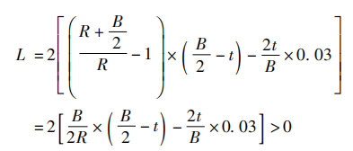
In the formula,
If the calculated value exceeds zero, it is necessary to set up a mandrel protrusion.
At this point, the calculated result can be added to the working line length of the mandrel wheel, turning the straight segment into an arc. If the resulting arc is too high and affects the forming of the walls on both sides of the tube, a good effect can be achieved by notching out (2-4)t from each side wall (see Figure 3-74c).
Through calculation, we know that the value of material creep (2t/B×0.03) is actually quite small. In cases of relatively low thickness, it is sufficient to round off the calculated result appropriately.
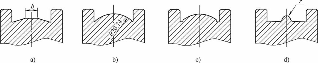
The cross-sectional shape of the mandrel wheel protrusion can be trapezoidal (see Figure 3-74a), arc-shaped (see Figure 3-74b, c), or semi-circular (see Figure 3-74d). These three shapes are suitable for bending workpieces with curvatures ranging from small to large, respectively.
During the prototype phase, utilizing existing flat-bottom core wheels, one can affix steel strips of the appropriate height or round steel bars of the suitable diameter for trial molding. After data collection, modifying the core wheels can achieve significantly increased efficiency. This calculation method is well-suited for rectangular tubes where the external plane serves as the appearance surface.
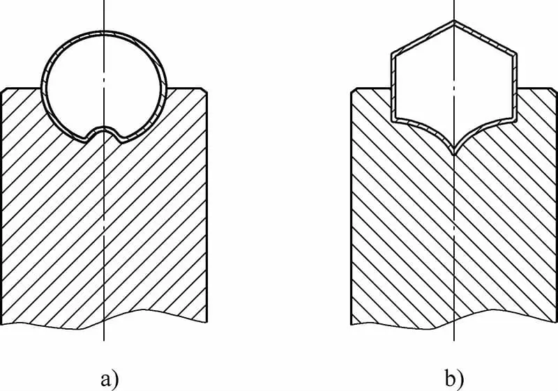
Extending its application to the bending of round and hexagonal tubes, as well as the roll forming of square tubes, is equally meaningful and effective, as shown in Figure 3-75.
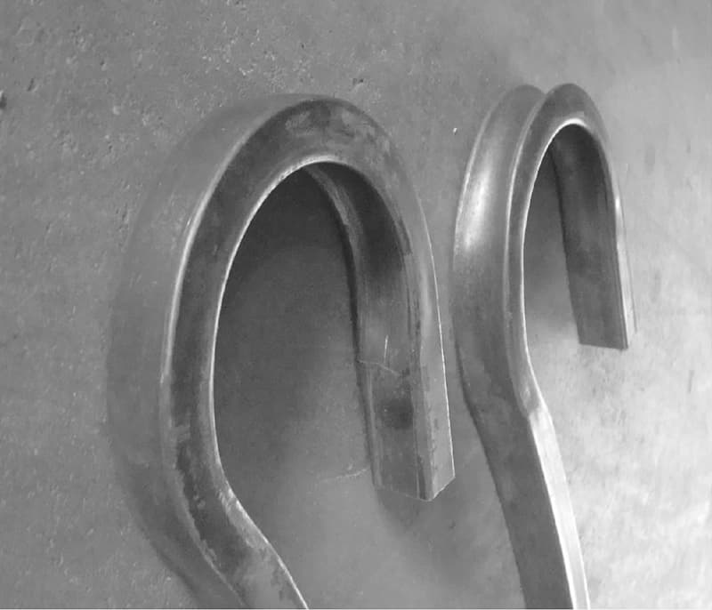
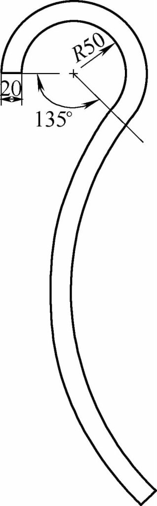
For example, consider a rectangular tube with external dimensions of 20mm x 30mm and a wall thickness of 1mm, bent along the 20mm width to a radius of R=50mm. The semi-finished product after processing is shown in Figure 3-76. Calculate the protruding height in the core wheel.
Given: R = 50mm, B = 20mm, t = 1mm.
Substituting the values into the formula, we obtain
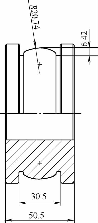
2 × (0.2 × 9 – 0.006) mm = 3.588mm, with a chord height of 6.42mm, as shown in Figure 3-77.
When the relative bending radius of the tube is too small (B/R ≤ 5), the excess material on the inside of the centerline is too abundant to be accommodated by a single curve. In such cases, a dual-curve technique, also known as the double-rib method, is employed to process the mandrel wheel, as shown in Figure 3-78.
The forming conditions depicted in Figure 3-79 are as follows: a central rib made of aluminum alloy tubing, with a material thickness of 1.2mm, a width of 50mm, and a bending direction B of 25mm; the working diameter of the mandrel wheel is 100mm. The tube is filled with sand, which has a moisture content of approximately 1.5%.
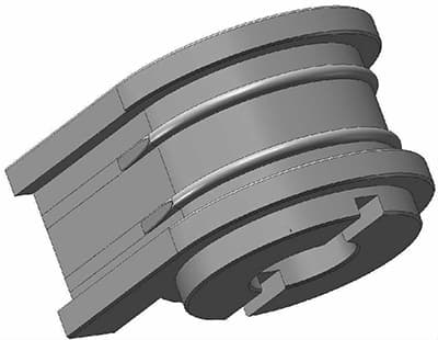
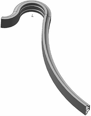
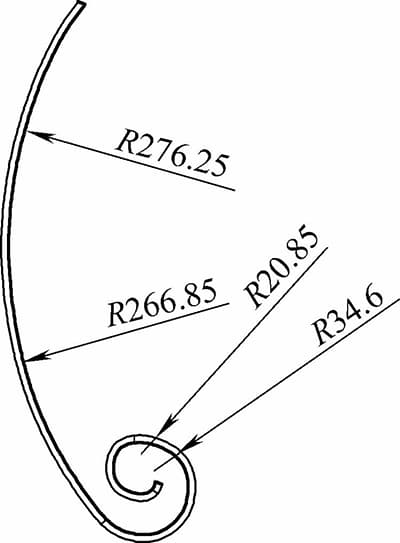
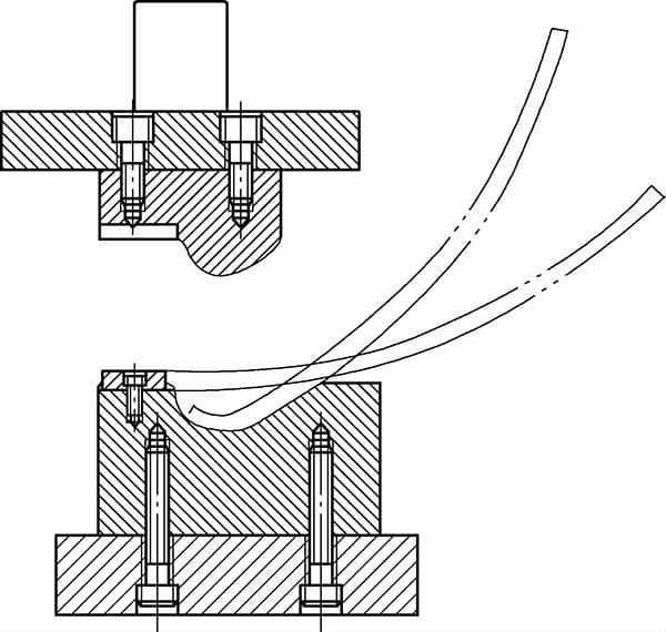
The image in Figure 3-80 depicts a type of fire pit leg made from 40×8×0.8 cold-rolled hollow section tubing. This part is categorized under bending molds due to the rotational movement of the forming mold. After the initial bending process, as shown in Figure 3-81, the material is secured within the gap of mandrel 5 by a cam-type fixture 13 in a manual rolling mold, and the workpiece is shaped by turning handle 12 as illustrated in Figure 3-82.
The advantage of this mold is that it enables forming angles to exceed 360 degrees.
Bending process: Large radius roll bending (three-roll bender) → First bend (mechanical press) → Rolling (manual).
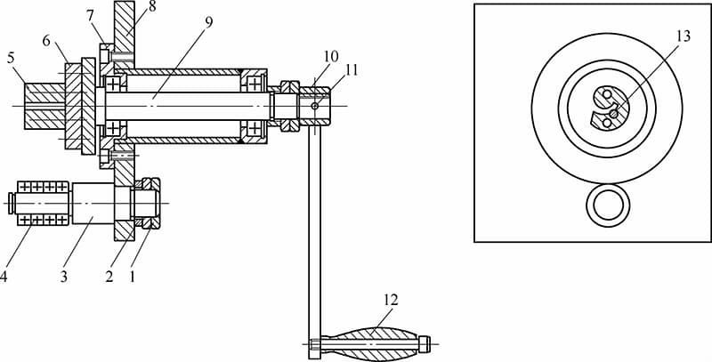
1—Nut 2—Washer 3—Shaft 4—Bearing 5—Die Core 6—Die Core Base 7—Bearing Sleeve 8—Column Stand 9—Main Spindle 10—Force Arm Sleeve 11—Dowel Pin 12—Handle 13—Cam Clamp