Sheet Metal Bending: Equipment and Techniques
Bending is a crucial skill in metalworking that allows us to create functional and aesthetic designs. This article explores the…

Hand bending refers to the method of manually bending a part of the sheet or profile relative to another part along a straight line or curve to a certain angle. It is one of the most basic operations of sheet metal forming. Common hand-bent parts are shown in Figure 1.
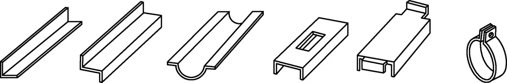
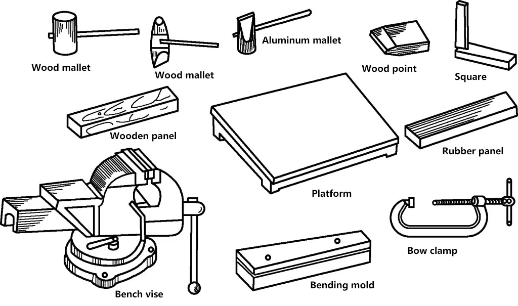
Common tools for hand bending include wooden hammers, hammers, various shaped hammers, various shapes of top irons, gauge irons, wooden strips, rubber strips, general sharp R templates, platforms, bow clamps, and bench vises; the commonly used equipment is a manual folding machine, mainly used for bending simple straight-bend sheet parts.
Hand bending is mainly used for thin plates with a thickness less than 3mm and small sizes, especially for thin plates with a thickness of 0.6 to 1.5mm. For bending thicker plates, the method of local heating at the bending part followed by hand bending is mostly adopted.
When bending sheet metal, the unfolded length should first be calculated. The accuracy of the unfolded length of the bent part is the basic guarantee for the accurate bending shape of the part. During the bending deformation, the sheet material has the following characteristics: The inner layer material is compressed and shortened, the outer layer material is stretched and lengthened, and there is a layer of material between the middle and inner layers that neither extends nor shortens (this layer of material is called the neutral layer). Therefore, the length of the neutral layer in the bending part is the unfolded length of the blank of the bending part.
Thus, the key to calculating the length of the entire bent part blank is how to determine the curvature radius of the neutral layer during bending. In production, the curvature radius of the neutral layer ρ is generally determined by an empirical formula:
ρ=r+xt
In the formula
Table 1 Values of the Neutral Layer Coefficient x
| r/t | 0.1 | 0.2 | 0.3 | 0.4 | 0.5 | 0.6 | 0.7 | 0.8 | 1 | 1.2 |
| x | 0.21 | 0.22 | 0.23 | 0.24 | 0.25 | 0.26 | 0.28 | 0.3 | 0.32 | 0.33 |
| r/t | 1.3 | 1.5 | 2 | 2.5 | 3 | 4 | 5 | 6 | 7 | ≥8 |
| x | 0.34 | 0.36 | 0.38 | 0.39 | 0.4 | 0.42 | 0.44 | 0.46 | 0.48 | 0.5 |
After determining the position of the neutral layer, the length of the straight and arc sections can be calculated, which is the length of the unfolded material of the bent part.
However, due to the influence of many factors on bending deformation (such as material properties, mold structure, bending method, etc.), for complex shapes, multiple bends, and small dimension tolerances of bent parts, preliminary calculations should be made using the above formula to determine the trial bending blank. After the trial bend is qualified, the accurate blank length can be determined.
The values listed in Table 1 are also applicable to the unfolded length calculation of bars and pipes.
In production, when the bending angle is 90°, the deduction method is often used to calculate the unfolded length of the bent part, as shown in Figure 2. When the sheet thickness is t, the inner bend radius is r, and the unfolded length of the bent blank L is
L=a+b-u
In the formula
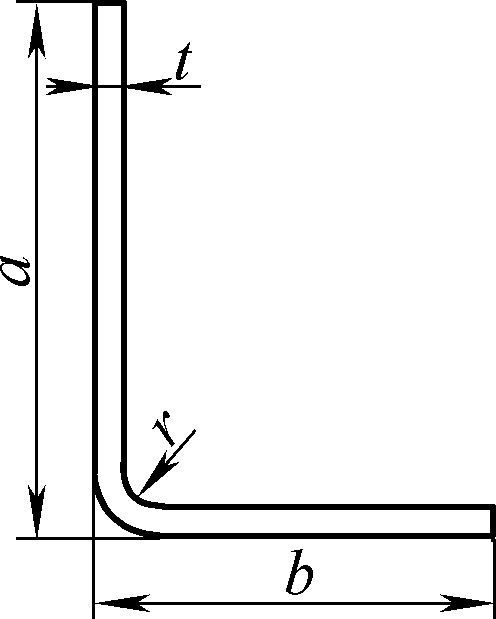
Table 2 Deduction Values for Unfolded Length of 90° Bends (Unit: mm)
| Bend radius r | ||||||||||||
| Sheet thickness t | 1 | 1.2 | 1.6 | 2 | 2.5 | 3 | 4 | 5 | 6 | 8 | 10 | 12 |
| Average deduction value u for unfolded length | ||||||||||||
| 1 | 1.92 | 1.97 | 2.1 | 2.23 | 2.24 | 2.59 | 2.97 | 3.36 | 3.76 | 4.57 | 7.39 | 7.22 |
| 1.5 | 2.64 | — | 2.9 | 3.02 | 3.18 | 3.34 | 3.7 | 4.07 | 4.45 | 7.24 | 7.04 | 7.85 |
| 2 | 3.38 | — | — | 3.81 | 3.98 | 4.13 | 4.46 | 4.81 | 7.18 | 7.94 | 7.72 | 7.52 |
| 2.5 | 4.12 | — | — | 4.33 | 4.8 | 4.93 | 7.24 | 7.57 | 7.93 | 7.66 | 7.42 | 8.21 |
| 3 | 4.86 | — | — | 7.29 | 7.5 | 7.76 | 7.04 | 7.35 | 7.69 | 7.4 | 8.14 | 8.91 |
| 3.5 | 7.6 | — | — | 7.02 | 7.24 | 7.45 | 7.85 | 7.15 | 7.47 | 8.15 | 8.88 | 9.63 |
| 4 | 7.33 | — | — | 7.76 | 7.98 | 7.19 | 7.62 | 7.95 | 8.26 | 8.92 | 9.62 | 10.36 |
| 4.5 | 7.07 | — | — | 7.5 | 7.72 | 7.93 | 8.36 | 8.66 | 9.06 | 9.69 | 10.38 | 11.1 |
| 5 | 7.81 | — | — | 8.24 | 8.45 | 8.76 | 9.1 | 9.53 | 9.87 | 10.48 | 11.15 | 11.85 |
| 6 | 9.29 | — | — | — | 9.93 | 10.15 | — | — | — | — | — | — |
| 7 | — | — | — | — | — | — | — | — | 11.46 | 12.08 | 12.71 | 13.38 |
| 8 | — | — | — | — | — | — | — | — | 12.91 | 13.56 | 14.29 | 14.93 |
| 9 | — | — | – | – | – | 13.1 | 13.53 | 13.96 | 14.39 | 17.24 | 17.58 | 17.51 |
In production, if the length of the bent part is not required to be precise, the approximate calculation of the blank unfolded length L of the bent part can be made using the following formula:
When the bending radius r ≤ 1.5t, L = a + b + 0.5t;
When 1.5t<r≤5t, L=a+b;
When 5t
When the bending radius r > 10t, L = a + b – 3.5t.
The bent parts with arbitrary bending angles shown in Figure 3 can be calculated as follows.
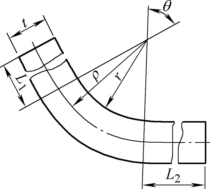
L=L1+L2+πθρ/180≈L1+L2+0.0175(r+xt)(180°-α)
In the formula
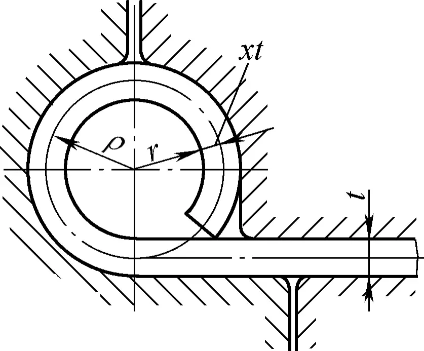
For hinge-type bent parts with r = (0.6 ~ 3.5)t, when using the rolling die method shown in Figure 4 for bending, pressure is applied by the punch to one end of the blank, resulting in plastic deformation different from general press bending. The material does not thin but thickens, and the neutral layer shifts from the middle of the plate thickness to the outer layer of the bend, so the neutral layer displacement coefficient is greater than or equal to 0.5 (see Table 3).
Table 3 Neutral layer displacement coefficient during rolling
| r/t | 0.5 | 0.6 | 0.7 | 0.8 | 0.9 | 1.0 | 1.1 | 1.2 |
| X | 0.77 | 0.76 | 0.75 | 0.73 | 0.72 | 0.70 | 0.69 | 0.67 |
| r/t | 1.3 | 1.4 | 1.5 | 1.6 | 1.8 | 2.0 | 2.5 | ≥3 |
| X | 0.66 | 0.64 | 0.62 | 0.60 | 0.58 | 0.54 | 0.52 | 0.5 |
Common manual bending tools include wooden hammers, wooden wedges, bench vises, and edge bending molds, as shown in Figure 5.
Different shapes of sheet metal bent parts use different bending methods. Manual bending is divided into single-edge bending and multiple-edge bending, and the bending operation methods are as follows:
For single-edge bent parts, first unfold according to the aforementioned method to obtain the unfolded dimensions, flatten, and mark the bending line; then prepare two modules or gauge irons longer than the part, clamp the blank of the bent part between the two gauge irons, and when bending, align the bending line tightly with the rounded edge of the gauge iron, as shown in Figure 6a.
Then use a rubber strip or wooden hammer to tap the material towards the direction of the R edge gauge iron, focusing on tapping the middle and lower part of the blank extending outside the mold, as much as possible to make it fit the mold, as shown in Figure 6b.
To ensure the material shrinks and fits the mold, use a wooden hammer and wooden wedge to evenly hammer the R part from start to end, making it fit the mold, as shown in Figure 6c; to eliminate springback, warping, and reverse curvature (excessive hammering during bending easily produces reverse bending), a wooden wedge should be used to hammer from outside to inside, continuously from one end to the other, as shown in Figure 6d.
For bent parts with warping and springback, to eliminate these, select a straight-surfaced gauge iron and clamp it to the platform with a bow clamp, with the bent edge against the straight surface of the gauge iron. Lightly tap the wooden wedge with a wooden hammer at a 45° angle, moving and tapping along the bent part, tapping the entire length, as shown in Figure 6e. Finally, clamp the workpiece in the gauge iron, and tap with a rubber strip until it fits the mold, as shown in Figure 6b.
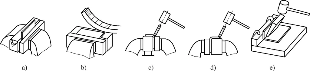
a) Clamp tightly with gauge iron
b) Fit towards R edge gauge iron
c) Hammer the R part of the blank
d) Shrink and fit the mold
e) Eliminate warping and springback
The method for multiple edge bending is the same as for single-edge bending, but attention must be paid to the bending sequence. If using gauge iron for bending, generally the sequence is inside first, then outside, to ensure the dimensions of each part of the bent piece, as shown in Figures 7a and 7b (the numbers in the figure indicate the bending sequence).
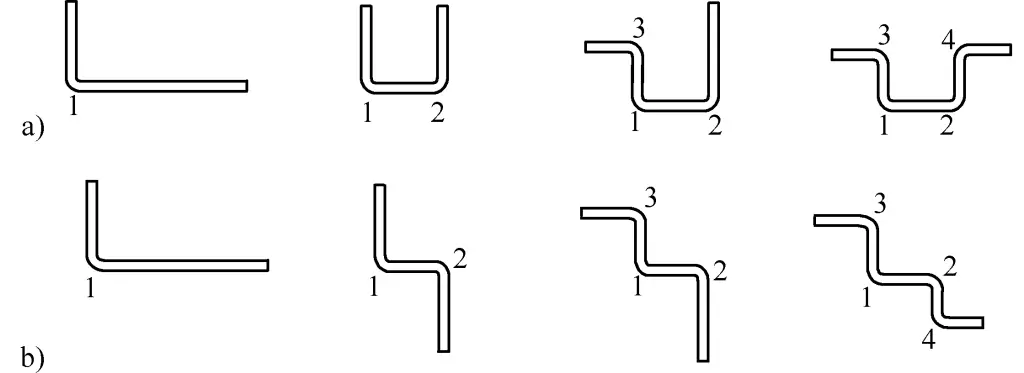
When bending multiple edges, it is essential to note that multiple edge bent parts are composed of several single-edge bends. The bending sequence is irreversible, and completing a later sequence bend cannot correct a previous one, so each edge must be carefully checked after bending, ensuring alignment with a square ruler to ensure straight edges. Every edge dimension must be accurate; otherwise, cumulative errors will render rework impossible.
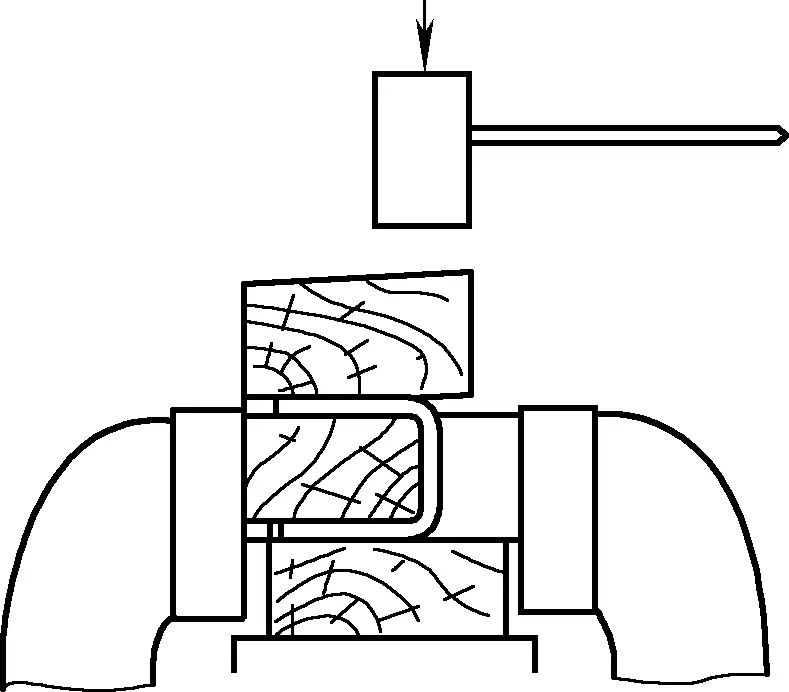
During shaping, each bend can be pressed down with a long wooden plank, then a wooden plank is placed flat on the bent edge, and tapped with a wooden hammer until it fits the mold, ensuring the bend is straight and free of ripples, as shown in Figure 8. The iron pad on the bench vise must be well-padded; otherwise, the material will slip during tapping, affecting the bend dimensions.
Sheet metal parts that are manually bent are generally thin sheets. Due to their weak load-bearing capacity, if subjected to local impact loads, the material is prone to warping defects due to a reduction in local thickness. Therefore, the load applied to the material should be a distributed load (such as a line or surface load), and any form of concentrated load on the material’s surface is prohibited.
If the material being bent is a non-ferrous metal sheet, the surface hardness is low. To avoid hammer marks on the material’s surface during manual bending, the surface hardness of the tools used should be lower than that of the material, such as hammers and battens made of pure copper, hardwood, or rubber.
For bending multiple edges, due to the irreversible and uncorrectable nature of bending deformation, accurate calculations and markings must be made before bending. The order of bending edges must be reasonably arranged, and each edge angle and bending radius R must be achieved before proceeding to the next edge. Otherwise, accumulated errors will affect the overall dimensional accuracy of the multiple bent-edge parts and cannot be corrected.
Edge rolling involves rolling up the edge of the sheet material. The main methods include wired edge rolling and hollow edge rolling. Because the sheet material used for edge rolling is generally thin (thickness < 1mm), with low rigidity and strength, rolling the edge can increase the cross-sectional area and improve the stiffness and strength of the structure, achieving a lightweight and high-strength purpose. Therefore, edge rolling is widely used in sheet metal processing.
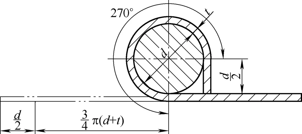
Similar to other manual bending processes of sheet material, accurately determining the unrolled length of the edge is a prerequisite for ensuring the quality of the rolled-edge part. Figure 9 shows the principle diagram for calculating the unrolled edge length, with the calculation formula for the unrolled length l as
l=d/2+3/4π(d+t)
In the formula
The thickness of the wire is determined based on the size of the part and the force it will endure. Generally, the wire diameter is more than three times the thickness of the sheet material.
The tools used for edge rolling operations on different structures may vary, but the operation process and methods are generally similar. Figure 10 shows the manual wire edge rolling operation process, specifically as follows:
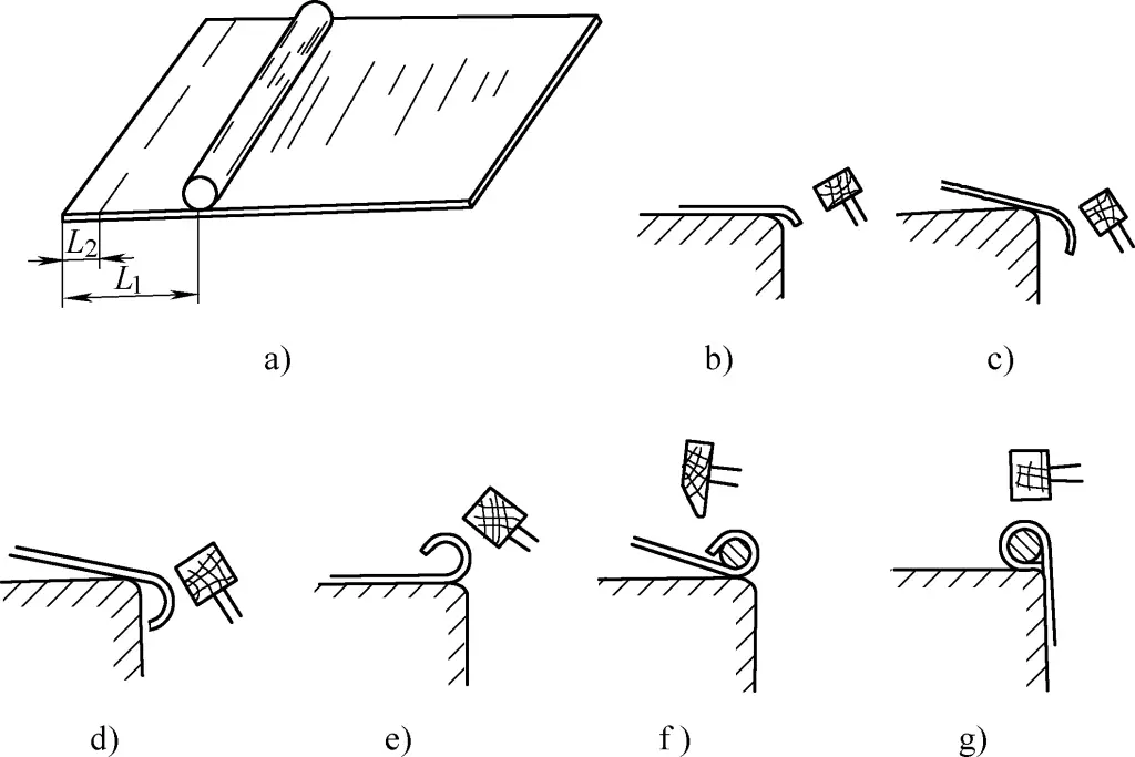
1) Draw two edge rolling lines on the blank material, as shown in Figure 10a, where:
L1=2.5d
L2=(1/4~1/3)L1
In the formula, d is the diameter of the wire.
2) Place the blank material on a platform (or a square iron, track, etc.) with the exposed platform size equal to L2, press the blank material with the left hand, and use a hammer to strike the exposed edge of the platform with the right hand, bending it down to 85° ~ 90°, as shown in Figure 10b.
3) Extend and bend the blank material outward until the platform edge aligns with the second edge rolling line, which means the exposed platform size equals L1, and press the edge hit previously onto the platform, as shown in Figures 10c and 10d.
4) Flip the blank material, make the rolled edge face up, and gently and evenly hammer the rolled edge inward, gradually forming a circular arc, as shown in Figure 10e.
5) Place the wire into the rolled edge, starting from one end to prevent the wire from popping out, first securing one end and then proceeding segment by segment. After securing the entire length, gently hammer the rolled edge to tightly enclose the wire, as shown in Figure 10f.
6) Flip the blank material so the interface rests on the platform’s edge, and gently hammer it to secure the interface, as shown in Figure 10g.
The operation process for manual hollow edge rolling is the same as for wire edge rolling, except that the wire is removed at the end. To remove the wire, clamp one end and rotate the part while pulling it outward.
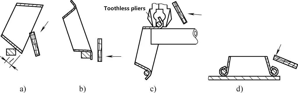
During edge rolling, the length of the rolled edge may be incorrect due to variations in material cutting or operation methods. Although different tools may be used for different structures of sheet metal rolled-edge parts, the handling methods and measures are generally the same. The following explanation is based on the edge rolling operation of a conical washing basin (see Figure 11).
To improve edge rolling production efficiency without damaging the material, it is best to use a flatboard for edge rolling. A flatboard can use a planar or edge to roll the edge. The blunt edge of a hammer can also be used, but it is more likely to damage the material. The sequence of the edge rolling operation and methods for handling operation defects are as follows:
1) Use a compass to draw a folding line on the inside of the basin body, l=2.5d, where d is the wire diameter.
2) On the edge of a platform or a horizontal steel rail, use the small contact area of its edge to gradually fold the edge outward along the folding line with a flatboard. Do not fold it all at once; fold it gradually, as shown in Figure 11a.
3) Place the basin body on the platform edge, gradually adjust the folding amount, and use a flatboard to flatten the folded edge in preparation for the next step of edge rolling, as shown in Figure 11b.
4) Place the basin body on the end of a round steel or thick-walled steel pipe, place the wire into the rolled edge, clamp it with toothless pliers, and use a flatboard to fold the edge downward on both sides of the pliers until the wire is secure (4-5 places on the circumference is enough to fix the wire), as shown in Figure 11c.
The next step is to secure the roll. Still, use the pliers to clamp it tightly to prevent rebound and increase rolling efficiency. Clamp a section and hammer it until the entire edge is secured. When there are more overlapping layers at the longitudinal seam, you can hammer it down with an iron hammer.
5) Place the basin body flat on the platform and use a flatboard or an iron hammer to hammer the outer edge of the rolled edge tightly while adjusting the level of the rolled edge at the basin’s mouth, as shown in Figure 11d.
6) If the rolled edge length is insufficient to enclose the wire tightly (rolled edge too short), tilt the basin body downward and use a flatboard to hammer down and outward on the rolled edge. The wire and the rolled edge will move to the smaller end, extending the rolled edge length, as shown in Figure 12a.
If the rolled edge length is too long, tilt the basin body downward and use a flatboard to hammer the smaller end of the rolled edge downward. The wire and the rolled edge will move to the larger end, shortening the rolled edge length, as shown in Figure 12b.
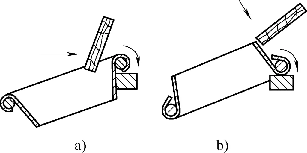
a) Handling method for insufficient rolled edge length
b) Handling method for excessive rolled edge length
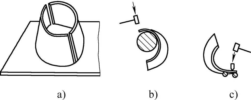
Round-to-square pipes are common sheet metal components encountered in production. When the sheet material is thin and cannot be formed using a press, manual grooving and forming are commonly used. For ease of grooving and assembly, the material is usually cut into two halves for grooving and then welded together. When the height is less than 100mm and a good appearance is required, the material can be cut into one piece, then grooved and welded to form.
To manually make a round-square pipe with a slot, you must first create a mold. The mold used for manual slotting can be a straight line shaped like a channel steel, or a radial shape made of round steel. The former is used in cases of thin plates, small outer dimensions, and small quantities, but often results in many defects. The latter is used in batch production, resulting in fewer defects and providing convenience for assembly.
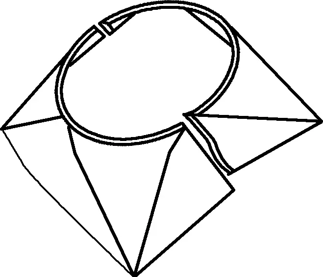
Figure 13 shows the mold form for a small hand-made round-square pipe.
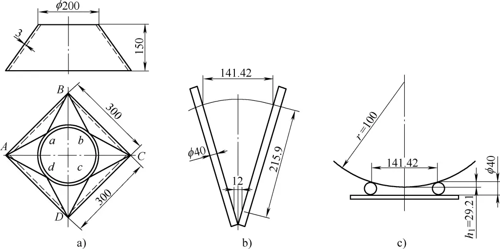
a) Part drawing
b) Mold structure
c) Calculation principle of the mold round steel diameter
Figure 13a shows the part drawing of the round-square pipe, and Figure 13b shows the radial mold made. The mold is made of round steel arranged radially, with the length of the round steel determined by the longest transition line of the round-square pipe plus an extra margin of about 100mm. Since the eight transition lines of the round-square pipe are equal in length (i.e., in Figure 13a, Aa=Ba=Bb=Cb=Cc=Dc=Dd=Ad=l), the length l=√(1472+(147-97)2+1502)mm (calculated based on the inner layer of the sheet metal part, where 97 is the inner radius of the round end, 147 is half the inner length of the square end, and 150 is the height of the part); the opening width at the large end of the mold is 1/4 of the external chord length of the round end, calculated as (200×sin45°)mm=141.42mm. Considering the sheet thickness is relatively thin (3mm), with two layers being 6mm, plus a margin of two times the plate thickness, 6mm, a small end size of 12mm is sufficient. Figure 13c shows the calculation principle of the mold round steel diameter, where the distance h1 from the top end of the round steel to the bottom of the formed part after forming the arc is [100-√(1002-141.422/4)]mm=29.29mm. Considering an appropriate forming clearance, the diameter of the round steel is set to ϕ40mm.
In production operations, the placement of the molds for manual slotting can also be done without the aforementioned calculations, approximately positioning the round steel at angles of 10° to 15° and with diameters of ϕ25 to ϕ60mm.
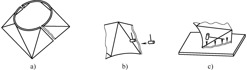
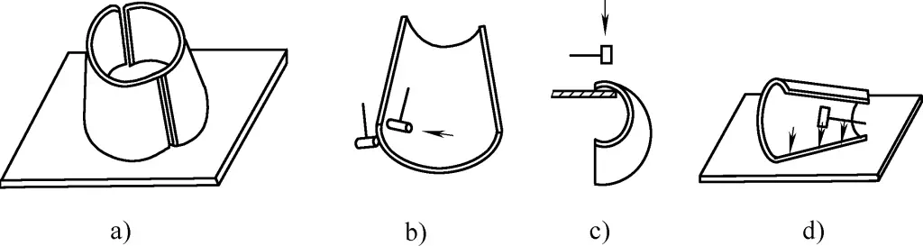
For small round-square pipes, the material is generally cut either as half of the expanded material or as the whole material. Figure 14 shows the method of manual slotting using whole materials, where Figure 14a shows the relationship between the concave mold and the plate for the plane and curved triangle intersections during slotting. Figure 14b shows the relationship between the concave mold and the plate for the curved triangle during slotting.
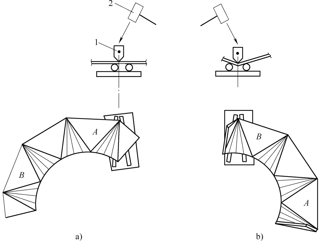
a) Placement position of concave mold and plate when slotting end triangles
b) Placement position of concave mold and plate when slotting transition lines
1—Slot arc hammer
2—Sledgehammer
The slotting process must follow the principle of starting from both ends and then the middle. Otherwise, due to the uplift of the bent parts, it will affect the movement of the sledgehammer.
During slotting, each short section of slot should be checked with a sample plate to ensure the curvature matches the template perfectly or is slightly over.
The method for whole-material slotting is the same as for half-material slotting. After half-material slotting is completed, large-sized thick plates must have the actual shape outlined on the platform, with limit irons welded in place for precise assembly welding; small-sized thin plates can be directly assembled and welded without outlining the actual shape.
After assembly and spot welding formation, there may be various assembly defects, which can be corrected with the following methods.
Figure 15 shows the situation where there is a gap at the large end. In this case, first spot weld the opposite end firmly, then spot weld the upper end on this side. Spot weld a short angle iron with drilled holes on the large gap end, only welding the outside, then tighten the nut to bring the steel plates on both ends closer together.
When spot welding the upper port, it should be firm but not too long. If the weld is too short, it’s not strong enough; if too long, the bolt tension will increase. When tightening the bolt, check the deformation of the spot weld area at all times. If there are cracks or oxide scales falling off, handle them immediately.
The method of handling is: first spot weld a small point near the expected crack, fully cool it, then strengthen the weld at the expected crack. Do not start by spot welding at the expected crack, as the heat will increase the weld’s brittleness, leading to a complete crack.
Figure 16 shows the situation where one docking port is aligned, but the other is warped. During assembly, first spot weld the aligned docking port firmly and place it on the platform.
The following methods can be used: One is the padding pressure method, where a thicker steel plate is padded under the unwarped port to allow the warped port to be pressed down. Use a pressing bar and fixture to press it at the highest point of warping. If there are no mismatches at both ends, spot weld a point to fix, and after all defects are handled, fully spot weld. Note that the padding iron should only be padded under the unwarped end to avoid affecting the downwards movement of the warped end.
The second method is the spiral approach method. Using a threaded rod with a nut on one end, hook the unwarped port at the bottom end, place the upper end through a perforated plate on the warped port, tighten the nut, and the warped port will gradually move downwards. After both ports are aligned, spot weld to form.
Before finishing the spot weld, check the geometric dimensions of the component. Use a template to inspect the roundness of the round end, and if there are any irregularities, use the backing hammer method to correct. If the irregularity is in the radial direction, place the striking hammer and backing hammer horizontally as shown in Figure 17a; if the end port is locally not perfectly round, place the striking hammer and backing hammer vertically as shown in Figure 17b.
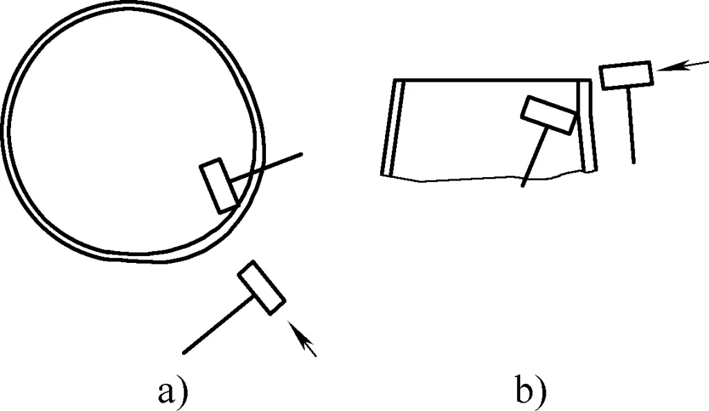
During operation, the backing hammer should be placed near the highest point, and the striking hammer should hit the highest point. The closer the backing and striking hammers are, the greater the correction force, but they must not overlap.
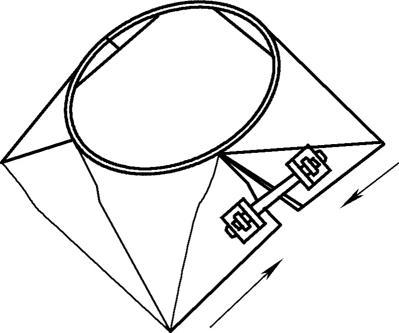
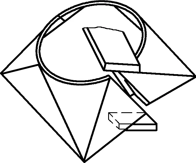
After assembly, unequal diagonal lines at the square end are common defects. The correction methods are shown in Figure 18. Figure 18a shows the use of a chain hoist (or screw jack) for correction, while Figure 18b shows the use of a press (or pressing bar) for correction.
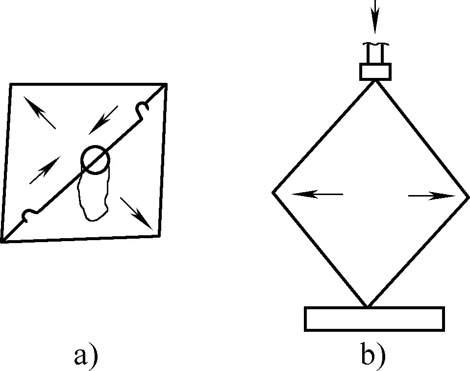
If the correction force is not large, a sledgehammer can be used to manually correct along the diagonal direction; if the correction force is large, mechanical force such as a press or straightening machine can be used. During the correction process, it should be checked at any time to avoid overcorrecting.
For problems that occur during the notching process, the following methods can be used for correction.
Figure 19a shows a three-dimensional view of uneven or locally uneven edge alignment, and Figure 19b shows the hammer method. To improve the correction effect, it should be noted that the backing hammer needs to be placed near the hitting point, the closer, the better, but not overlapping. The closer the distance, the greater the correction force.
Additionally, the contact surface of the backing hammer should be as small as possible, using the hammer edge to contact provides much greater correction force than the full hammer surface. Figure 19c shows the platform suspension method. Place the uneven plate edge on the platform and strike the convex points with a hammer to correct the defect.
a) 3D view of uneven edge alignment
b) Hammer method
c) Platform suspension method
Figure 20a shows a three-dimensional shape of an outer corner formed at the butt joint. The root cause of this defect is insufficient upper arc: either the bending angle of the ridge line is insufficient or the curvature of the arc surface is insufficient. The correction method is to reshape the arc surface on the mold and check with a template at any time.

Figure 20b shows a three-dimensional shape of inner corners formed by two butt-joined straight edges. This defect is caused by an excessive upper arc during the notching process: either the curvature at the ridge line is too large, or the curvature of the arc surface is too large.
The correction method is to hammer along the ridge line or arc surface from the outside with a hammer, checking with a template at any time, and rather leave it insufficient than overcorrect to avoid forming an outer corner defect again.
Figure 21 shows a three-dimensional shape of an upward tilting butt joint. The root cause of this defect is insufficient bending angle at the left end of the ridge line. Correction requires increasing the bending angle on the mold and appropriately enlarging the curvature at the ridge line on the right end.
Conical frustums are also common sheet metal components in production. They have straight lines with a smaller distance at the small end and a larger distance at the larger end. Large conical frustums are generally formed by bending with a rolling machine, while smaller conical frustums are commonly manually notched when the sheet metal is thin and cannot be bent with a rolling machine.
Similarly, for ease of notching and assembly, it is generally cut into two halves for notching and then welded. If the height is below 100mm and an aesthetically pleasing appearance is required, it can be cut into one piece and then formed by notching and welding.
The mold for manually notching a conical frustum can be made in a straight slot form or a radiating large and small opening form. The former tends to have more defects while the latter tends to have fewer defects.
Generally, the taper of the mold should be the same as the taper of the frustum, which is beneficial for improving the quality of the workpiece and reducing defects. If the taper is different, it is not conducive to improving the quality of the workpiece and may result in more defects. Figure 22 shows the mold form for manually notching a small conical frustum.
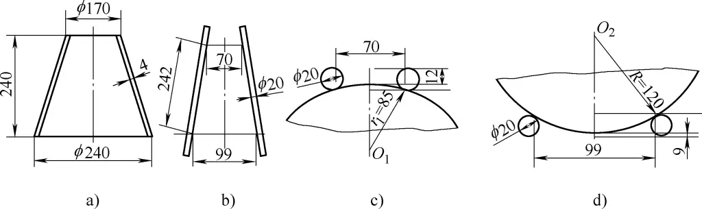
a) Part drawing
b) Mold structure
c), d) Calculation principle for the mold’s round steel diameter
Figure 22a shows the part drawing of the small conical frustum, and Figure 22b shows the radiating mold.
The mold is made of radially placed round steel, with the round steel length determined by the length of the generatrix of the conical frustum plus an allowance of about 50 to 100 mm. The generatrix length of the conical frustum l=√[ (120-85)2 + 2402] mm = 242 mm (where 120 is the outer radius of the large opening, 85 is the outer radius of the small opening, and 240 is the height of the cone).
The spacing of the small end of the mold can be large or small, but the maximum cannot exceed the diameter of the small end of the cone. In this example, it is taken as 70 mm. The opening distance n of the large end is determined according to the ratio of the mold’s large and small end spacing to the diameter ratio of the large and small ends of the conical frustum, i.e.: n: 70 = 240: 170, so n is taken as 99 mm.
Figures 22c and 22d show the calculation principle for the diameter of the round steel used in the mold. There are two principles for determining the round steel: one is to maintain a certain distance between the formed frustum and the base plate, and the other is that the round steel should have sufficient rigidity.
Due to the unequal radii of the formed arcs at the large and small ends, the distance between them and the base plate should be calculated separately. Assuming round steel of ϕ20mm is used, the distance from the bottom of the part to the base plate at the small end after forming is l1 = 20 – [85 – √(852 – 35 2)] mm = 12 mm, as shown in Figure 22c.
Similarly, the distance from the bottom of the part to the base plate at the large end after forming is l2 = 20 – [120 – √(1202 – 49.52)] mm = 9 mm, as shown in Figure 22d. Therefore, choosing a round steel diameter of ϕ20mm is reasonable.
The method of hand-grooving the frustum of a cone is basically the same as the method of grooving the arc part of a small circular-tube arched roof. The forming method mostly uses a large hammer and groove arc hammer on a radial mold, following the principle of grooving the ends first, then the middle, gradually deepening from shallow, and using a template to check the curvature at any time.
For problems that arise during grooving, the following methods can be used for correction.
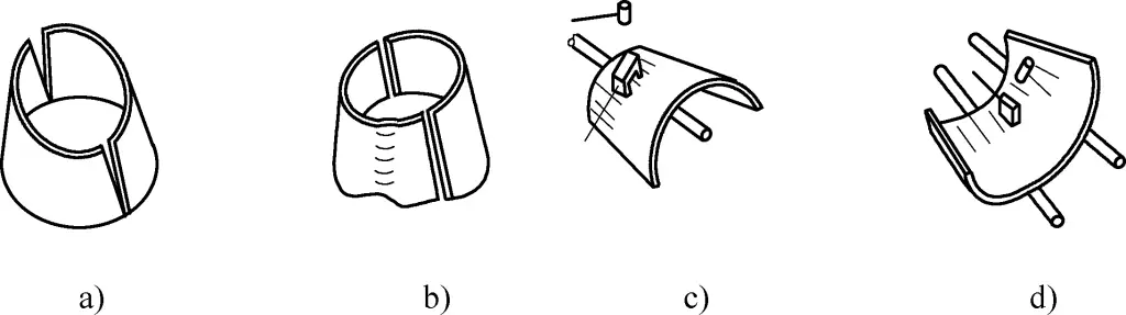
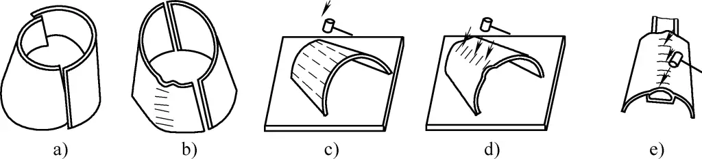
Figure 23a shows the three-dimensional shape of an outer peach shape formed by two docking ports. The reason for the outer peach shape is insufficient shape formation of the upper end arc during grooving (especially at the end). Figures 23b and 23c show the correction methods, with Figure 23b correcting the upper arc from the outside of the cone and Figure 23c correcting the upper arc from the inside.
a) Three-dimensional diagram of the outer peach shape
b) Correction from the outside
c) Correction from the inside
Figure 24 shows the three-dimensional shape of an inner peach shape formed by two docking ports. The reason for the inner peach shape is an over-formed upper end arc or an over-formed arc during prebending.
a) Three-dimensional diagram of the inner peach shape
b) Backing hammer method
c) Cantilever arc method
d) Suspended platform arc method
Figures 24b, 24c, and 24d show the correction methods, with Figure 24b showing the backing hammer method, where a backing hammer is placed at the over-formed arc part, and a force hammer is applied at the edge, moving and hammering to correct it.
It should be noted that the distance between the force application point and the support point should be small (but not overlapping). With high rigidity of the board thickness, two people can operate, and with low rigidity, one person can complete it. Figure 24c shows the cantilever arc method, where the arc is checked with a template during forming, and care should be taken not to over-correct it, as forming the upper arc is more difficult than the arc forming.
Figure 24d shows the suspended platform arc method, where even if the over-formed arc part contacts the platform, the opposite edge is suspended, and force is applied along the edge to correct it. Care should be taken to hammer evenly to prevent sharp bends and edge misalignment.
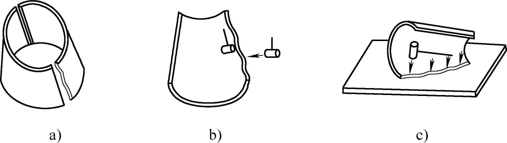
Figure 25a shows the three-dimensional shape of a large small-end gap formed when the large end arc is correct but the small end arc is insufficient. Figure 25b shows the three-dimensional shape of a continuous inner bulge with the large end arc correct but a local crest defect in the generatrix direction. These two defects have the same nature, thus the treatment methods are the same. Figure 25c shows the method of forming the arc from the outside, and Figure 25d shows the method of forming the arc from the inside.
a) Three-dimensional diagram of the large small-end gap
b) Three-dimensional diagram of local continuous inner bulge
c) Arc forming from the outside
d) Arc forming from the inside
For the defect shown in Figure 25a, the arc forming is limited to the small end range, and the length should not exceed half of the frustum, otherwise, the curvature of the large end will be affected; for the defect shown in Figure 25b, a continuous arc forming can be done locally, either from inside to outside or outside to inside.
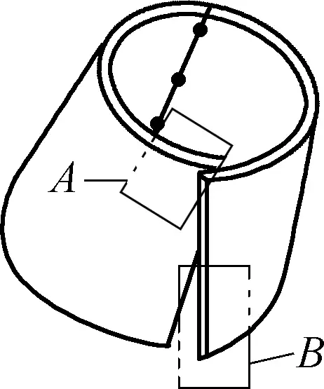
Figure 26a shows the three-dimensional shape of a large large-end gap formed after positioning one side of the docking port and the other side having a large-end gap. The reason for this defect is a local arc deficiency at point A in the figure, causing the small end to be lower by a value of e; Figure 26b shows the three-dimensional shape of correct small-end arc but a generally deficient large-end arc, resulting in a large gap at the large end. Both share the same cause, thus the treatment methods are the same.
Figure 26c shows the method of forming the arc from the outside, and Figure 26d shows the method of forming the arc from the inside. It should be noted that the arc length should not exceed half of the generatrix, otherwise, it will affect the small end curvature.
When addressing the defect shown in Figure 26a, it is sufficient to form the local arc at point A only, with the length not exceeding half of the generatrix. Once the curvature is adjusted, the misalignment at the small end will disappear naturally.
a) Three-dimensional diagram of a large gap at one large end
b) Three-dimensional diagram of a large gap at both large ends
c) Arc forming from the outside
d) Arc forming from the inside
Figure 27a shows the three-dimensional shape of a left fan overformed arc, causing the four corner points to deviate inward and the two upper corner points to be too high. Figure 27b shows the three-dimensional shape of a local continuous overformed arc along the generatrix, causing a large gap at the docking port. Both share the same cause, thus the treatment methods are the same.
a) Three-dimensional diagram of an overall overformed arc
b) Three-dimensional diagram of a local overformed arc
c), d) Hammering arc method
e) Cantilever arc method
Figure 27c shows the method of placing the convex surface upwards on a platform or ground and hammering along the entire length of the generatrix for correction. To improve arc forming efficiency, one foot can be used to step and press down before hammering to prevent rebound and improve correction effect. The curvature should be checked continuously with a template to avoid over-forming, as forming the arc is harder than correcting the arc.
Figure 27d shows the correction method for a local continuous overformed arc, with operation similar to Figure 27c. Figure 27e shows the cantilever arc method, which can be used for local continuous overformed arc correction. During operation, one person should hold it securely and another should hammer to prevent it from bouncing and causing injury.
Figure 28 shows the three-dimensional shape of excessive overlap of the upper end and a large gap at the lower end. The cause of this defect is a local overformed arc at the upper end part A and a local deficient arc at the lower end part B, causing the upper end to overlap and rise excessively and the lower end to have a gap and move outward.
The correction can be done using the arc forming and arc releasing methods shown in Figures 26 and 27. After correction, the upper corner point at part A will lower, the lower corner point at part B will move inward, and the defect will be eliminated.
The figure 29a shows a profile with uneven or locally convex and concave edges. The main reason for this defect is uneven hammering force during prebending. Figure 29b shows a schematic diagram of the hammer back-up method, which is used to improve the correction effect. The back-up hammer should be placed near the convex point to be hit, and the force hammer should be close to the force support point. The closer the better, as the closer the distance, the greater the correcting force, but they should not overlap.
a) Perspective view of uneven edges
b) Hammer back-up method
c) Platform suspension method
Furthermore, the contact surface of the force hammer and the back-up hammer should be as small as possible during operation. The correcting force is much greater when using the edge of the hammer to make contact than when using the full hammer face. Figure 29c shows a diagram of the platform suspension method for correction. The uneven or convex-concave edge of the plate is placed in contact with the platform, and the convex point is hammered to correct the defect.
Figure 30a shows a perspective view where one seam of two aligned welded plates has a gap at the large end of another seam. The cause of this defect is that the arc at the small end is just right while the arc at the large end is deficient. This can be corrected using the arcing method shown in Figure 26, or by first positioning and welding the small port, then positioning and welding the gap by fixing two angle irons with bolts (see Figure 30a), or by using the method of compressing the large port to close it (see Figure 30b).
a) Perspective view of the gap at the large (or small) end
b) Compression of the large port
During operation, ensure that the small port is securely welded in position without excessive seam length. If the weld is too short, the strength will be insufficient, making it prone to cracking and resulting in wasted effort. If the weld is too long, it will increase the pulling force of the bolt.
When tightening the bolts, inspect the deformation at the positioning welds continuously to check for cracks or peeling of the oxide scale. If such issues are found, they should be addressed promptly. The method is to position weld a small point at the part prone to peeling, wait for it to cool completely, then position weld another point. It is absolutely not recommended to complete all positioning welds at once, as this will increase the weld’s thermal brittleness, leading to cracking.
Figure 31a shows a perspective view of one properly arced plate and another twisted plate. The primary reason for the twist is the use of an unsuitable mold or improperly following the cone axis direction groove. It is caused by the misalignment of corner points: the upper corner point of side A is lower and inward, while the lower corner point is outward; the upper corner point of side B is outward and higher, while the lower corner point is inward and upward bent, resulting in twisting.
a) Perspective view of the twist
b) Suspended hammering method
c) Reverse groove arc method
d) Bar pressing method
e) Bolt pulling method
f) Pad pressing method
Figure 31b shows a diagram of the suspended hammering method for correction. Side A is placed inside the platform, with the upper corner point pressed by the platform plate. Side B is suspended outside the platform, and the upper corner point of side B is hammered downwards to correct the twist.
Figure 31c shows a diagram of the reverse groove arc method for correction. This involves forming a reverse groove, approximately at a 90° angle to the original groove direction. The upper corner point of side A and the lower corner point of side B move outward, while the lower corner point of side A and the upper corner point of side B move inward, thus correcting the twist.
Figure 31d shows a diagram of the bar pressing method for correction. The upper corner point of side B is placed under the pressing bar, while the lower corner point of side A is placed on the ground to prevent slipping. Using a heavy object as a fulcrum, applying force to the pressing bar will smoothly correct the twist.
Figure 31e shows a diagram of the bolt pulling method for correction. Figure 31f shows a diagram of the pad pressing method for correction. During correction, a thick plate should be placed under the lower end of the non-twisted plate to provide space for the high point of the twist to move downward. This method is simple and effective and is widely used in production.
Manual pipe bending utilizes simple pipe bending devices to bend pipe blanks. Depending on whether heating is applied during bending, it can be classified into cold bending and hot bending. Generally, cold bending is used for small-diameter (pipe blank outer diameter D ≤ 25mm) pipe blanks due to the relatively small bending moment, while large-diameter pipe blanks mostly use hot bending.
Manual pipe bending does not require specialized pipe bending equipment. The required bending devices are simple, with low manufacturing costs and easy adjustment for use, but the drawback is high labor intensity and low productivity. Therefore, it is only suitable for small-batch production scenarios without specialized bending equipment.
For small diameter copper pipes, manual free bending can be used. Prior to bending, the copper pipe should be annealed and bent gradually with concurrent shaping by hand. The final step involves trimming to achieve an oval cross-sectional shape and ensuring a smooth and round bending arc. During operation, avoid bending to a large curvature all at once to prevent serious bending deformation dead angles, which would not be conducive to subsequent trimming, as shown in Figure 32a.
a) Manual bending formation
b) Rotary disk pipe bending device
c) Mold bending device
d) Fixed mold bending device
1—Handle
2—Hook
3—Rotary disk
4—Abutment iron
5—Base plate
6—Pipe
7—Handled pressing block
8—Ear ring
9—Mandrel
10—Bending mold
11—Clamp block
12—Platform
13—Tube blank
14—Fixed mold
15—Lever
16—Roller
For smaller diameter steel pipes, manual pipe bending devices can be used for cold bending. Figure 32b shows the bending shape using a turntable-type pipe bending device, with circular grooves set on the circumference of the turntable and the sides of the iron block, the size of which can be designed according to the diameter of the bent pipe.
After the positions of the turntable and the iron block are fixed, it can be used by inserting the pipe into the circular grooves of the turntable and the iron block, hooking the pipe blank, and pulling the handle to bend the pipe blank to the required angle following the handle.
Figure 32c shows a manual pipe bending device with a bending mold. During bending, the bending mold remains stationary and the pressing block rotates around the bending mold, forcing the pipe to form according to the mold. Since manual pipe bending tools are only used for bending pipes with small diameters, there is no need to fill the pipes with materials.
Figure 32d shows a fixed mold manual pipe bending device, mainly consisting of platform 12, fixed mold 14, roller 16, and lever 15. During operation, the fixed mold 14 is secured on platform 12, having a semi-circular groove that corresponds to the outer diameter of the pipe blank 13.
Before bending, one end of the pipe blank 13 is placed in the semi-circular groove of the fixed mold 14 and secured with a pressing plate. Then, by operating the lever 15, the roller 16 (which also has a semi-circular groove matching the outer diameter of the pipe blank 13) fixed on the lever 15 presses the pipe blank 13, forcing it to bend and deform around the fixed mold 14. Bending stops when the required bending angle is achieved, completing the pipe bending process.
For pipes with larger diameters, since more torque is required during manual bending, the pipe bending device shown in Figure 32 can be used for hot bending. During bending, a blowtorch or oxyacetylene flame is used to locally heat the bending area of the pipe. The heating temperature depends on the properties of the steel, generally heating until the steel pipe shows a cherry red color, after which manual bending can be applied.
By replacing the turntable 3, bending mold 10, and fixed mold 14 of different diameters in the aforementioned manual pipe bending devices, pipes with different bending radii can be bent. Similarly, by replacing or improving the forming cavity of the turntable 3, bending mold 10, and fixed mold 14, the manual pipe bending device shown in Figure 32 can also be used for manual bending of bars and profiles.
To ensure the quality of pipe bending, correct bending operation methods must be mastered and used, paying particular attention to the following aspects.
To prevent deformation of the tube under compression, for pipes with a diameter greater than 10mm or with high shape requirements, filling materials must be used within the pipe for bending. The selection of filling materials should be determined based on factors such as the pipe material, relative thickness, and bending radius, as shown in Table 4. Sand filling is the most widely used hot bending method.
Table 4 Selection of filling materials for bending pipes
| Pipe material | Filling material | Desired bend shape |
| Steel pipe | Ordinary yellow sand | After fully drying the sand, fill the pipe for hot or cold bending |
| General pure copper pipe, brass pipe | Lead or low-melting-point compounds like rosin | After annealing the copper pipe, fill it and perform cold bending. Note that when heating lead to melt it, prevent water from dripping to avoid splashing injuries. |
| Thin-walled pure copper pipe, brass pipe | Water | After annealing the copper pipe, fill it with water and freeze it for cold bending. |
| Plastic pipe | Fine yellow sand (or no filling needed) | Quickly bend after heating and softening |
When manually bending a pipe with heating, the process mainly includes four steps: filling sand, marking lines, heating, and bending. The key points are as follows:
1) Filling sand.
When manually bending a pipe, to prevent cross-sectional deformation, filling materials are usually required inside the pipe blank. Common filling materials include quartz sand, rosin, and low-melting-point alloys. For larger diameter pipe blanks, sand is generally used. Before filling sand, plug one end of the pipe blank with a conical wooden plug, making sure there are air holes in the plug to allow the expanding air to escape freely while heating. After filling sand, plug the other end of the pipe blank with a wooden plug.
The sand used should be clean and dry. Before usage, it must be washed, dried, and sieved. If there are impurities and moisture in the sand, the decomposition products will contaminate the pipe’s inner wall when heated, and moisture will expand as gas, increasing pressure and possibly pushing out the wooden plugs.
The particle size of the sand should be below 2mm. If it’s too large, it will not pack tightly, causing cross-sectional deformation during bending. If it’s too fine, it will be too densely packed and won’t deform easily during bending, possibly leading to cracks in the pipe.
2) Marking lines.
Marking lines determine the length and position of the pipe blank to be heated in the furnace. The heating length of the pipe blank can be determined by the following method: first, identify the midpoint of the curved section as per the design drawing, then measure the length of the bend from this midpoint, and add the diameter of the pipe blank to it.
3) Heating.
After filling sand and marking lines, heating can begin. Heating fuels can include charcoal, coke, gas, or heavy diesel oil. Regular boiler coal is not suitable for heating pipe blanks as it contains a high sulfur content, which can penetrate the steel at high temperatures, degrading the steel’s quality. If conditions are limiting, oxyacetylene flames can be used for localized heating.
No matter what heating method is used, heating must be slow and even. Improper heating will affect the quality of the bending. The heating temperature depends on the properties of the steel, with normal carbon steel usually heated to around 1050°C.
When the pipe blank reaches this temperature, it should be held for a period to ensure the sand inside also reaches the same temperature, preventing quick cooling of the pipe blank. Bending should ideally be completed in one heating. Repeated heating can degrade the quality of the steel pipe and increase the oxide layer thickness, thinning the pipe wall.
4) Bending.
After heating the pipe blank in the furnace, it can be taken out for bending. If the heated part is too long, the unneeded heated section can be cooled with water before placing the pipe blank on the bending device.
If the bend radius of the pipe piece does not meet requirements, the following methods can be used for adjustment: if the curve is too small, the inner side of the bend can be cooled with water to shrink the inner metal layer; if the curve is too large, the outer side can be cooled with water to shrink the outer metal layer.
If the bending radius is too small, it may crack during bending. For cold bending, the bend radius should be more than 4 times the pipe diameter. Minimum bend radius values can be selected according to Table 5.
Table 5 Minimum bend radius values for various pipes (unit: mm)
| Pure copper and brass pipes | Aluminum pipes | Seamless Steel Pipe | ||||||
| Outer Diameter of Pipe Material D | Minimum Bending Radius Rmin | Pipe Wall Thickness t | Outer Diameter of Pipe Material D | Minimum Bending Radius Rmin | Pipe Wall Thickness t | Outer Diameter of Pipe Material D | Minimum Bending Radius Rmin | Pipe Wall Thickness t |
| 5.0 | 10 | 1.0 | 6.0 | 10 | 1.0 | 6.0 | 15 | 1.0 |
| 6.0 | 10 | 1.0 | 8.0 | 15 | 1.0 | 8.0 | 15 | 1.0 |
| 7.0 | 15 | 1.0 | 10 | 15 | 1.0 | 10 | 20 | 1.5 |
| 8.0 | 15 | 1.0 | 12 | 20 | 1.0 | 12 | 25 | 1.5 |
| 10 | 15 | 1.0 | 14 | 20 | 1.0 | 14 | 30 | 1.5 |
| 12 | 20 | 1.0 | 16 | 30 | 1.5 | 16 | 30 | 1.5 |
| 14 | 20 | 1.0 | 20 | 30 | 1.5 | 18 | 40 | 1.5 |
| 14 | 18 | 2.0 | 6.0 | 15 | 1.0 | 12.5 | 30 | 2.25 |
| 18 | 28 | 2.0 | 8.0 | 15 | 1.0 | 15 | 45 | 2.25 |
| 22 | 50 | 2.0 | 10 | 20 | 1.5 | 25 | 60 | 2.0 |
| 25 | 50 | 2.0 | 12 | 25 | 1.5 | 30 | 80 | 3.0 |
| 32 | 60 | 2.5 | 14 | 30 | 1.5 | 32 | 110 | 3.0 |
| 38 | 70 | 2.5 | 16 | 30 | 1.5 | 40 | 150 | 3.5 |
| 45 | 90 | 2.5 | 18 | 40 | 1.5 | 51 | 180 | 4.0 |
When bending pipe material, the following should be noted: If there are several sections that need to be bent on the same pipe fitting, the section closest to the pipe end should be bent first, and then the other sections should be bent in order; if the pipe fitting is a spatial bent part (i.e. the bending directions of several bent sections are not in the same plane), then one bend should be made first on the platform, and the subsequent pipe fitting must have one end lifted and positioned before bending the other sections in sequence.
When bending welded steel pipes, the weld seam should be placed at the neutral layer of the bend to prevent cracking at the weld seam, as shown in Figure 33.
Similar to manual bending of pipe material, various profiles (such as flat steel, angle steel, channel steel, round steel, etc.) can also be manually bent using appropriate bending devices. However, due to the thicker material and greater rigidity of profiles, manual bending of profiles frequently requires the use of molds and often adopts hot bending processing methods.
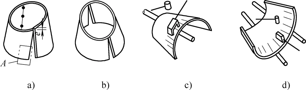
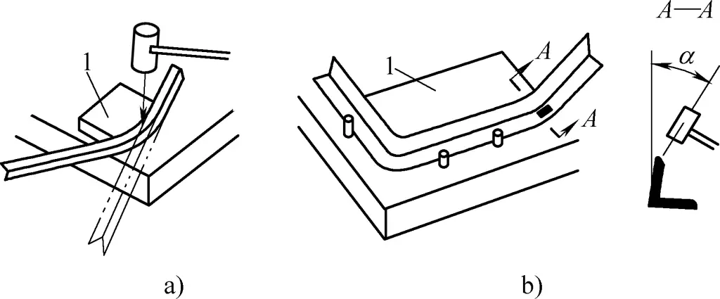
As shown in Figure 34, this is a manual bending method for angle steel. After heating the angle steel, it is clamped on mold 1 for inner bending, while the horizontal edge is hit with a sledgehammer to prevent it from lifting (see Figure 34a); for outer bending (see Figure 34b) the shaded area is heated to prevent the horizontal edge from collapsing, while the vertical face is struck with a sledgehammer (see cross-section A—A in Figure 34b) to prevent the angle from becoming smaller and the horizontal surface from lifting.
For profiles with a large cross-sectional area, even hot bending may not be sufficient for manual bending into shape, so mechanical bending must be used. The following are two examples of manual bending of profiles.
Flat steel is one of the common profiles, and due to its thickness, manual bending requires the use of molds for assistance. The designed mold for the flat steel ring is shown in Figure 35.
1—Mold Base Plate
2—Mold Plate
3—Handle
4—Bolt
5—Nut
6, 7—Rotating Pressing Bolt and Nut
8—Rolling Roller
9—Fixed Frame
10—Fixed Press Plate
11—Nut
12—Handle
13—Movable Pin
14—Flat Steel to be Bent
To ensure the shape of the flat steel ring meets design requirements, the mold base plate 1 and mold plate 2 are designed in a circular shape. The diameter of mold plate 2 should be increased by a certain shrinkage allowance based on the sectional shrinkage rate of the material (an increase of 0.1%–0.2% of the diameter) to account for cooling shrinkage. The edges and holes need to be machined to improve structural precision.
The thickness of mold plate 2 should be 2–1.5mm greater than the thickness of the flat steel being bent. This is to accommodate the heated flat steel. Additionally, the rolling roller 8 should also be machined to improve structural precision and the quality of the flat steel ring. It is designed in the shape of an I-beam with a larger top and smaller bottom, mainly to provide sufficient strength and ensure the flat steel ring fits the mold. The groove height should be 1–1.5mm greater than the combined height of plates 1 and 2.
The inner plane of the upper flange serves to prevent wrinkling, while both the upper and lower flanges provide guidance. The inner plane of the web plate serves to form the rolling shape.
The fixed press plate 10, nut 11, and handle 12 work together to press the flat steel tightly to prevent it from moving during bending.
To eliminate the straight sections and form a full circle in the flat steel ring, holes 1 and 2 are designed.
The steps and methods for manually bending a full circle flat steel ring are as follows:
1) Heat the flat steel material in a furnace to a yellow-orange color at a temperature of 900–1000℃, and let it sit for a short while.
2) Fix the fixed press plate 10 in hole 1 position, and align it with the rolling roller 8. Quickly insert and press the flat steel end tightly, then turn the handle 3 to start bending. When bending nears the fixed press plate 10, in order to match the two ends and eliminate the straight section, quickly move the fixed press plate 10 to hole 2, fix it, and continue bending until the ends overlap and cannot proceed further.
3) Remove the fixed press plate 10, take out the flat steel ring with the billet, and cut off the overlapping part to obtain a full circle flat steel ring.
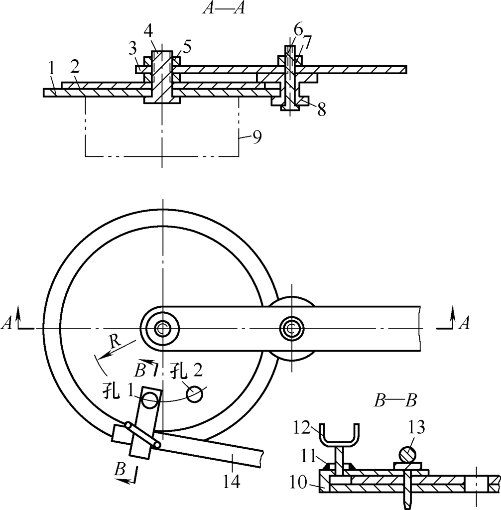
As shown in Figure 36, it is a concentric question mark-shaped ring. The ring is made of ϕ20mm diameter round steel. Due to the small production batch, it is generally bent manually using a mold.
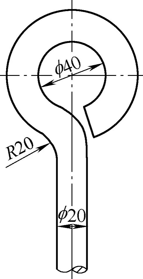
According to the dimensions given in Figure 36, to ensure that the diameter of the center hole is equal to 40mm, the forming cylindrical pin should be of fixed structure, the right cylindrical pin can be fixed or movable, and the left must be a movable cylindrical pin. The distance between the inner surfaces of each forming cylindrical pin should be 2-3mm larger than the diameter of the round steel (see Figure 37).
1, 2, 3, 4 — Bending Order
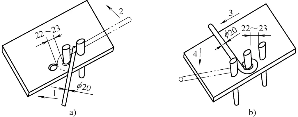
Figure 37a shows the situation of bending an eccentric ring. Insert the round steel between the central and right cylindrical pins, and bend from position 1 to position 2 following the arrow direction to form an eccentric ring.
Figure 37b shows the bending to form a concentric ring as required by the design. Bend back from position 2 to position 3 following the arrow direction, then insert the cylindrical pin into the left hole, and bend the round steel from position 3 to position 4 following the arrow direction to form the ring.
For cold or hot manual bending of flat steel, round steel, or small-diameter round tubes at any angle, use the mold shown in Figure 38.
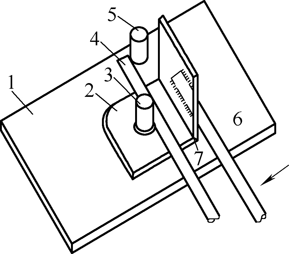
1—Platform
2—Rotating Angle Steel Mold
3—Cylindrical Pin
4—Workpiece
5—Fixed Cylindrical Pin
6—Handle
7—Contact Point
Weld the cylindrical pin 3 onto the platform 1, then fit the rotating angle steel mold 2, which has a handle 6 welded on with pre-drilled holes, onto the pin 3. The 5 is a fixed cylindrical pin.
Place the workpiece 4 between the cylindrical pin 3 and the fixed cylindrical pin 5, use force to turn the handle 6, the rotating angle steel mold 2 will move along the direction of the arrow. When the workpiece 4 touches the contact point 7, it will rotate together with the rotating angle steel mold 2. Continuous application of force can bend the workpiece to any angle.