Comprehensive Overview of Hose Couplings and Their Materials
In the intricate world of hose couplings, understanding the nuances between different types and materials can be the key to…

Sawing is the process of separating steel material through the cutting motion of saw teeth. Sawing can not only cut through metal but also make notches or seams on it. In riveting work, sawing is commonly used to cut profiles or small plates, and it is divided into manual sawing and mechanical sawing.
A hand saw consists of a saw bow and a saw blade. The saw bow is a tool used to hold and tighten the saw blade, available in fixed and adjustable types, as shown in Figure 3-8.
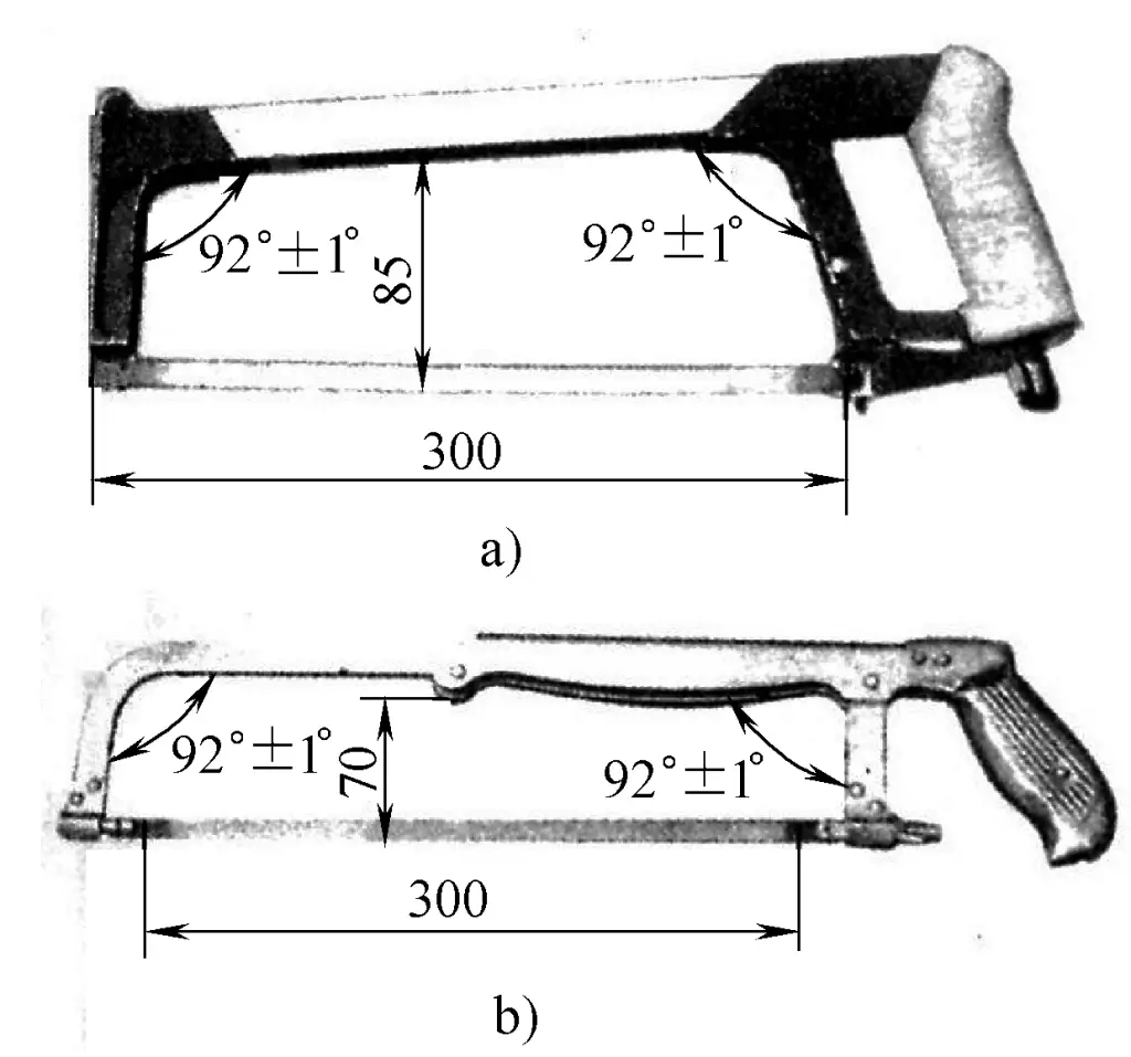
a) Fixed type
b) Adjustable type
The saw blade is made of carbon tool steel. Common saw blades are about 300mm long, 12mm wide, and 0.8mm thick. Saw blade specifications are divided into coarse, medium, and fine teeth based on the tooth pitch. The number of teeth per 25mm length of the saw blade is used to indicate this, with coarse-toothed saw blades having 14~18 teeth, medium-toothed saw blades having 24 teeth, and fine-toothed saw blades having 32 teeth.
Coarse-toothed saw blades are suitable for sawing soft metals such as copper and aluminum, as well as thick workpieces. Fine-toothed saws are suitable for sawing hard steel, sheet metal, and thin-walled tubes, etc. Medium-toothed saw blades are commonly used for machining ordinary steel, cast iron, and medium-thickness workpieces. Figure 3-9 shows the impact of tooth pitch coarseness on sawing. The arrangement of the saw teeth is often wavy, as shown in Figure 3-10, to reduce friction on both sides of the saw cut.
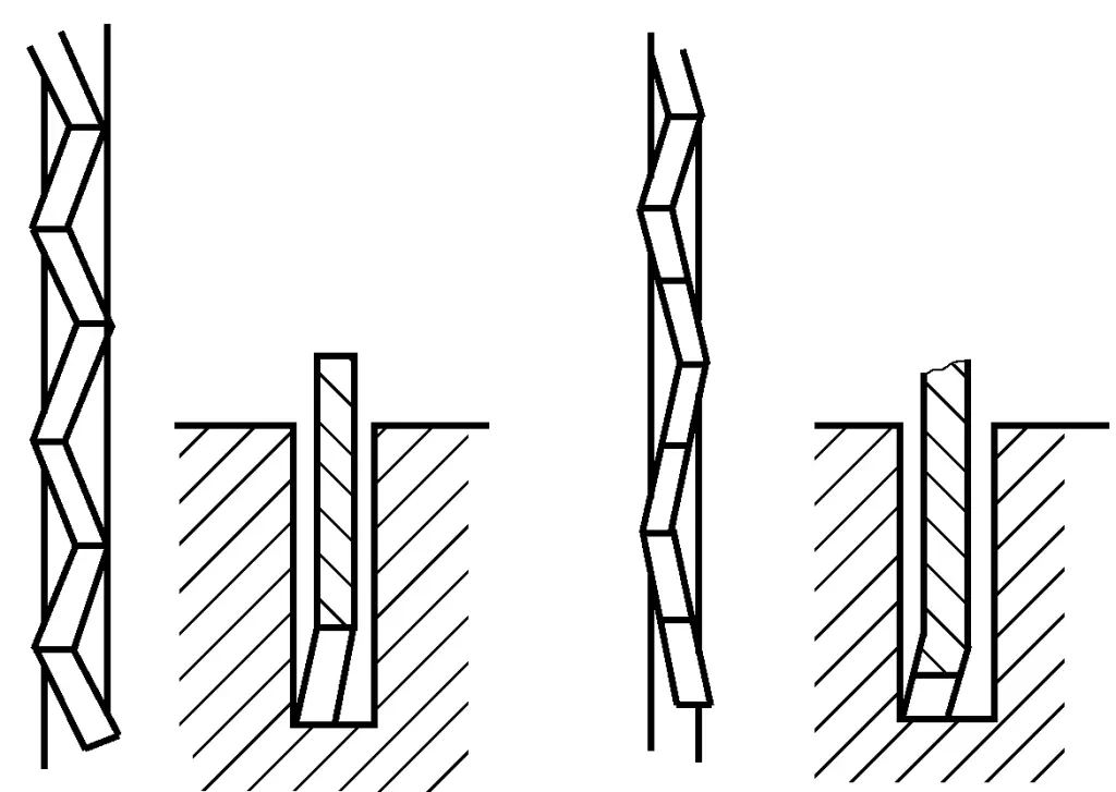
a) Cross-shaped
b) Wavy-shaped
Choose the appropriate saw blade based on the material and thickness of the workpiece, ensuring that the number of teeth sawing at the same time is more than two.
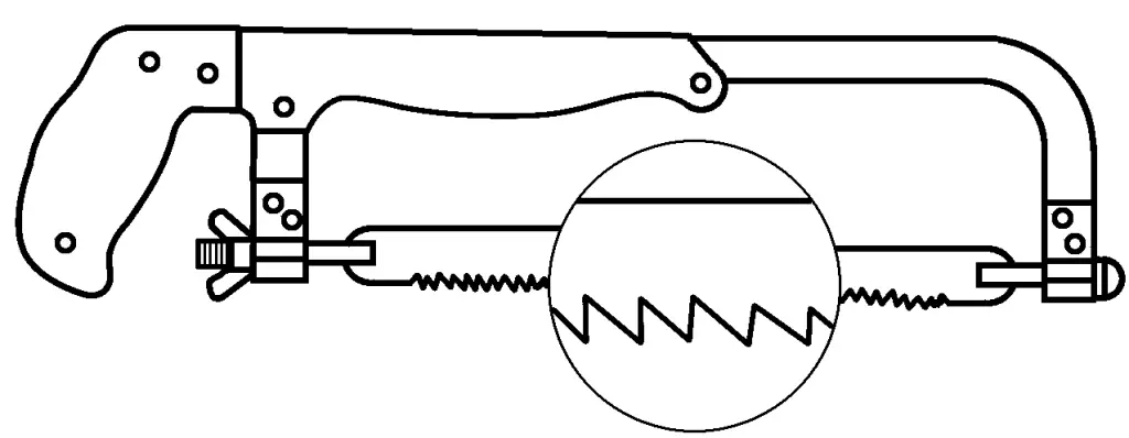
Install the saw blade on the saw bow with the teeth facing forward, as shown in Figure 3-11. The tension of the saw blade should be appropriate, otherwise it is easy to break the saw blade during sawing.
When clamping the workpiece, the saw cut should not be too far from the jaws to avoid vibration and breaking the saw blade during sawing.
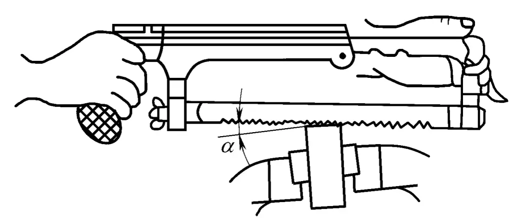
When starting to saw, the saw blade should be tilted at a certain angle, the tilt angle should be less than 15°, as shown in Figure 3-12, and the reciprocating stroke of the saw bow should be short, the pressure should be light, and the saw blade should be perpendicular to the work surface. After making the saw cut, gradually change the saw bow to a horizontal direction back and forth.
During sawing, the saw bow should reciprocate in a straight line without swinging; apply pressure when pushing forward, exert even force, and gently glide over the workpiece when returning. The sawing speed should not be too fast, usually 30~60 times per minute. Use the full length of the saw blade during sawing to avoid rapid dulling of the middle part of the blade. Use machine oil for lubrication when sawing steel materials. When nearly through sawing, the force should be light.
The sawing method should be determined according to the different shapes of materials, as shown in Figure 3-13 for the method of sawing pipes. When sawing pipes, the saw blade should change angles along the pipe wall. When sawing angle steel, saw the edges of the angle steel first.
Chiseling is a method of cutting metal by striking a chisel with a hand hammer. Chiseling work is mainly used in situations where mechanical processing is inconvenient. Chiseling also improves the accuracy of striking and lays a solid foundation for assembling and disassembling mechanical equipment.
Its work scope includes:
1) Removing flanges, burrs, etc., from the workpiece.
2) Cutting materials.
3) Chiseling grooves.
4) Sometimes also used for rough machining of smaller flat surfaces.
Common tools for chiseling consist of a hammer and a chisel.
The chisel consists of a head, cutting part, and chisel body. The head has a certain taper, with a slightly curved top, which facilitates stability through the centerline of the chisel. The chisel body is octagonal, mainly to prevent the chisel from rotating during chiseling.
It must meet two basic conditions. First: the material of its cutting part must be harder than the material of the workpiece. Second: its cutting part must be wedge-shaped, which is usually formed by forging carbon tool steel, followed by grinding and heat treatment.
There are many types of chisels, commonly used by cold workers are flat chisels and narrow chisels. As shown in Figure 3-14a, the cutting part of the flat chisel is flat, mainly used for chiseling planes and dividing thin plates, and sometimes also used to remove waste edges and burrs from workpieces. As shown in Figure 3-14b, narrow chisels are used for slotting, picking weld roots, etc.
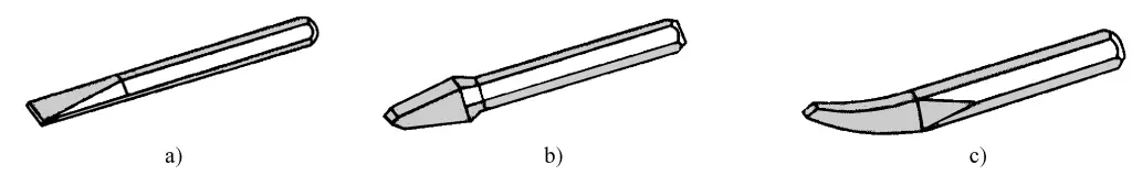
a) Flat chisel
b) Narrow chisel
c) Oil groove chisel
When the chisel becomes blunt, it needs to be sharpened. The method of sharpening the chisel’s wedge angle is shown in Figure 3-15. Hold the chisel with both hands and sharpen it on the edge of the rotating grinding wheel. During sharpening, the cutting edge must be higher than the center of the grinding wheel, move left and right across the full width of the wheel, and control the direction and position of the chisel to ensure the required wedge angle is ground.
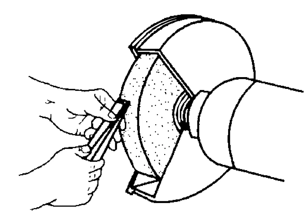
The pressure applied on the chisel during sharpening should not be too great, the movement should be smooth and even, and it should be frequently dipped in water for cooling to prevent annealing.
The hammer consists of a hammerhead, wooden handle, and wedge as shown in Figure 3-16, and its specifications are indicated by the weight of the hammerhead. The commonly used 1.5-pound hammer has a handle length of about 350mm, and the wooden handle is inserted into the hammer hole and wedged tight with a wedge to prevent the hammerhead from falling off.
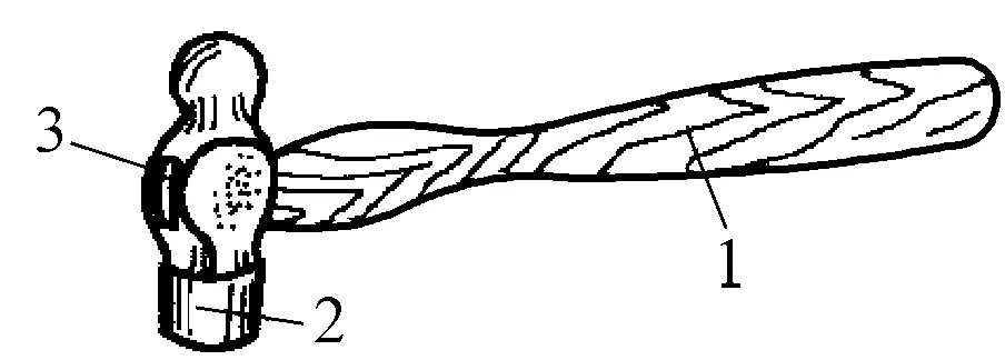
1 – Wooden handle
2 – Hammerhead
3 – Slanting wedge
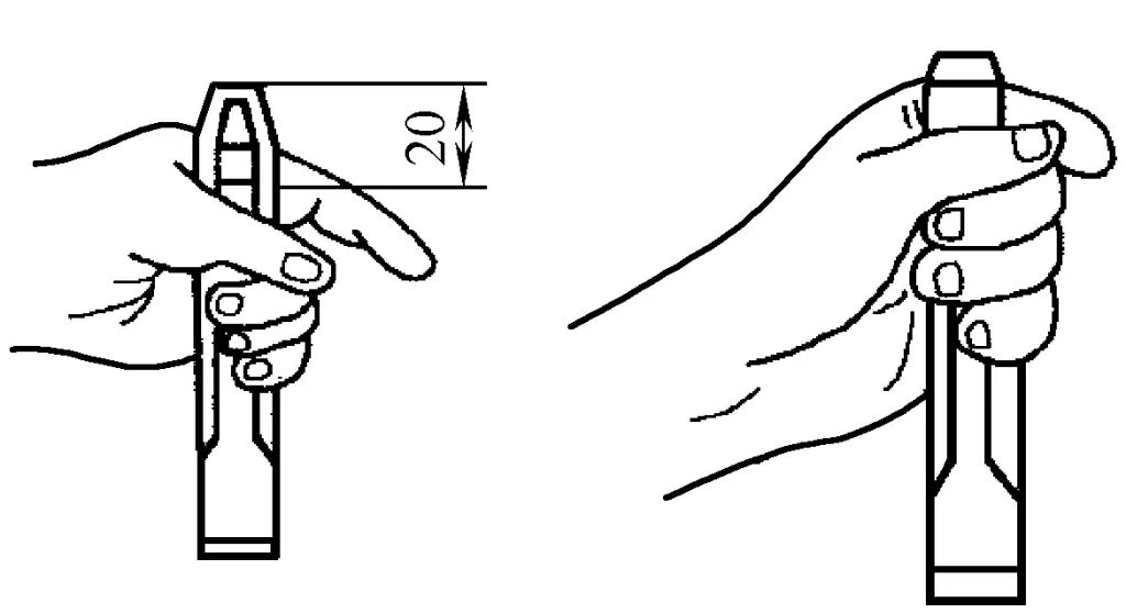
The chisel should be held with the middle finger, ring finger, and little finger of the left hand, with the thumb and index finger naturally touching. The tail end of the chisel should protrude 20mm from the hand, as shown in Figure 3-17. Do not grip the chisel too tightly to reduce the vibration of the chisel on the hand during chiseling.
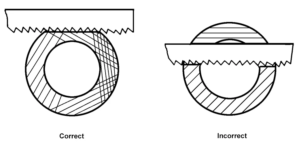
During chiseling, keep the forearm naturally flat to maintain the correct angle of the chisel. When the chisel is at the correct angle, the cutting back angle is about 5°~8°, as shown in Figure 3-18.
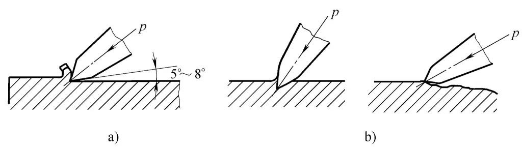
a) Correct
b) Incorrect
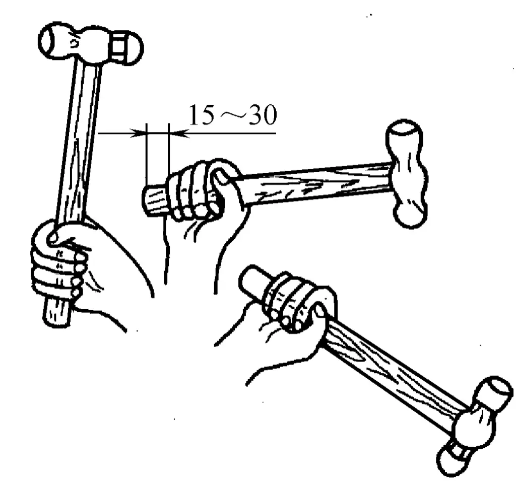
Hold the hammer with your right hand, using a full-finger grip. The thumb gently presses on the index finger, the base of the thumb aligns with the direction of the hammerhead, and the tail of the handle protrudes about 15~30mm, as shown in Figure 3-19.
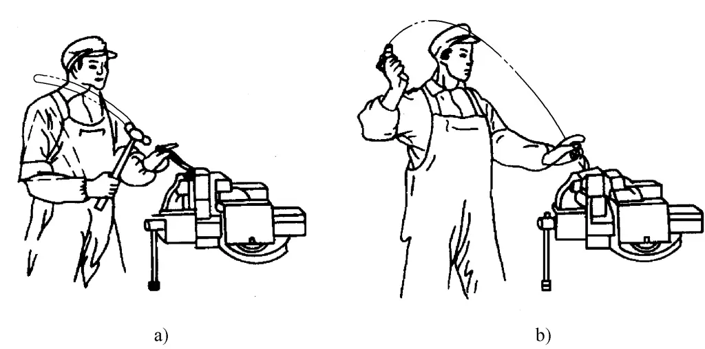
To fully exert greater hammering force, the operator must maintain the correct standing posture. As shown in Figure 3-20, the left foot steps half a step forward, both feet stand naturally, the body’s center of gravity is slightly towards the back foot, and the eyesight falls on the chiseling part of the workpiece.
There are three methods of swinging a hammer: wrist swing, elbow swing, and arm swing. The force of the hammer strike is smallest with the wrist swing, larger with the elbow swing, and largest with the arm swing. The elbow swing is the most widely used, and the elbow and arm swings are shown in Figure 3-21.
a) Elbow swing
b) Arm swing
The general hammering speed is 40-50 times per minute. The hammer should be accelerated when striking down, which can increase the force of the hammer strike.
As shown in Figure 3-22.
(2) Chiseling steps and methods
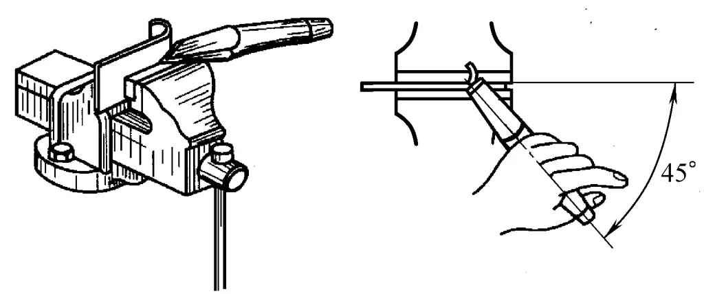
There are two methods of chiseling, one is to clamp the plate material in the bench vise for chiseling, as shown in Figure 3-23. When chiseling, the plate material is clamped along the line flush with the jaws of the vise, and the chisel is used along the jaws and diagonally against the plate material (at about a 45° angle) chiseling from right to left.
The hammering force during chiseling should be determined based on the thickness of the chiseled plate material, and should not be too great to avoid tearing the workpiece. During the chiseling process, it is important to maintain the tilt of the chisel to ensure the cutting back angle. If the cutting back angle is improper, it is easy to cause chiseling run-off or damage to the jaws of the vise.
Another method is to chisel the plate material on an iron anvil. For larger-sized plate materials or chiseling lines that have curves and cannot be chiseled on a bench vise, it is necessary to perform chiseling on an iron anvil, as shown in Figure 3-24.
At this time, the cutting edge of the chisel used for cutting should be ground into an appropriate arc shape to make the chisel marks from front to back connect smoothly; when chiseling straight segments, the width of the chisel cutting edge can be wider; when chiseling curved segments, the width of the blade should be determined based on its radius of curvature, so that the chisel marks can basically match the curve.
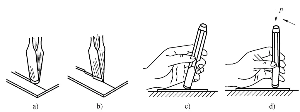
When chiseling, it should be done from front to back. Initially, the chisel should be placed diagonally like shearing, then gradually moved to vertical, as shown in Figure 3-25c and Figure 3-25d, chiseling in sequence. For this workpiece, straight parts are chiseled on a bench vise, and curved parts are chiseled on an iron anvil.
1) When chiseling sheet metal on a bench vise, the chisel line should be flush with the jaws, and the sheet metal should be firmly clamped.
2) When chiseling on a bench vise, the back part of the chiseling should be flush with the plane of the jaws, and the edge of the blade should be slightly tilted upwards to prevent damaging the surface of the jaws.
3) When chiseling on an iron anvil, the chisel blade must first align with the chisel line and be angled accordingly. It is necessary to prevent the subsequent chisel from misaligning with the previous one, causing the chiseled edge to be wavy. Also, do not chisel onto the anvil itself. If no iron pad is used, chisel out all the marks on the sheet metal without cutting through, then break the sheet metal.
4) If the wooden handle of the hammer is found to be loose or damaged, it should be immediately secured or replaced. The handle should not have oil on it to prevent it from slipping during use.
5) If there are obvious burrs on the head of the chisel, they should be ground off in time.
Notching is a manual shearing method used in cold work, characterized by its independence from the work position and the shape of the parts.
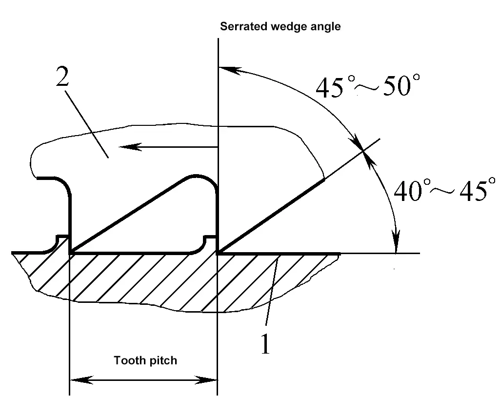
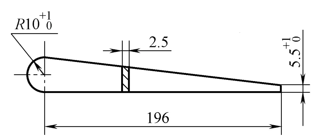
The main notching tools are the upper and lower notchers. During notching, the upper notcher is used in conjunction with the lower notcher. The upper notcher is generally forged and made from carbon tool steel, as shown in Figure 3-26. The lower notcher can be made from waste blade pieces or processed from steel rails, as shown in Figure 3-27.
Although notching is a labor-intensive and inefficient manual operation, it is still commonly used in production due to its simple tools, flexible use, and ability to notch curves.
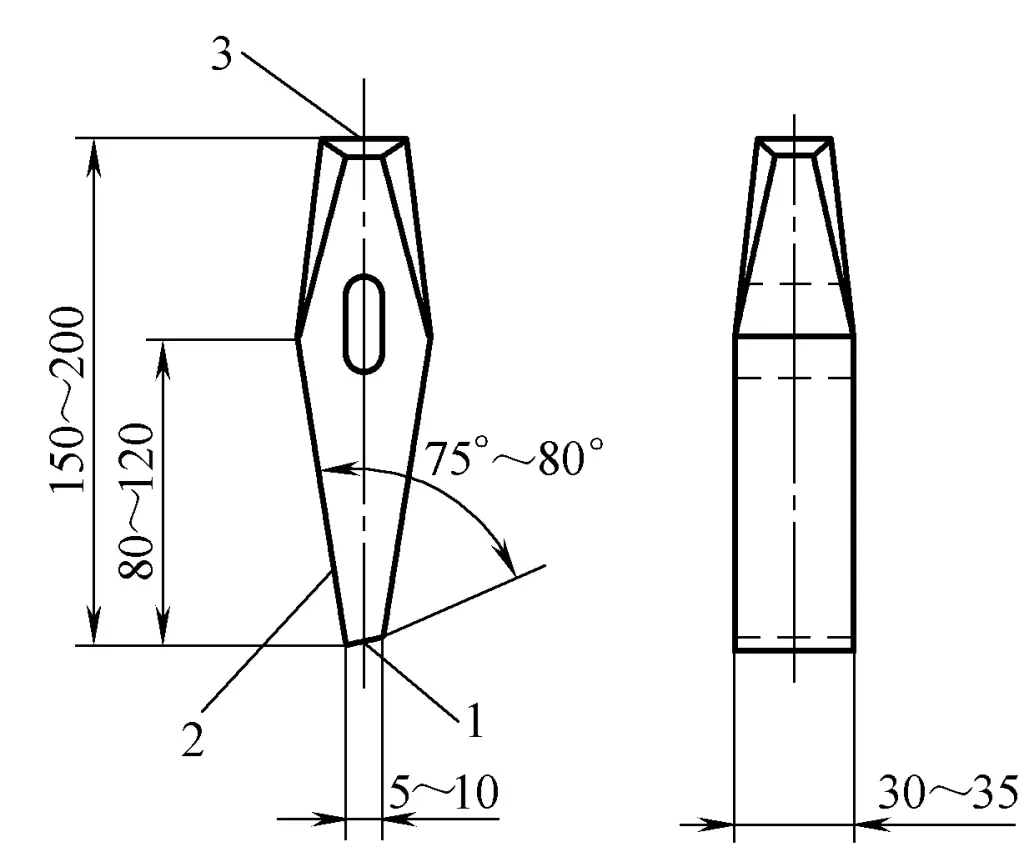
1-Front
2-Back
3-Top
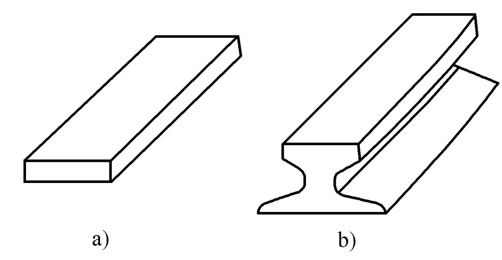
a) Waste scissors blade
b) Rail
Before using the notcher, it should be sharpened according to the standard geometric shapes and sizes shown in Figure 3-26. During use, if the blade of the notcher becomes blunt, damaged, or the top develops a burr, it must be ground on a grinding wheel to meet the usage requirements. The steps and methods for sharpening the upper notcher are as follows:
1) Grinding the back of the chisel. When grinding, hold the chisel with both hands and grind on the front of the grinding wheel as shown in Figure 3-28a. To make the back of the chisel flat, move it steadily up and down, left and right against the grinding wheel surface during grinding.
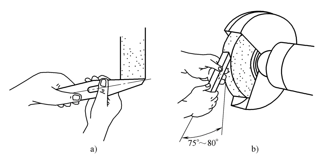
a) Grinding the back
b) Grinding the front
2) Grinding the front of the chisel. After the back has been ground, grind the front correctly to ensure the accurate wedge angle of the chisel. During grinding, hold the chisel with both hands in front of the grinding wheel, setting the angle between the back of the chisel and the tangent at the grinding point of the wheel to about 75°~80°, as shown in Figure 3-29b.
Also, make sure to move the chisel steadily up and down, left and right, and do not apply too much pressure on the grinding wheel. To avoid overheating the cutting edge of the chisel during grinding, frequently immerse the chisel in water to cool it.
3) Grinding the overall shape of the chisel. The overall shape of the forged upper chisel may not be very regular, and it should be ground to the standard shape.
4) Grinding quality inspection.
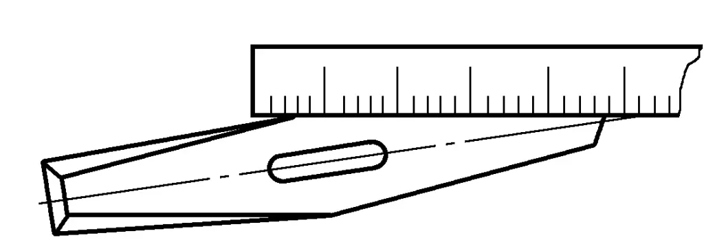
① When checking the straightness of the back of the chisel, place a steel ruler vertically on the back of the chisel as shown in Figure 3-29, raise it to eye level, and observe against a bright background to see if the steel ruler fits tightly against the back of the chisel, thus judging the flatness of the back of the chisel.
Visually inspect the blade edge and front to see if they are straight, and check for any rough grinding marks and annealing phenomena.
Use a template to check the wedge angle of the chisel, as shown in Figure 3-30.
1) Preparation for quenching
① Prepare coke ovens, coke, etc.
② Prepare a water tank and fill it with cooling water.
③ Prepare tools such as fire tongs.
2) Quenching operation
The quenching process of the chisel is divided into two stages: quenching and tempering. During quenching, place the chisel vertically in the coke oven, with its cutting edge buried in the coke. When the cutting edge of the chisel is heated to 770~800°C (cherry red) for 20~30mm, use fire tongs to remove the chisel from the oven and quickly place it vertically into the water to a depth of 5~8mm, and slowly move along the surface of the water to accelerate cooling, increase quenching hardness, and ensure there is no clear boundary between the hardened and unhardened parts to prevent breakage.
When the part of the chisel that emerges from the water just turns black, remove it from the water and utilize the residual heat at the top for tempering (equivalent to low-temperature tempering). At this time, pay attention to observing the color of the chisel blade. Generally, the color of the chisel blade is white when it just comes out of the water, and as the temperature of the blade edge gradually rises, the color changes from white to yellow, then from yellow to blue.
When the blade part turns yellow, immerse the entire chisel in water to cool, this tempering temperature is called “yellow heat”; when the chisel blade turns blue, immerse it entirely in water, this tempering temperature is called “blue heat”. Practice has proven that when the chisel used in cold work adopts a tempering temperature between “yellow heat” and “blue heat”, the hardness and toughness of the chisel meet the requirements.
3) Hardness check
Use a moderately worn flat file with medium teeth, apply slight pressure and push forward along the front of the chisel, if there is some resistance and metal filings are filed off, then the hardness is insufficient; if it feels very smooth, the sound is crisp, and no metal filings are filed off, then the hardness is appropriate.
Hold the top of the chisel and chop down on the edge of a scrap steel plate with the chisel blade edge, if the edge is undamaged, it indicates that the chisel’s hardness and toughness are suitable, if there are chips or cracks, it is too hard; if the blade edge is dented and deformed, it indicates insufficient hardness.
Before using the grinding wheel, first check whether there are any cracks in the grinding wheel disc, and whether the gap between the bracket and the grinding wheel (about 3mm) is appropriate. If the gap is not appropriate, adjust it to avoid accidents during the grinding process due to the workpiece getting caught.
After the grinding wheel starts, wait for it to operate normally before using it. During grinding, the operator should stand on the side of the grinding wheel machine, not directly in front of it.
When sharpening the blade, wear protective goggles.
Chisel quenching should use clean water, generally around 15°C.
For more complex stamping parts, arranging the process steps reasonably has a great impact on improving the quality of stamping. Generally, the sequence of stamping is from outside to inside, from straight to arc, and from short to long.
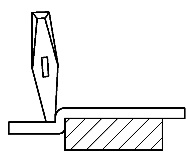
If the size of the stamping parts is large or it is not conducive to support after rotation, to maintain the stability of the workpiece, a support plate can be placed next to the lower die, but it is necessary to ensure that the plate fits flush with the upper surface of the lower die.
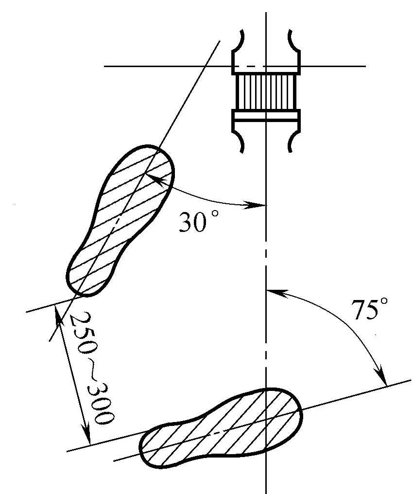
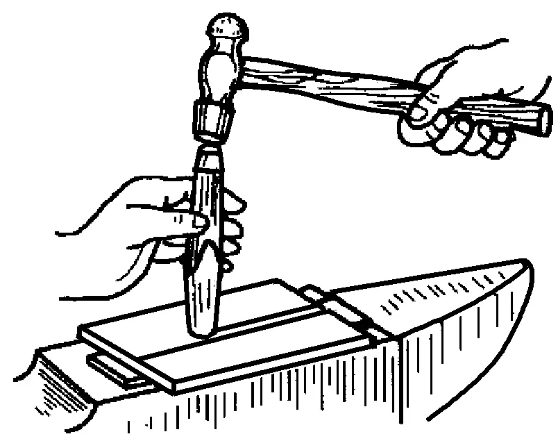
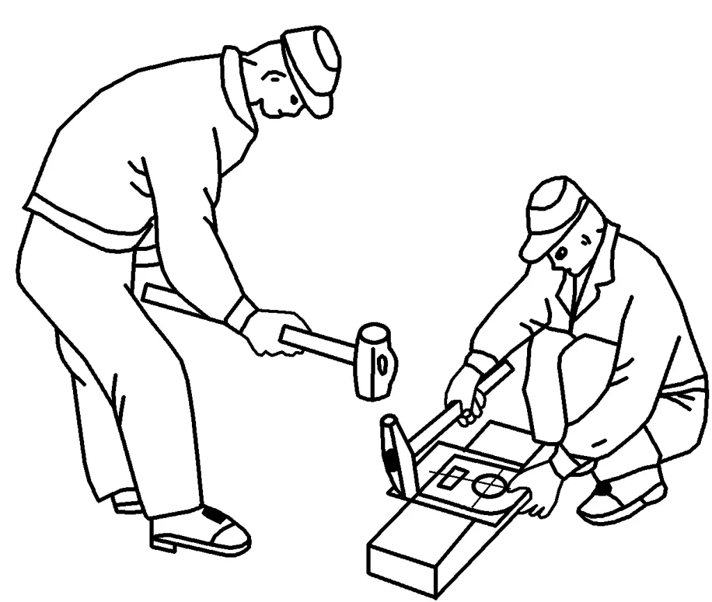
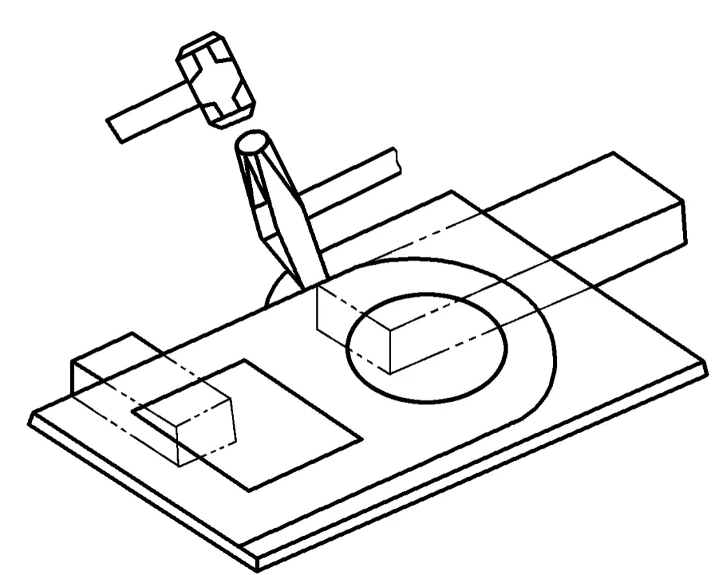
The stamping operation is mainly completed by the cooperation of the holder and the hammer operator. Their positions and postures are shown in Figure 3-31. The holder naturally squats down, supports the plate material flat on the lower die with the left hand, holds the upper die with the right hand, and pays attention to aligning the die edge with the stamping line; the hammer operator stands on one side of the lower die edge, and it is advisable for the two to form a 90° angle.
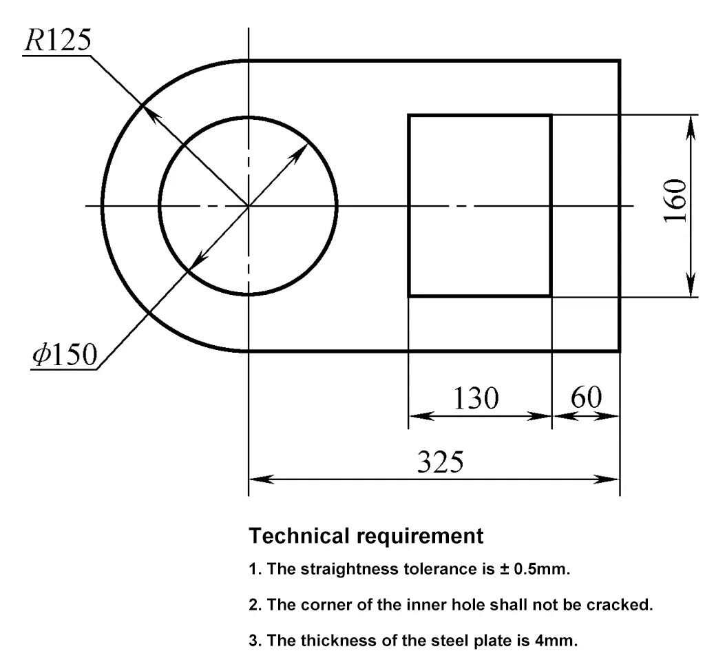
1) After preparing the marked sheet metal, draw the pattern on the sheet metal at a 1:1 scale (or according to the template).
To facilitate accurate alignment when starting the cut, first determine the starting point of the cut, then draw the starting line to the edge of the sheet metal to align with the lower cutter edge, as shown in Figure 3-33.
2) Determine the cutting sequence.
Analyze the cutting workpiece diagram, the cutting sequence is arranged as shown in Figure 3-34.
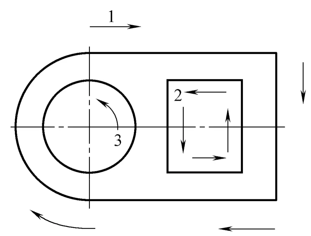
3) Cutting of straight segments.
The cutting sequence is arranged as shown in Figure 3-34.
① Start cutting.
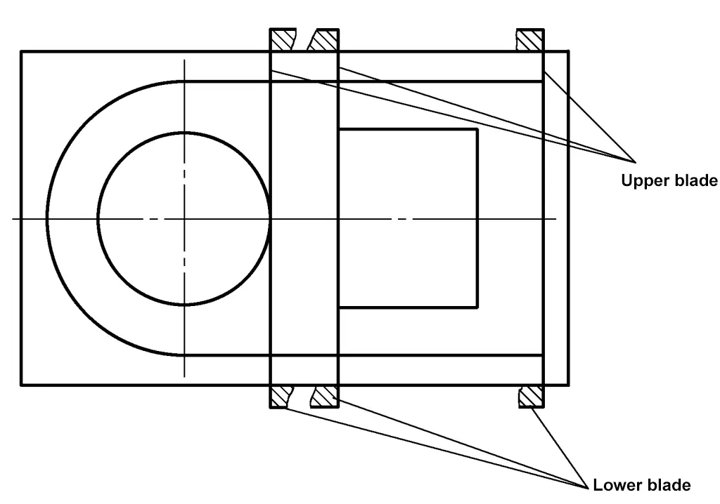
Place the plate flat on the lower die, with the excess material extending beyond the cutting edge to facilitate alignment by passing a line, making the cutting line coincide with the lower cutting edge. Align the upper die blade with the cutting line on the plate, protruding 1/3 of the blade width, and close to the lower cutting edge. At the same time, keep the front of the upper die vertical to the steel plate being cut, and the blade edge at an angle of 10°~15° to the steel plate, as shown in Figure 3-35.
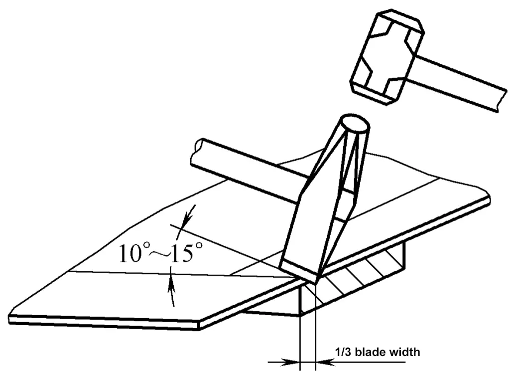
When starting the cut, use a lighter hammer strike to allow for corrections and to prevent damage to the tool from the blades of the upper and lower dies colliding after the steel plate is cut through. Start the cut to open the gap, and after confirming the accuracy of the opening line, use the side of the lower part of the upper die resting on the side of the lower die as a reference for alignment, and begin cutting in straight segments.
② Cutting. During the cutting process, the cutting line of the steel plate should always align with the blade of the lower die, maintain the proper angle of the upper die, and keep the upper and lower die blades tight. Otherwise, not only will the plate not be cut through, but it will also cause bending and deformation, as shown in Figure 3-36. During cutting, to improve quality, constantly correct any deviation in cutting and change the hammering force. This requires the operator to pay close attention and coordinate closely, and the hammerer must follow the commands of the person controlling the die.
4) Cutting the curved parts.
① Start cutting.
When cutting to the curved part of the workpiece, first cut off the excess material of the already pierced straight part so that it does not hinder alignment during the curved cutting. To reduce deformation of the plate during cutting, place the circular part of the workpiece on the lower die; continuously rotate the workpiece, always using the end of the lower die for cutting, as shown in Figure 3-37.
2) Cutting.
When cutting curves on sheet material, since both the upper and lower cutting edges are straight, each cut can only produce a straight line. Therefore, the essence of cutting curves is to cut straight line segments along the tangent positions of the curve, forming an external polygon around the curve. The shorter the cut line segments, the closer it is to the curve. This requires: each cutting amount should be as small as possible and the sheet material should be rotated frequently. The hammering should be brief and the force appropriate.
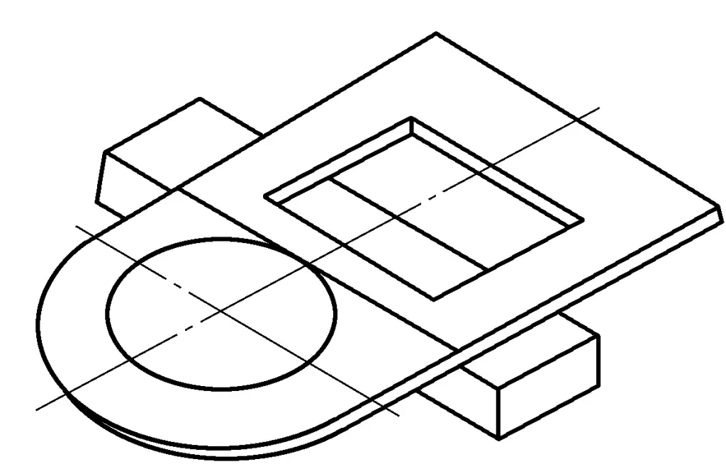
5) Cutting of internal square holes.
To make the opening of the internal square hole cutting accurate, you can align as shown in Figure 3-38. When starting the cut, the sharp angle of the upper cutting edge touches the sheet material, and gently hammer the opening. At this time, the workpiece at the starting cut is not yet cut through. After cutting a length of 2-3 times the width of the blade, place the upper cutting edge flat at the starting cut to clear the root and cut through, as shown in Figure 3-39. The cutting method after opening is the same as the aforementioned straight line cutting.
a) Align the marking
b) Align the ruler over the line
6) Cutting of internal circular holes.
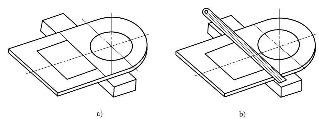
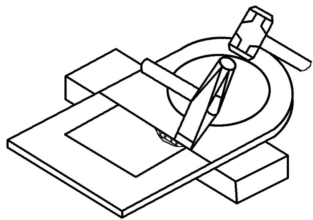
The cutting of internal circular holes should first select a good starting point. For ease of starting, the starting point should generally be chosen at a position that is easy to clamp the sheet material, and a tangent of the inner circle is drawn through the starting point to align the starting point with the lower cutting edge, as shown in Figure 3-40. The cutting method of internal circular holes is the same as the aforementioned curve cutting method.
7) Quality inspection of punched parts.
① Check whether the dimensions of the punched parts meet the requirements of the drawings.
② Check whether the edges of the punched parts are neat and free from significant burrs, burrs, and tearing.
③ Check whether the straightness of the straight sections and the roundness of the curved sections of the punched parts meet the requirements.
1) The punch blade should be sharpened in time if it becomes blunt or rolls at the top.
2) During the punching process, ensure that the sheet material is placed steadily and aligned accurately.
3) The punch operator and the person assisting with the steel plate should wear gloves to prevent cuts from steel burrs.
4) The punched workpieces should be neatly arranged, and scrap should be cleaned up in time to ensure civilized production.
The grinding wheel machine can be used to grind various tools, such as chisels, drill bits, scrapers, etc. It consists of a grinding wheel, motor, grinding wheel base, bracket, and protective cover.
The texture of the grinding wheel is brittle, and it rotates at high speed during operation. Improper force during use can cause the grinding wheel to shatter and cause personal accidents. Therefore, when installing the grinding wheel, it must be balanced so that there is no vibration when the wheel rotates, and strict adherence to safety operating procedures is required:
1) A newly installed grinding wheel must be test-run for 30~40mm, then check whether the grinding wheel and bearings rotate smoothly, and whether there are vibrations or other adverse phenomena.
2) Regularly check the grinding wheel for cracks and whether the threads at both ends are locked.
3) The grinding wheel machine must be equipped with a protective cover, and it is not allowed to be removed arbitrarily.
4) The distance between the grinding wheel and the shelf should not be too large, generally the gap should be less than 3mm, to prevent the grinding piece from being drawn into the gap and crushing the grinding wheel during blade grinding.
5) After the grinding wheel starts, wait until the speed stabilizes before grinding. The operator should stand on the side, not on the plane of rotation of the grinding wheel, to avoid injury in case the grinding wheel shatters.
6) Do not use the sides of the grinding wheel to grind workpieces, and it is forbidden for two people to use one grinding wheel for grinding at the same time.
7) Do not grind heavy and large workpieces on the grinding wheel machine, and do not use excessive force to press the grinding wheel for grinding.
8) Do not touch the grinding wheel with fingers to prevent grinding off fingers or causing injury.
9) It is best not to exceed ten minutes of continuous operation time for the grinding wheel machine to avoid overloading and burning out the motor.
10) The grinding wheel machine should not grind wood, stone, bricks, tiles, and other materials.
11) The grinding wheel machine must not be equipped with a reverse switch, and the rotation direction must not face the main passage.
12) The work support must be installed firmly, and the surface of the support must be flat.
13) Grinding wheels that are not round, have cracks, or have less than 25mm remaining should not be used.
14) The power cord of the portable electric grinding wheel must not have any insulation damage or leakage. Insulating gloves should be worn during use, start the machine first, then contact the workpiece.
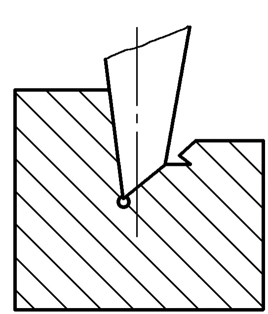
The angle between the two sides of the chisel cutting edge is called the wedge angle B. The smaller the wedge angle, the sharper the chisel edge, but the weaker the strength; the larger the wedge angle, the better the strength, but the greater the chiseling resistance.
Therefore, the selection of the chisel’s wedge angle should be minimized while ensuring strength. Generally, when chiseling high carbon steel and cast iron, the wedge angle is set to 60°~70°; when chiseling medium carbon steel and other medium hardness materials, the wedge angle is set to 50°~60°; when chiseling soft materials like copper and aluminum, the wedge angle is set to 30°~50°, as shown in figure 3-41.
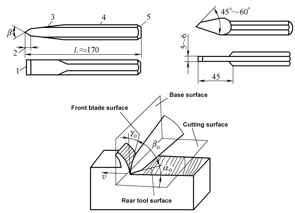
1-All Cutting Edges
2-Cutting Part
3-Bevel
4-Handle
5-Head