I. Overview
1. Principle of High-Pressure Water Cutting
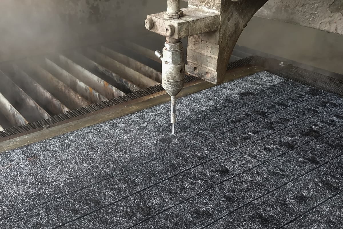
The principle of high-pressure water cutting is to pressurize water to an ultra-high pressure of 100~400MPa, and then jet it onto the workpiece to be cut through a throttle orifice (Φ0.15 ~ Φ0.4mm) at 2~3 times the speed of sound, converting the water’s potential energy into kinetic energy of the water jet, with a flow speed of up to 900m/s or more. By utilizing the impact of the high-speed, high-energy dense water jet, like a sharp blade, it performs the cutting.
The range of materials that can be cut with high-pressure water cutting technology is very broad, capable of cutting many materials that conventional cutting methods cannot or are difficult to cut, such as various metals and their alloys (stainless steel, titanium, aluminum, copper, etc.), ceramic materials, glass, stone, wood, softwood, plastics, rubber, multi-layer composite materials, honeycomb materials, and concrete, etc.
2. Classification of High-Pressure Water Cutting
(1) Pure water type.
Mainly used for cutting non-metallic materials, with simple equipment and low cost, but also lower cutting capability.
(2) High-pressure abrasive type.
Abrasive particles are added to the water jet, and after mixing, form an abrasive water jet. The water jet serves as a carrier to accelerate the abrasive particles. Due to the large mass and high hardness of the abrasive, the kinetic energy of the abrasive water jet is greatly increased, making it the main method for cutting metals.
High-pressure water and abrasives are delivered to the cutting gun through pipes, mixed in the mixing chamber of the cutting gun, and then sprayed out from the nozzle, with water pressure usually between 100~400MPa.
(3) Low-pressure abrasive type.
The water and abrasive are pre-mixed in a pressurized storage tank, then the mixed abrasive slurry is sent to the cutting gun’s nozzle for spraying, with relatively low water pressure, usually between 20~100MPa.
3. Characteristics of high-pressure water cutting
(1) The temperature rise in the cutting area is very small, the temperature in the cut is below 100°C, there is no thermal deformation or heat-affected zone on the workpiece, thus the material and properties of the material being cut are not changed.
(2) High quality of the cut, with no burrs, slag hanging, the cutting surface is vertical, flat, and has a high degree of smoothness.
(3) The width of the cut is relatively small. During pure water cutting, the diameter of the water jet is between 0.1~0.5mm; the nozzle aperture for abrasive type is about 1.2~2.5mm.
(4) Cutting can start or stop at any point on the workpiece.
(5) Does not produce gases or dust harmful to human health.
(6) Can be used in places where open flames are strictly prohibited.
The main problem is the noise is too loud, reaching 98~106dB, with the peak noise frequency at 2~3kHz, which is quite harsh, therefore operators should wear earplugs.
II. Composition of the High-Pressure Water Jet Cutter
A high-pressure water jet cutter generally consists of a high-pressure water generator, cutting gun and nozzle, drive device, water treatment device, and a water collection tank, as shown in Figure 1.
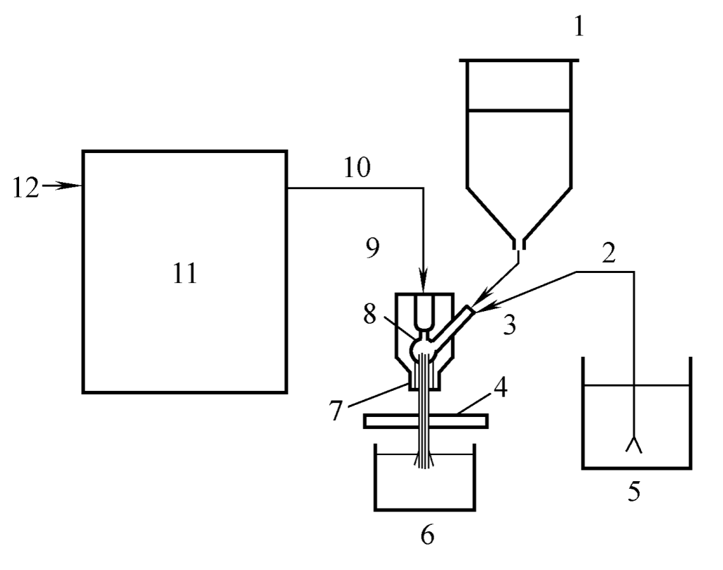
1 – Abrasive Hopper
2 – Abrasive or Slurry
3 – Abrasive Inlet
4 – Workpiece
5 – Abrasive Slurry Supply Tank
6 – Water Collection Tank
7 – Abrasive Nozzle
8 – Water Nozzle
9 – Cutting Gun
10 – High Pressure Water
11 – Ultra High Pressure Pump
12 – Water Inlet
1. High Pressure Water Generating Device
Generally, a booster is used to increase the high pressure water supplied by the pump from 20~32MPa to ultra high pressure of 100~400MPa.
2. Cutting Gun and Nozzle
The structural schematic diagram of the cutting gun and nozzle components is shown in Figure 2. Pure water type nozzles are mostly made of diamond or sapphire, with a simple structure, and the nozzle hole is straight cylindrical, with a diameter of 0.1~0.5mm.
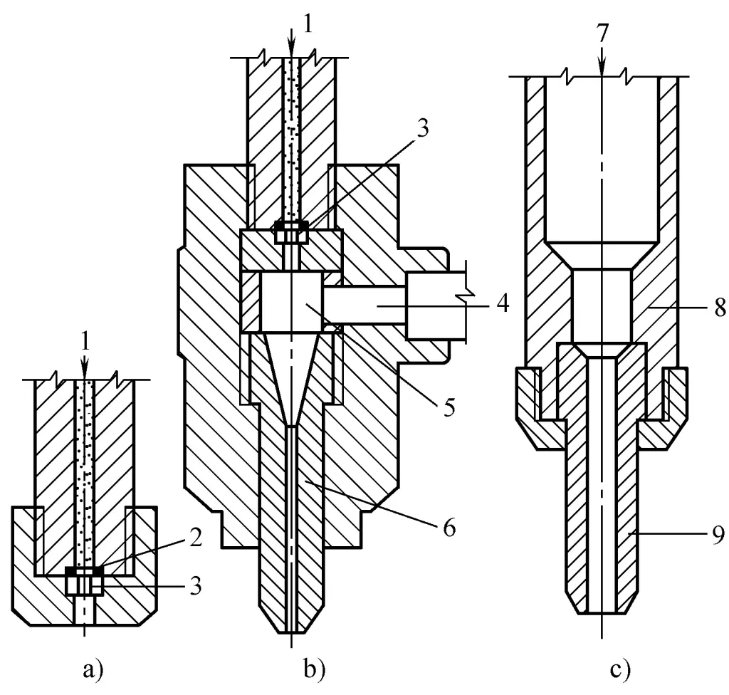
a) Pure water type
b) High pressure with abrasive type
c) Low pressure with abrasive type
1-High pressure water
2-Sealing gasket
3-Water nozzle
4-Abrasive
5-Mixing chamber
6-Abrasive nozzle
7-High pressure water mixed with abrasive
8 All cutting gun body
9 Nozzle
The structure of the abrasive type (high pressure) is relatively complex, where the material and aperture of the water nozzle are the same as those of the pure water type, while the abrasive nozzle is commonly made of hard alloys such as tungsten carbide. The nozzle channel consists of two sections, the upper part is a cone with a slowly changing taper, and the lower part is a very long straight cylinder, with an aperture of 1~2mm. The nozzle used in the form of low-pressure pre-mixed abrasive (see figure 2c) is also made of tungsten carbide, but the conical part is shorter.
3. Drive device
It usually adopts a worktable moving along the X-axis and a cutting gun moving along the Y-axis. The maximum driving speed is about 50m/min. The positioning accuracy can reach ±0.1mm, and the repeatability accuracy is ±0.03mm. During the cutting process, to maintain a relatively stable distance between the nozzle and the workpiece, a capacitive height auto-adjustment device is generally equipped when cutting metal.
4. Water treatment device
Includes filtration and chemical treatment. After filtering out suspended particles in the water larger than 0.45μm, ion exchange or reverse osmosis is used for chemical treatment to remove other undesirable compounds in the water.
5. Water collection tank
Used to recover the ejected water and abrasives. Since the ejected water jet and abrasives still have residual kinetic energy and noise, metal balls are generally placed in the water collection tank to buffer.
6. Hardness of several abrasives
(see table1)
Table 1 Hardness of Various Abrasives
| Abrasive | Hardness Value (Mohs Hardness/Vickers) |
| Quartz Sand (SiO2 ) | 7/1000 |
| Olivine (Mg2SiO4 , Fe2SiO4 ) | 6.5/800 |
| Nickel Slag (Fe2O3 , SiO2 etc.) | 7/1000 |
| Copper Slag (Fe2O3 , SiO2 etc.) | 7~7.5/1000~1200 |
| Aludur Sand (Fe2O3 , SiO2 , Al2O3 ) | 7~7.5/1000~1200 |
| Zirconium Silicate (ZrSiO4 ) | 7.5/1200 |
| Corundum (Al2O3 ) | 9/2100 |
III. Process Parameters of High-Pressure Water Cutting
Table 2 Process Parameters for Abrasive High-Pressure Water Cutting of Metal Materials
| Material | Material Thickness/mm | Water Pressure/MPa | Nozzle Diameter/mm | Cutting Speed/mm·min-1 |
| C-Mn Steel | 12 | 75 | 3 | 50 |
| 25 | 75 | 25 | ||
| 30 | 75 | 20 | ||
| 50 | 69 | 15 | ||
| Stainless Steel | 3 | 75 | 3 | 200 |
| 8 | 70 | 60 | ||
| 10 | 69 | 35 | ||
| 50 | 70 | 15 | ||
| 25 | 245 | 0.33/1.2 | 30 | |
| 50 | 10 | |||
| 50 | 196 | 0.4/1.5 | 15 | |
| 13 | 309 | 0.25/0.76 | 150 | |
| 25 | 70 | |||
| Aluminum | 3 | 90 | 3 | 500 |
| 3 | 69 | 350 | ||
| 85 | 196 | 0.4/1.3 | 20 | |
| 3 | 206 | 0.3/1.2 | 750 | |
| 80 | 0.46/1.6 | 20 | ||
| 150 | 0.46/1.6 | 10 | ||
| 1.6 | 309 | 0.25/0.76 | 1270 | |
| 12 | 500 | |||
| 100 | 500 | |||
| Aluminum Alloy | 6 | 69 | 3 | 250 |
| 10 | 69 | 125 | ||
| 12 | 74 | 130 | ||
| 25 | 90 | 70 | ||
| Steel + Tungsten Chromium Cobalt Alloy (2mm) | 17 | 69 | 3 | 50 |
| Steel + Tungsten Chromium Cobalt Alloy (6mm) | 31 | 69 | 3 | 60 |
| Steel + Tungsten Chromium Cobalt Alloy (8mm) | 18 | 69 | 3 | 15 |
| Low Carbon Steel | 3 | 75 | 3 | 210 |
| 10 | 69 | 32 | ||
| Iron | 25 | 245 | 0.46/1.6 | 20 |
| 50 | 10 | |||
| 12 | 309 | 0.25/0.76 | 100 | |
| 50 | 70 | |||
| 175 | 10 | |||
| Mn30%-Al18% Steel | 10 | 75 | 3 | 40 |
| Copper | 3 | 75 | 3 | 150 |
| Titanium | 12 | 69 | 3 | 36 |
| 25 | 25 | |||
| 4 | 206 | 0.33/1.2 | 600 | |
| 10 | 0.46/1.6 | 140 | ||
| 25 | 0.46/1.6 | 40 | ||
| Ductile Cast Iron | 15 | 309 | 0.25/0.76 | 150 |
| Inconel Alloy | 2 | 245 | 0.46/1.6 | 900 |
| 15 | 80 |
Note: The value of the nozzle aperture is the diameter of the pure water type nozzle / the diameter of the abrasive type nozzle.

