Hydraulic Cylinders: Working Principles & Types
What powers the heavy machinery used in construction and manufacturing? Hydraulic cylinders play a pivotal role, transforming hydraulic energy into…
Hydraulic and pneumatic symbols form the foundation of understanding fluid power systems. These symbols represent components such as pumps, valves, and actuators, and their connections and functions within a system. By decoding these symbols, engineers can design, analyze, and troubleshoot hydraulic and pneumatic circuits with precision. This article breaks down the key symbols, providing clarity on their meanings and uses. Through this guide, you will gain the ability to read and interpret fluid power diagrams, enhancing your technical skills in system design and maintenance.
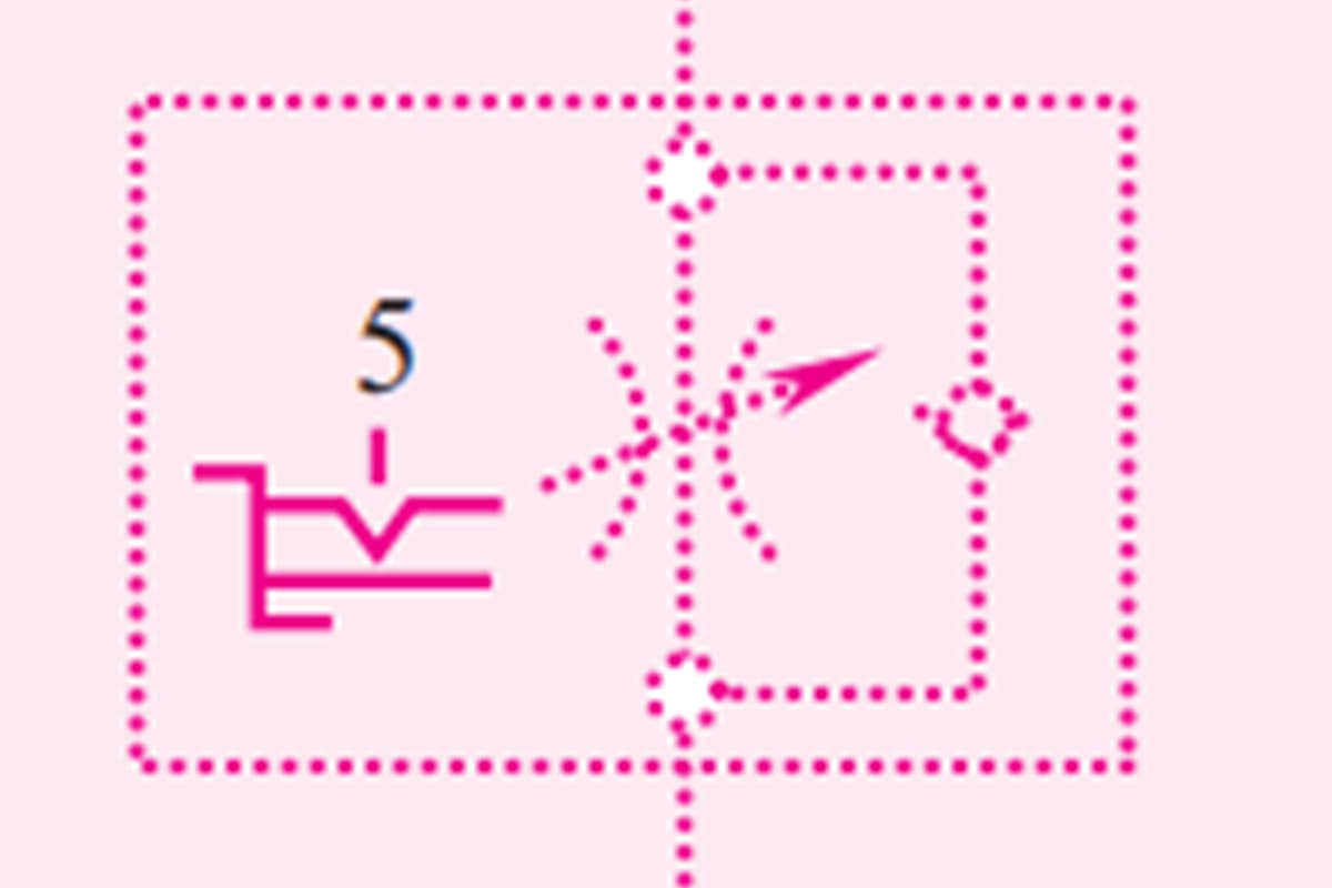
Table 1 Basic Symbols, Pipelines, and Connections (GB/T 786.1—2009)
| Name | Symbol |
| Oil Supply and Return Lines |  |
| Control Lines, Drain Lines, Flushing Lines, and Vent Lines |  |
| Combination Component Outline | |
| Connection of Two Fluid Lines | 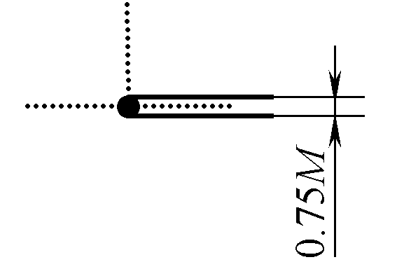 |
| Connecting Line | 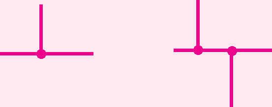 |
| Crossing Line | |
| Hose Assembly |  |
| Interface |  |
| Control Line or Drain Line Interface |  |
| Closed Line or Interface |  |
| Rotary Joint |  |
| Three-Way Plug Valve |  |
| Three-Way Rotary Joint |  |
| Quick-Disconnect Coupling without Check Valve, Disconnected State | |
| Quick-Disconnect Coupling with Check Valve, Disconnected State | |
| Quick-Disconnect Coupling with Two Check Valves, Disconnected State |
Table 2 Control Structures and Control Methods
| Name | Symbol |
| Control Mechanism with Separate Handle and Positioning Pin |  |
| Push Rod with Adjustable Stroke Limiter |  |
| Push or Pull Control Mechanism with Positioning Device |  |
| Manual Locking Control Mechanism |  |
| Control Mechanism with 5 Locking Positions | 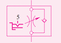 |
| Roller Lever for Single Stroke Direction Operation | 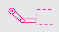 |
| Control Mechanism with Stepper Motor |  |
| Single-acting solenoid, action towards the valve core | 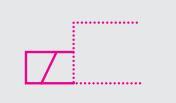 |
| Single-acting solenoid, action away from the valve core |  |
| Double-acting electrical control mechanism, action towards or away from the valve core | 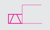 |
| Electrically operated pneumatic pilot control mechanism |  |
| Electrically operated hydraulic pilot control mechanism with external oil supply | 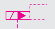 |
| Mechanical feedback | 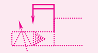 |
| Pneumatic reset, pressure supplied from the valve inlet | 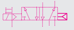 |
| Pneumatic reset, external pressure source | 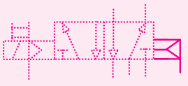 |
| Double-acting electrical control mechanism, action towards or away from the valve core, continuous control |  |
Table 3 Pumps, Motors, and Cylinders
| Name | Symbol |
| Variable pump | 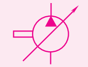 |
| Bidirectional flow, variable pump with external leakage oil path and unidirectional rotation | 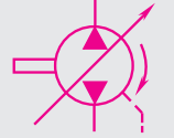 |
| Fixed displacement pump or motor with unidirectional rotation | 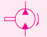 |
| Joystick control, pump with restricted disc angle | 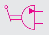 |
| Swing actuator or rotary drive with restricted swing angle, bidirectional flow | 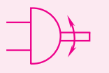 |
| Single-acting single-rod cylinder, return stroke by spring force | 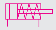 |
| Double-acting single-rod cylinder |  |
| Single-acting cylinder, plunger cylinder | 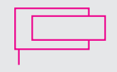 |
| Double-acting band-type rodless cylinder, with end cushioning on both ends of the piston | 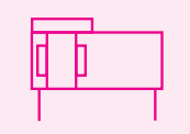 |
| Double-acting double-rod cylinder, different piston rod diameters, cushioning on both sides, adjustable on the right side | 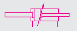 |
| Single-acting clamp with permanent magnet piston |  |
| Motor | 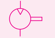 |
| Air compressor | 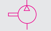 |
| Vacuum pump | 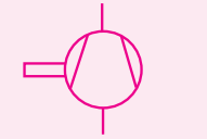 |
| Bidirectional swing motor with fixed flow rate and direction change | 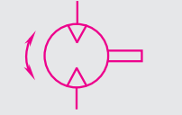 |
| Single-acting semi-rotary cylinder or swing motor | 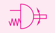 |
| Single-acting telescopic cylinder | 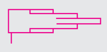 |
| Double-acting telescopic cylinder |  |
| Double-acting cylinder with end-of-stroke positioning | 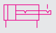 |
| Electro-hydraulic servo-controlled variable hydraulic pump | 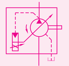 |
| Variable pump with constant power control | 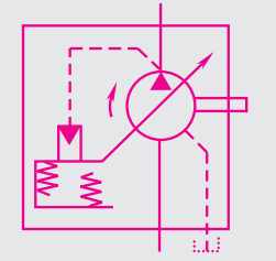 |
| Continuous booster, converts gas pressure p 1 to liquid pressure p 2 | 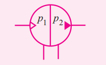 |
Table 4 Control elements
| Name | Symbol |
| Two-way two-position directional control valve, two-way two-position, push control mechanism, spring return, normally closed | 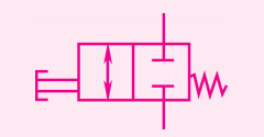 |
| Two-way two-position directional control valve, two-way two-position, solenoid operated, spring return, normally open | 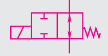 |
| Two-way four-position directional control valve, solenoid operated, spring return | 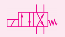 |
| Two-way three-position directional control valve, solenoid operated, spring return, normally closed | 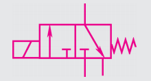 |
| Relief valve, direct-acting, opening pressure adjusted by spring | 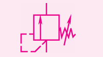 |
| Sequence valve, manually adjustable setpoint | 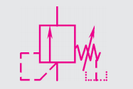 |
| Sequence valve with bypass valve | 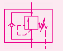 |
| Two-way pressure reducing valve, pilot-operated, external drain type | 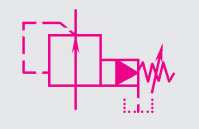 |
| Three-way pressure reducing valve (hydraulic) | 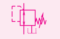 |
| Adjustable flow control valve |  |
| Adjustable flow control valve, unidirectional free flow | 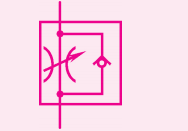 |
| Flow divider, splits input flow into two output streams | 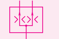 |
| Check valve, allows free flow in one direction only |  |
| Double check valve, pilot-operated | 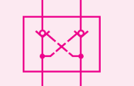 |
| Shuttle valve (“OR” logic), automatically connects the higher pressure inlet to the outlet | 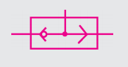 |
| Proportional relief valve, direct-acting, controls hydraulic solenoid directional seat valve by adjusting spring length via solenoid | 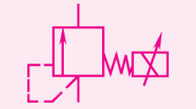 |
| Proportional flow control valve, direct-acting | 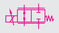 |
| Proportional directional control valve, direct control | 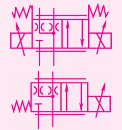 |
| Pressure and directional control cartridge valve insert, valve seat structure area 1:1 | 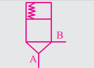 |
| Pressure and directional control cartridge valve insert, normally open, valve seat structure, area 1:1 | 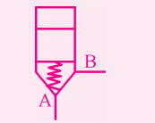 |
| Proportional relief valve, pilot control, with solenoid position feedback | 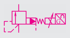 |
| Externally controlled sequence valve | 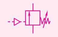 |
| Internally reversible pressure regulating valve | 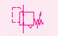 |
| Pressure reducing valve, remote pilot, adjustable, forward flow only | 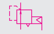 |
| Quick exhaust valve | 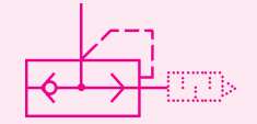 |
| Double pressure valve (“AND” logic), and only when both inlets have pressure will a weaker signal be output from the outlet | 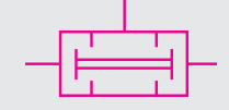 |
Table 5 Auxiliary components
| Name | Symbol |
| Filter | 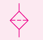 |
| Tank breather filter | 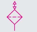 |
| Filter with auxiliary magnetic core | 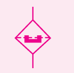 |
| Filter with optical blockage indicator | 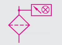 |
| Cooler without coolant flow indicator | 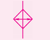 |
| Liquid-cooled cooler | 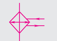 |
| Heater | 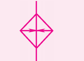 |
| Temperature regulator | 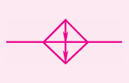 |
| Tachometer |  |
| Air source treatment device, including manual drain filter, manually adjustable overflow pressure reducing valve, pressure gauge, and oil mist separator. (The above is a detailed schematic, the below is a simplified diagram) | 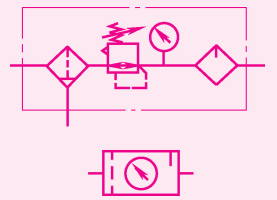 |
| Oil mist separator | 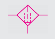 |
| Air dryer | 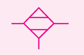 |
| Oil mist lubricator | 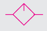 |
| Single-acting pressure medium converter, converts gas pressure to equivalent liquid pressure, and vice versa | 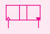 |
| Diaphragm type gas accumulator | 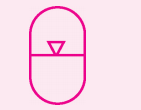 |
| Piston type gas accumulator | 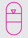 |
| Gas cylinder |  |
| Pressure gauge |  |
| Differential pressure gauge |  |
| Thermometer |  |
| Liquid level indicator | 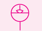 |
| Flow indicator |  |
| Flow meter | 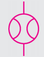 |
| Lubrication point |  |
| Vacuum separator | 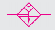 |
| Manual drainage fluid separator | 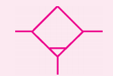 |
| Vacuum generator | 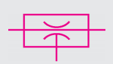 |
| Air tank |  |