I. Overview
1. Process Introduction and Drive Mode
The press brake is a processing machinery that bends metal sheets into shape in a cold state. It uses the simplest universal molds to bend the sheet metal at various angles in a straight line, as shown in Figure 1. The operation is simple, with good versatility, low mold cost, easy replacement, and the machine itself has only one basic motion – an up and down reciprocating straight line motion.
Different geometric shapes of sheet metal parts can be made on the press brake, and the finished products are lighter than rolled profiles, with a beautiful appearance. Components welded from bending parts, such as various types of chassis, cabinets, panels, brackets, etc., are 30% to 50% lighter in weight than similar cast steel parts and are simpler to manufacture. Therefore, the press brake is increasingly widely used in various industrial sectors, especially in electronics and telecommunications, instrumentation, household appliances, computers, automotive industry, aerospace industry, and locomotive vehicles, etc.
In recent years, the development of press brakes has been very rapid, with a variety of structural forms, continuously new functions, and the precision and degree of automation have been increasing, forming an important and rapidly developing category of machine tools, with strong demand in both domestic and international markets, and fierce competition.
Initially, press brakes were mechanically driven, but since the 1980s, they have been replaced by hydraulic drive methods. Currently, the vast majority (about 95%) of press brakes use hydraulic drive, with only a small number of small-scale mechanical press brakes still being produced.
However, in recent years, there has been the emergence of the latest mechanical drive directly driven by servo motors, which has the advantages of low energy consumption, noise, pollution, and cost, and is under development.
2. Two Main Bending Methods
(1) Air Bending
As shown in Figure 2, the shape of the die remains unchanged, the sheet metal is placed on the surface of the die, and the press brake’s ram drives the punch down, bending the sheet metal inside the die to a certain angle.
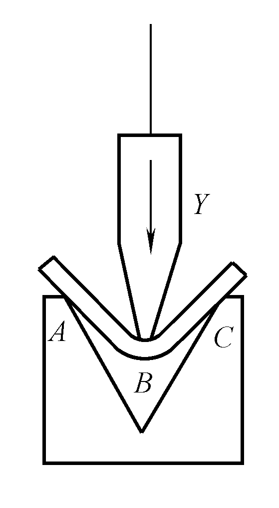
The angle of sheet metal bending depends on the depth of the punch entering the die, thus a pair of molds can be used to bend the workpiece into different angles. Its advantages are the simpler structure of the machine tool, smaller bending force, but the disadvantages are that the uneven thickness of the sheet metal affects the bending angle, there is a larger springback, and sheet metals with poor ductility are prone to cracks on the outer side of the bending area.
(2) Three-point bending
The characteristic of bending method shown in Figure 3 is that the depth H of the die’s base plate can be precisely adjusted and fixed, which is equivalent to adjusting the depth of the punch entering the die, but the adjustment is easier and more precise. During bending, the three points of contact b, a, c between the sheet metal and the mold are all on the same side surface of the sheet metal, therefore the thickness deviation of the sheet metal basically has no effect on the bending angle.
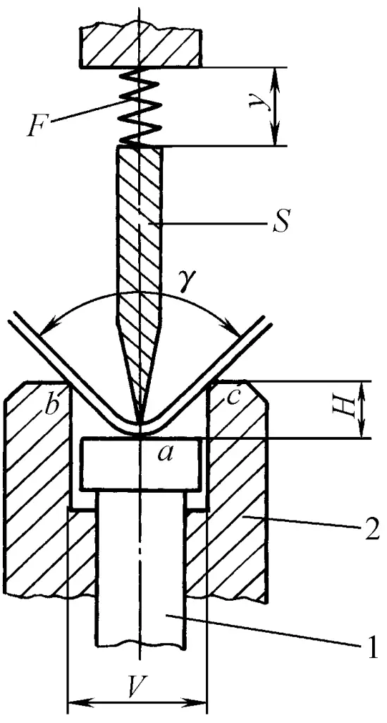
1—Base plate
2—Die
Moreover, both the top of the punch and the base plate of the die touch the sheet metal, changing the stress state of the bending area of the sheet metal. The outer side of the neutral layer changes from tensile stress during air bending to compressive stress, which is not prone to cracks, and the amount of springback is greatly reduced, achieving a bending precision of ±10’ . However, its punch hydraulic cushion and die depth adjustment mechanism are quite complex.
3. Brief introduction of the main body structure
The main body structure of the hydraulic press brake is divided into upper transmission and lower transmission types. The upper transmission main body structure is shown in Figure 4. The whole frame is welded from thick steel plates, mainly consisting of left and right vertical plates, which have sufficient strength and rigidity. Two hydraulic working cylinders 2 and 4 are installed on the left and right sides, respectively, to drive the ram 5 and the punch fixed on it to move up and down, while the die is fixed on the workbench 6.
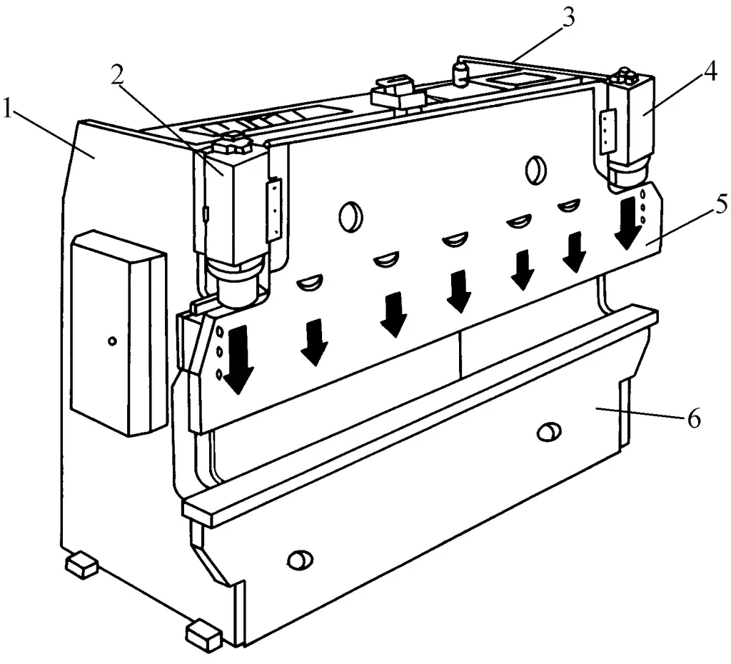
1—Left vertical plate
2—Left hydraulic cylinder
3—Right vertical plate
4—Right hydraulic cylinder
5—Ram
6—Workbench
A back gauge system is installed on the rear side of the frame to achieve precise positioning of the plate bending. During the bending process, the adjustment of the back gauge is the most frequent, and its positioning accuracy directly affects the dimensional accuracy of the workpiece bending edge.
The back gauge system generally adopts precise mechanical transmission, for example, in the PBB series CNC press brakes produced by Yawei, the back gauge system uses a digital AC servo motor drive, large lead precision ball screw transmission, and linear guide rail guidance.
The down-acting hydraulic press brake arranges the working cylinder in the middle of the lower beam, and the ram moves upwards during operation. Since the return is by gravity fall, the working cylinder can use a single-acting plunger cylinder, which is simple in structure. However, the main disadvantage is that the operator needs to continuously support the plate material during the ram’s ascent, making it inconvenient to operate.
It is generally considered suitable for thin plate bending on press brakes with small tonnage, short workpiece length, and short stroke. Japan’s Amada Company has been committed to the development and research of down-acting hydraulic press brakes, and has launched the Fine&Bender series.
4. Estimation of Bending Force
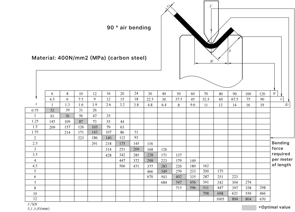
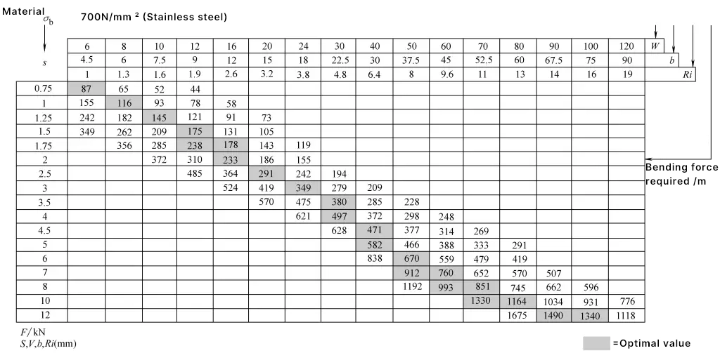
The bending force of a press brake is related to the thickness S of the plate being bent, the length of the bend, the mechanical properties of the plate material σb , the bending radius Ri, and the die opening width W. For air bending, the plate is generally considered as a simply supported beam, with the distance between supports being the die opening width V, and the load applied at the midpoint, to estimate the bending force based on air bending.
It can generally be found in Table 1. The P value found in the table is the bending force required per meter length of the plate material (kN), so it still needs to be multiplied by the actual length of the plate material being bent (m), with the corresponding σ b being 400MPa and 700MPa.
Table 1 Comparison Table of Plate Bending Forces (Air Bending) (Trumpf)
Related reading: Press Brake Tonnage Calculator
II. Synchronization System and Ram Positioning
In hydraulic press brakes, due to the large size in the width direction, it is generally driven by two hydraulic cylinders on the left and right to move the ram downwards. The synchronization system is used to ensure that the pistons of the two hydraulic cylinders can move synchronously with precision, thus ensuring that during bending, the lower surface of the ram and the punch is parallel to the worktable and the upper surface of the die.
Therefore, the synchronization system is a key device in hydraulic press brakes to ensure bending accuracy. The stop position control of the ram’s working stroke directly affects the depth of the punch entering the die, and thus, in the air bending mode, it is an important factor affecting the bending angle and bending quality.
Several different synchronization systems and ram positioning control methods are described as follows:
1. Torsion bar synchronization system
The working principle of the torsion shaft synchronization system is shown in Figure 5. Its main part is a thicker rigid torsion shaft 2, which is fixed at both ends on the inside of the left and right frames 1, and is connected on both sides through two small rams 3 and ram 4.
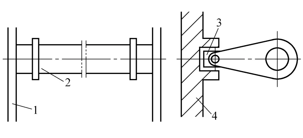
1—Frame
2—Rigid torsion shaft
3—Small ram
4—Working ram
When the ram is subjected to an offset load or the movements on both sides are not synchronized, the huge torsional stiffness of the torsion shaft balances it. This system structure is simple, with certain synchronization accuracy and offset load resistance capabilities, so it is still widely used in medium and small-sized press brakes. However, for press brakes with a very large nominal force, if a torsion shaft type is still used, the diameter of the torsion shaft must be very thick, which will greatly increase the weight of the machine, hence it is not suitable.
2. Electro-hydraulic servo synchronization system
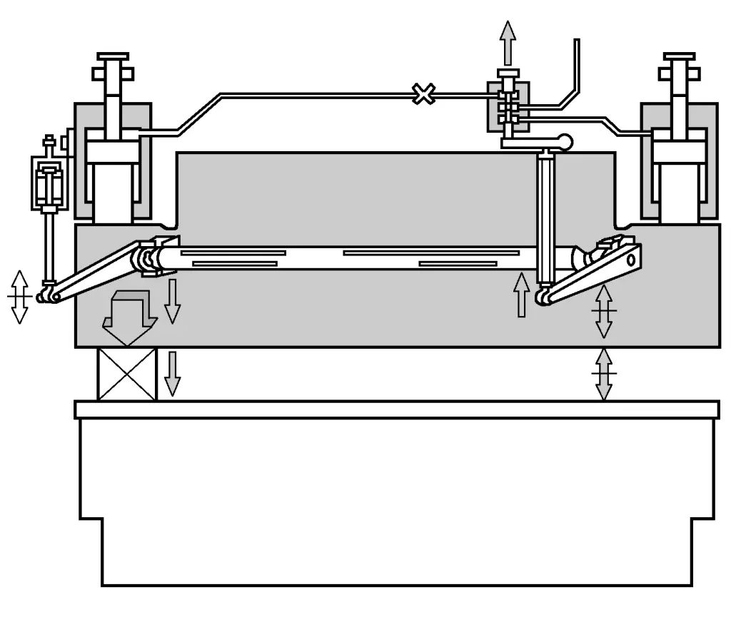
The working principle of the electro-hydraulic servo slide valve synchronization system is shown in Figure 6. The deviation caused by the tilt of the ram position is used as the input through the mechanical feedback system, which then controls the position of the servo slide valve, making the pressure and flow entering the hydraulic cylinders on both sides different, thereby correcting the deviation of the ram position. Its synchronization accuracy and offset load resistance are both higher than those of the mechanical type. The working principle of the electro-hydraulic servo rotary valve synchronization system is similar to that of the electro-hydraulic servo slide valve type.
3. Electro-hydraulic servo synchronization system and positioning control
This is currently the most widely used and highest precision synchronization system. It adopts a full closed-loop electro-hydraulic servo control technology. The ram position signal is fed back to the CNC system by grating scales on both sides, which then controls the opening size of the synchronization valve, adjusting the amount of oil entering the hydraulic cylinder, thereby controlling the synchronous operation of the ram.
Tianshui Forging Machine Tool Factory uses the electro-hydraulic servo proportional synchronization system and positioning control on its WE67Y series CNC press brake, as shown in Figure 7. The system consists of an electro-hydraulic proportional valve with pressure compensation and electrical feedback, grating scales, proportional amplifiers, and synchronous position control templates.
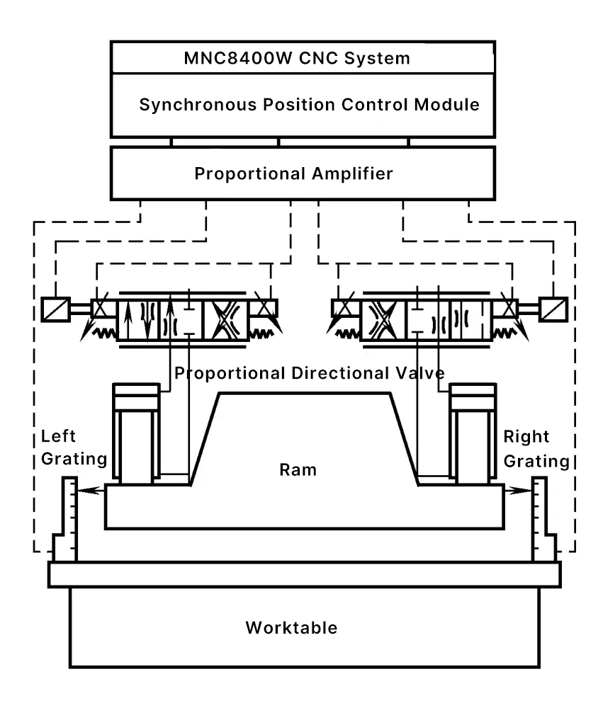
During the ram movement, the synchronous position control template detects the displacement of both ends of the ram through the linear grating scale, thereby calculating the synchronization error value of the ram, and according to the position value of the lower stop point sent by the host computer, performs digital synchronous adjustment and positioning control.
The working principle diagram of the synchronous position control template and proportional amplifier is shown in Figure 8.
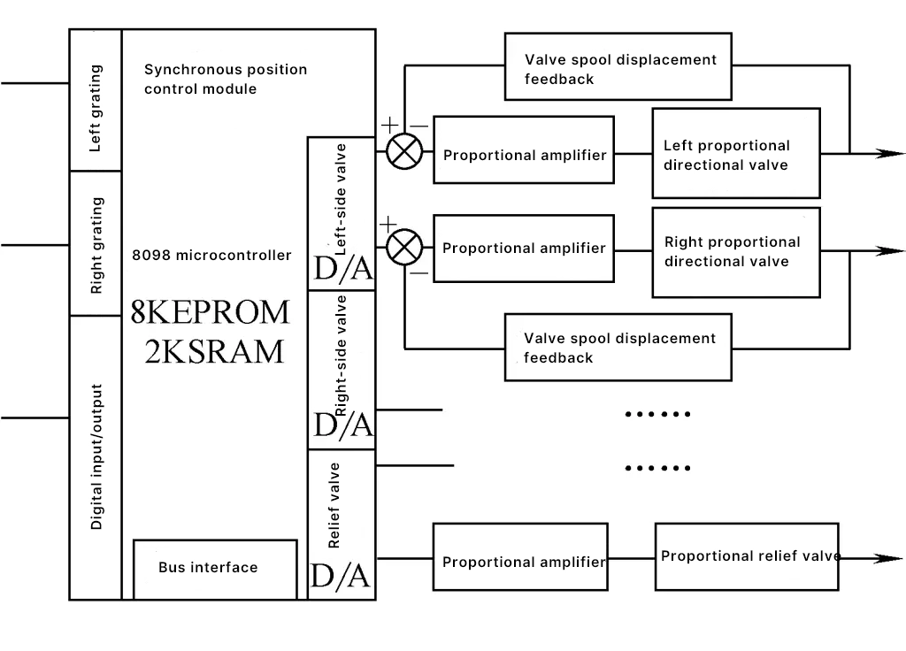
The design of the control template adopts PC assembly and STD bus forms, communicates with the host computer (MNC8400W), receives the host computer’s parameter data and control commands related to controlling the ram; realizes the displacement counting of the linear grating scales at both ends of the ram; receives the operator’s switch control signal for the ram; performs digital adjustment calculation, sends the proportional valve’s analog control voltage signal to the proportional amplifier, completing the synchronous adjustment, position control, and control of the action sequence and pressure of the press brake.
The proportional amplifier receives the analog voltage signal from the synchronous position control template, and detects the position signal of the proportional valve spool, completing the closed-loop control of the proportional valve spool through the proportional electromagnet.
Using a pressure compensator stacked under the proportional valve can make the system pressure change with the load, reducing energy loss and increasing system safety.
By using an electro-feedback proportional directional valve, the position of the valve core can be converted into a voltage signal through the feedback circuit and fed into the proportional amplifier, making the position control of the valve core a closed-loop state, thereby ensuring precise bending position. Compared with proportional directional valves without electrical feedback, electro-feedback proportional directional valves have simple control, stability, and high precision.
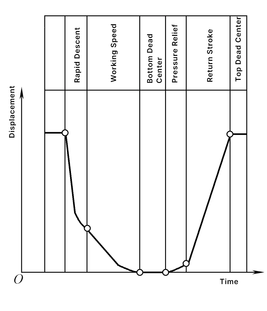
The synchronous position control template receives the following ram motion parameters from the upper computer: top dead center position, rapid descent speed, speed switching point, working stroke speed, bottom dead center position, holding time at the bottom dead center, pressure relief time, return speed, holding time at the top dead center, and bending force, etc. The displacement-time curve of the press brake ram is shown in Figure 9.
The embedded hydraulic synchronous control device developed by Jinan Foundry and Forging Machinery Research Institute for press brakes consists of two modules: HYC0205 synchronous control and PDV3000 proportional amplifier. The position detection components used are incremental photoelectric encoders or grating rulers. The HYC0205 module is responsible for real-time position detection and calculation, and outputs synchronous control signals to the PDV3000 module, which drives proportional directional valves, proportional flow valves, or proportional pumps as actuators to achieve synchronous control.
Some famous hydraulic component manufacturers, such as Rexroth, Vickers, Bosch, and Hoerbiger, all produce hydraulic integrated systems specifically for the hydraulic synchronous systems of press brakes.
4. High sensitivity composite drive system
In its HDS-NT series CNC press brakes, Amada Company in Japan uses AC servo motors to drive bidirectional rotating plunger pumps to individually supply oil to the piston cylinders on each side of the upper drive. The flow, pressure, and direction of the hydraulic oil in each cylinder can be automatically servo-controlled, with positioning accuracy reaching 0.001mm.
5. Full electric servo synchronous system and positioning system
The EB3512 model CNC press brake produced by Jiangsu Yangli Group does not use hydraulic cylinders for driving, but adopts servo motors to drive the ball screw to complete the plate bending. The position of the ram is accurately detected by the grating ruler and fed back to the CNC system, which achieves synchronous control of the left and right servo motors.
The ME50/2550 model CNC press brake produced by Shanghai Punching and Shearing Machine Tool Factory also uses 2 servo motors to synchronously drive the bending ram, with a positioning accuracy of 0.035mm and a repeat positioning accuracy of 0.01mm.
Hubei YSD also produces the same type of PPH35/13 CNC press brake, with its main technical parameters shown in Table 2.
Table 2 Technical Parameters of PPH35/13 Press Brake Machine
| Parameter Name | Value | Unit | |
| Nominal Force | 350 | kN | |
| Maximum Width | 1300 | mm | |
| Maximum Opening Height | 350 | mm | |
| ram Stroke | 100 | mm | |
| Throat Depth | 400 | mm | |
| Distance Between Columns | 950 | mm | |
| Workbench width | 100 | mm | |
| Rated total power | 2×3.5 | kW | |
| Number of CNC axes | 4 | Y1, Y2, X, R | |
| Overall dimensions | Long | 1600 | mm |
| Width | 1450 | mm | |
| Height | 2600 | mm | |
| Machine weight | 3000 | kg | |
III. Structural features
1. Workbench and ram deflection compensation system
When the ram of the press brake performs the bending process, due to the pressure applied at both ends by the two working cylinders, the middle part of the ram will produce an upward deflection, causing the depth at which the punch enters the die to be inconsistent along the entire length, directly affecting the straightness of the bent workpiece. For this reason, many press brakes are equipped with a deflection compensation system. Generally, there are the following methods:
(1) Adopting a downward transmission method, arranging the working cylinders in the middle of the lower crossbeam (workbench), making the deflection direction of the upper and lower crossbeams consistent.
(2) The workbench is fixed and bulged, and the working surface of the workbench is processed to be slightly convex in the middle during processing, to compensate for the deflection produced during bending.
(3) Auxiliary hydraulic cylinders are arranged in the workbench, which automatically generate corresponding upward pressure during bending, forming an automatic deflection compensation system, which is currently a more commonly used method.
(4) On the frame of the press brake, besides the two working hydraulic cylinders on both sides, two auxiliary hydraulic cylinders are also arranged in the middle. During the idle downward movement, the auxiliary cylinders only fill with fluid and follow downward. During bending, the auxiliary cylinders are also pressurized, causing the ram to produce downward deflection to compensate.
(5) The inclined wedge protrusion device on the workbench is arranged with several inclined wedges along the full length of the workbench, as shown in Figure 10. The die is mounted on pad 2, which is supported on the workbench 1 through inclined wedge 3. When the worm 6 rotates, it drives the worm wheel 5 and the screw 4 to rotate, thereby moving the inclined wedge 3 to the left, causing pad 2 to protrude upwards.
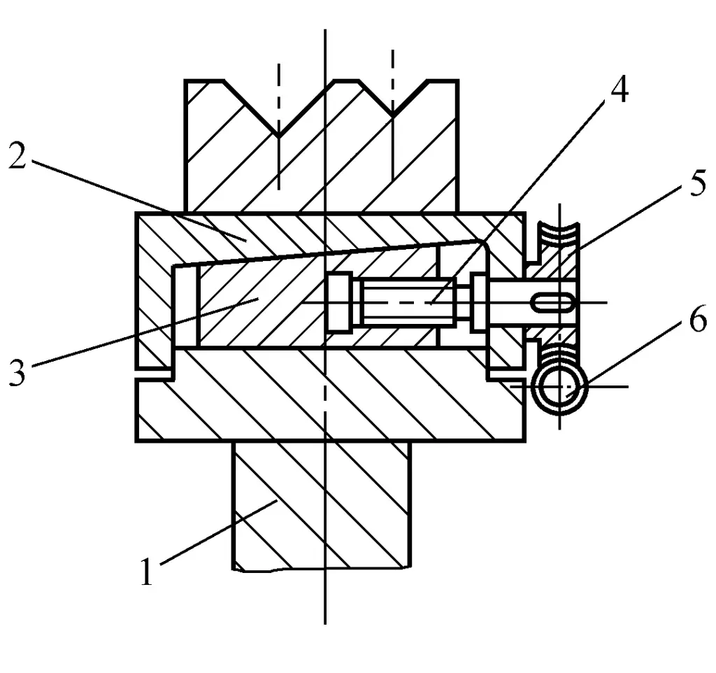
1—Workbench
2—Pad
3—Inclined wedge
4—Screw
5—Worm wheel
6—Worm
Since the deflection is greatest in the middle, the travel of the middle inclined wedge is also large, with the travel of the inclined wedges on both sides gradually decreasing. The different travel distances of each inclined wedge are achieved by the different transmission ratios of each worm gear transmission device. Each worm gear is on the same shaft, which can be driven by a handwheel or an electric motor, or by a servo motor, becoming a numerical control axis of a numerical control system.
Some inclined wedge protrusion devices have the direction of inclined wedge movement parallel to the length direction of the workbench, without the use of worm gear transmission, but directly driving the screw to move the inclined wedge of different slopes, thereby generating the required protrusions along the entire length of the workbench.
2. Die depth adjustment mechanism
In the three-point bending process introduced by Hammerle company in Switzerland, the depth of the inner bottom plate of the die affects the bending accuracy of the plate, therefore, a set of cylinder-wedge block mechanism is designed for adjustment, as shown in Figure 11.
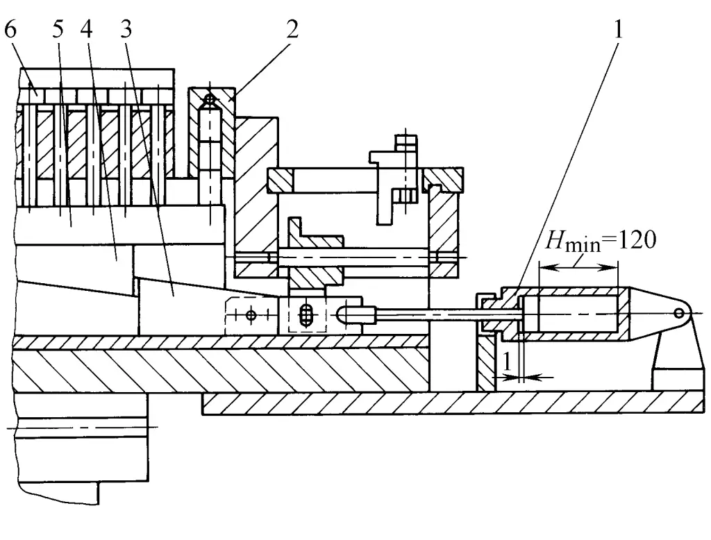
1—Cylinder
2—Small cylinder
3—Lower wedge block
4—Upper wedge block
5—Spacer block
6—Die bottom plate
When the piston rod of cylinder 1 moves to the right under the action of compressed air, it drives the lower wedge block 3 to also move to the right, pushing the upper wedge block 4 and the pad block 5, and overcoming the resistance of the piston of the small cylinder 2, causing the die base plate 6 to move upwards, at this time, the bending angle of the workpiece will increase; if the piston rod of cylinder 1 moves to the left, then under the action of the small cylinder 2, the die base plate 6 moves downwards, at this time the bending angle of the workpiece will decrease.
Due to the high stiffness of the wedge block mechanism, the adjusted bending angle during bending will not change. The precise positioning of the movement distance of the piston rod of cylinder 1 is achieved by a computer and a set of closed-loop systems.
Figure 12 shows a simplified diagram of the closed-loop control of the piston rod movement distance positioning mechanism. The computer issues instructions based on the required bending angle of the workpiece, causing the servo motor 1 to rotate, through the gear belt transmission system 3, 4, 5, via the friction disc 6 and the screw 2, it is converted into the linear motion of the nut 9.
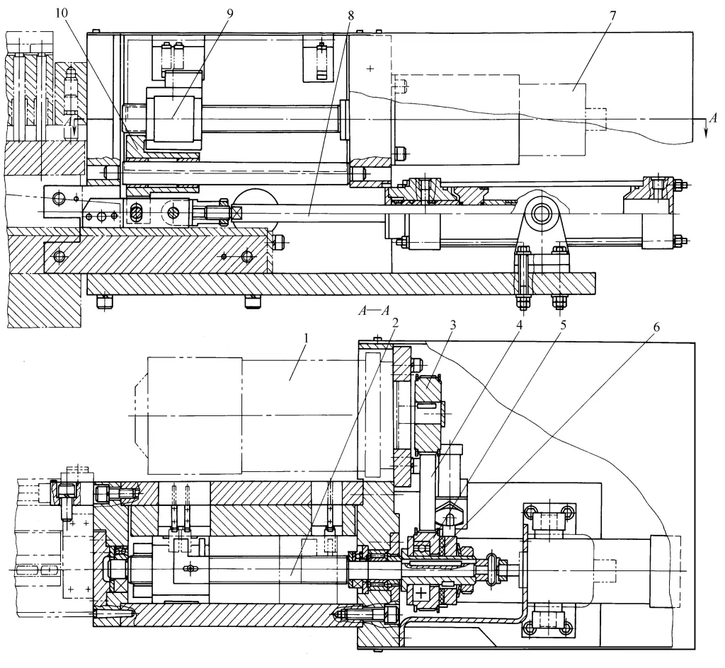
1—Servo motor
2—Screw
3, 5—Gear pulley
4—Gear belt
6—Friction disc
7—Digital disc
8—Piston rod
9—Nut
10—Bumper
The detection element installed at the right end of the screw, a digital disk 7, also rotates simultaneously, emitting feedback signals, which are sent back to the computer for comparison with the original input signal, forming a closed-loop control. This accurately defines the movement distance of the nut 9, and thus also defines the position of the bumper 10 and the connected cylinder piston rod 8.
In the three-point bending process, the change in plate thickness has little effect on bending accuracy, while the mechanical properties of the plate and the corresponding bending force mainly affect the bending angle.
For this reason, a sensor measuring the bending force is installed on the punch, and the bending force and its change characteristics during the bending process are stored in the computer’s mathematical model of the punch entering the depth of the die. When bending the next plate, it is compared with the measured data to calculate the correction amount for the depth of the punch entering the die.
3. Punch rapid clamping mechanism
The punch of a press brake is generally divided into several sections along its full length. In the past, many screws were used through a pressure plate to fix each section of the punch separately on the ram or punch seat, which was time-consuming and laborious during mold change and adjustment, greatly affecting production efficiency.
Now, a rapid clamping mechanism for the punch is adopted, using disc springs through a pressure plate to press the punch, and when changing the mold, hydraulic oil is pressed into the cylinder to push open the pressure plate, as shown in Figure 13. Several groups of disc springs 1 are distributed along the full length of the ram, pressing the punch 6 onto the mold seat 3 through the swinging lever 9 and the pressure plate 7. Since the lever 9 is fixed with a screw 8 through a spherical washer, the lever 9 can swing relative to the screw 8.
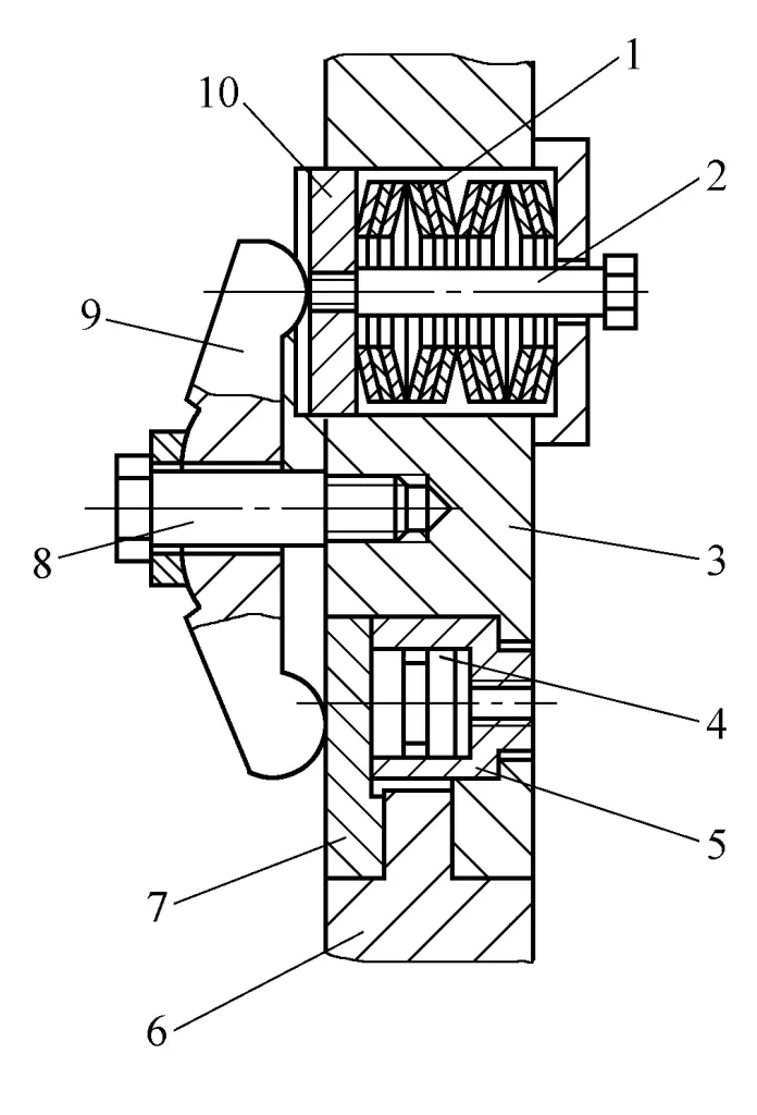
1 – disc spring
2 – screw
3 – mold base
4 – piston
5 – hydraulic cylinder
6 – punch
7 – pressure plate
8 – screw
9 – swinging lever
10 – disc
The upper end of the lever 9 extends into the groove of the disc 10 to prevent the lever 9 from rotating relative to the screw 8. The lower end of the lever 9 presses on the pressure plate 7. Each set of disc springs generates a pressure of 13.6kN on the surface of the pressure plate 7.
To release the punch, hydraulic oil can be pressed into the right chamber of the hydraulic cylinder 5 through the pipe, and the piston 4 pushes the pressure plate 7 to move left, causing the lever 9 to swing and press the disc springs. After replacing the punch, the right chamber of the hydraulic cylinder 5 drains the oil, and the disc springs press the lever 9 against the punch to fix it.
Figure 14 shows another type of quick clamping mechanism for the punch, where the punch can be clamped by filling the clamping hose 3 with hydraulic oil. To replace the punch, release the hydraulic clamping, open the safety pin 13, and the punch can be removed, which is very convenient and quick.
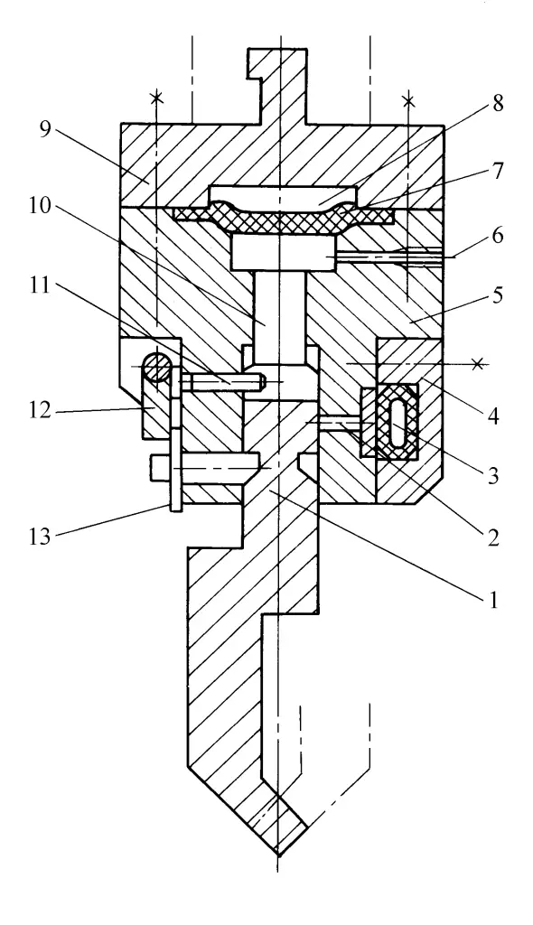
1 – Punch
2 – Clamping pin
3 – Hydraulic clamping hose
4 – Side cover
5 – Punch holder
6 – Lubricating oil inlet
7- Diaphragm
8- Hydraulic chamber
9- Cover
10- Thrust rod
11- Lock pin
12- Depth stop
13- Safety pin
Also, above each punch, there is a hydraulic cushion, which is composed of the hydraulic chamber 8 and the diaphragm 7. The hydraulic chambers are interconnected along their entire length, ensuring that the punch can uniformly pressurize the workpiece along the entire length of the workbench. When bending the workpiece, if the pressure on the punch is too high, pushing the diaphragm 7 upwards by 2mm through the thrust rod 10 causes the safety pin 13 to be pushed out, causing the depth stop 12 to rotate, triggering the limit switch, and sending a signal for the ram to return.
The widths of the segmented punches vary to allow for flexible combination, such as the punch combinations from the Trumpf company: two pieces of 25mm width, and one piece each of 30mm, 35mm, 40mm, 45mm, 50mm, making a total of 250mm as the basic combination, with 100mm on each end, and then adding extension blocks of 100mm, 200mm, 300mm, 500mm to form different length size combinations.
4. Automatic measurement of sheet thickness
The deviation in plate thickness can cause changes in the bending angle. For this reason, the CNC press brake of the German Mengele company is equipped with high-precision plate thickness measuring instruments. Before bending, the actual plate thickness deviation from the nominal plate thickness is input as a parameter into the CNC system to correct the depth of the punch entering the die.
This method is particularly suitable for thick plates with large thickness deviations. For example, for a 5mm thick steel plate, when using the automatic plate thickness measuring instrument, the maximum deviation of the bending angle is 1°, while without it, the deviation is about 6°.
The CNC press brake of the Swedish Pullmax company is equipped with a Sensomatic plate thickness sensor, which uses a sensing head fixed on the upper mold to directly contact the plate and measure its thickness. This measurement is input into the CNC system to correct the slide’s travel, changing the depth of the punch entering the die.
Experiments show that for a bent part with eight bending processes and a thickness of 5mm, with bending angles of 90° and 135°, the bending angle deviation for the four bends without plate thickness measurement is 4° at 90° and 5° at 135°. For the eleven bends with plate thickness measurement, the deviation of the bending angle does not exceed 0.3°.
Automatic measurement of bending angle and springback compensation
The mechanical properties of plate materials can often vary, and this difference in mechanical properties can cause changes in the bending angle, thereby affecting bending precision. For example, when bending at 90°, softer plate materials may approach an angle of 91°, while harder plate materials may only reach 89°, thus requiring correction.
The different mechanical properties of plate materials can also affect the springback rate, and adjusting for the springback rate is very labor-intensive. Therefore, automatic measurement and compensation of the bending angle and springback rate are very important for improving the precision of the bending angle.
The Belgian company LVD has developed an adaptive control system for automatically measuring bending angles and springback. When the touch probe contacts the plate material and moves with it, it continuously sends information about the bending angle to the control system to control the depth of the punch entry. To compensate for springback, a bending force measurement system is used.
Strain sensors are installed on the workbench. When the working stroke reaches the endpoint, the bending force decreases by 30%, and the punch automatically retracts to measure the bending angle again, calculates the springback amount, and sets a new pressing depth for re-pressing. With this adaptive system, trial bending is not needed, and adjustment time is greatly reduced. This system has been used on the company’s PPI and PPE series press brakes and is available as an optional accessory.
The CNC press brake of the French company Promecam also has a similar automatic bending angle measuring device. The angle sensor probe is made in a V shape, placed in the axial hole of the die, and fits against the working surface of the die. When the plate material is placed on the die, it also rests against the surface of the V-shaped sensor probe.
When the convex mold moves downward into the concave mold, the sensor generates a corresponding displacement and outputs relevant information through the angle detection mechanism. After being processed by the computer, the real-time angle value is displayed on the screen. When the displacement matches the set value, the CNC system issues a command to pause the supply of oil to the hydraulic cylinder, measures the angle change caused by the rebound of the plate material, and feeds it back to the CNC system for compensation.
The RT type sheet metal press brake produced by Beyeler Company of Switzerland adopts the new ROTAX rotary concave mold bending process, as shown in Figure 15. In this process, automatic measurement of bending angles and compensation for springback are realized. It uses two long rollers to replace the concave mold, with each roller having a flat surface. During bending, under the pressure of the convex mold, the two rollers rotate in the mold base to bend the sheet metal.
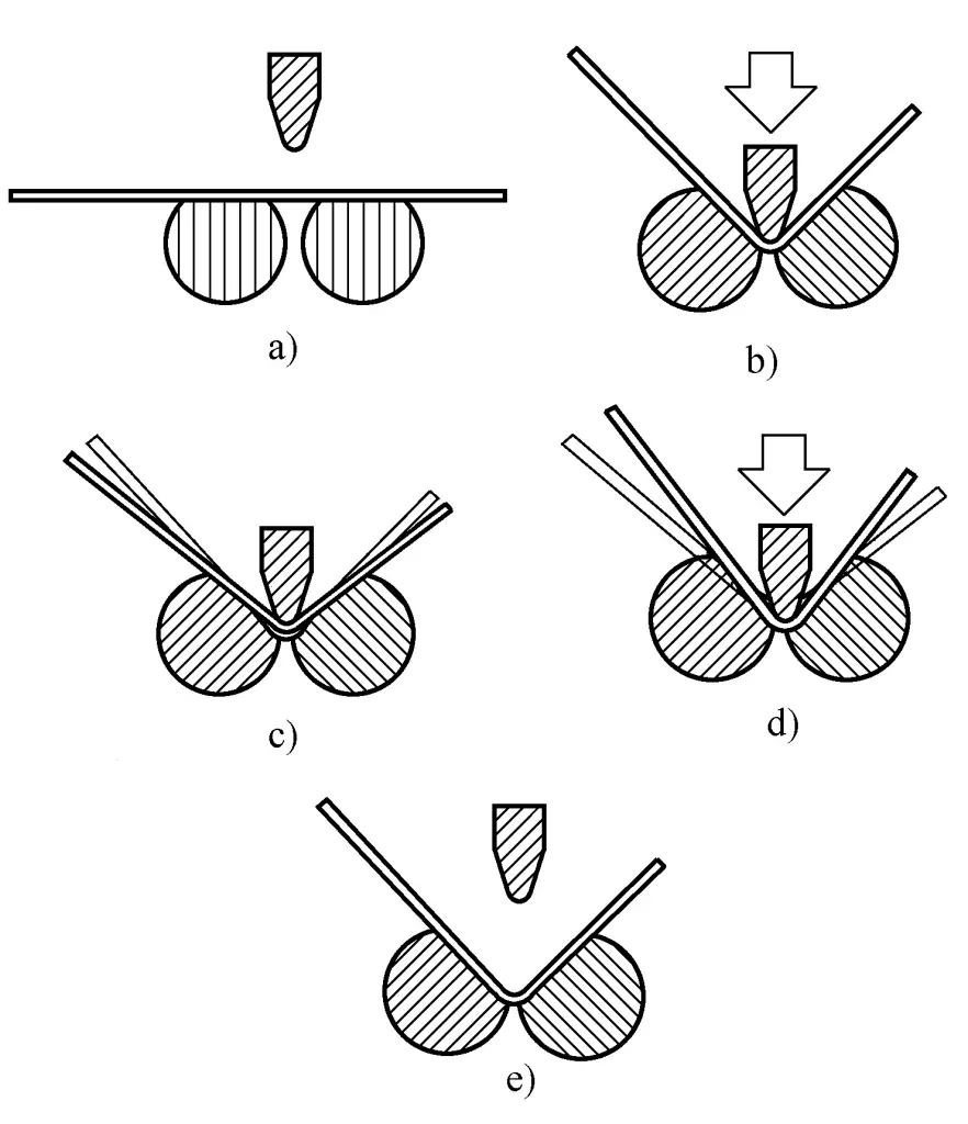
a) Start of the bending process
b) Bending to the programmed specified angle
c) Measuring the springback value
d) Correcting the springback value
e) End of the bending process
The actual bending angle can be conveniently measured by the rotation angle of the rollers. During the bending process, the measured angle values are continuously input into the CNC system. The two working hydraulic cylinders of the RT series press brake are each controlled by a servo valve, allowing the depth and parallelism of the convex mold entering the concave mold to reach an accuracy of 0.01mm.
Both long rollers are made up of sections of rollers, each 800mm in length, and each section can independently measure the bending angle and feed all the data back into the hydraulic compensation system of the press brake’s workbench, which is controlled by its own servo valve. Based on the measured angles, it can immediately act on a specific part of the bent piece for correction.
For the measurement of springback, as shown in Figure 15, when the bending reaches the set angle (see Figure 15b), record the pressure value at this time. The CNC system slightly releases the ram, reducing the pressure to 50% of the originally recorded pressure, and the ram stops (see Figure 15c). Then, measure the actual angle of the bent part again, thus obtaining half of the springback value. The CNC system can calculate the correction amount based on this value.
When continuing the bending, add this correction amount to finally obtain an accurate bending angle. Performing the above springback measurement and compensation increases the work cycle time by about 15%. Another advantage of the rotary die bending process is that the die does not scratch the plate or damage its surface.
IV. Backgauge Positioning and CNC System
Precise positioning of the plate on the press brake is very important, mainly relying on the backgauge. As the positioning needs to be frequently changed in the various processes of continuous bending of the plate, the backgauge must not only be able to position precisely but also change its positioning very quickly each time.
The backgauge positioning system of modern CNC press brakes generally uses digital AC servo motors driven, large lead precision ball screw transmission, and linear guide rails. The backgauge positioning system has six CNC axes: front and back (X0, X1), left and right (Z2, Z3), and up and down (R4, R5), as shown in Figure 16. These six CNC axes, plus two more CNC axes controlling the vertical movement of two working cylinders, Y1 and Y2, constitute what is generally called an eight-axis CNC.
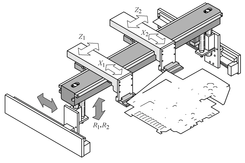
There are now dedicated CNC systems for press brakes available as commercial products, with the more famous ones being the DA65W, DA66W from the Dutch company Delem, and the DNC system from the Swiss company Cybelec, which generally have between 3 to 8 CNC axes.
V. Front Support and Robot
During the bending process of sheet metal, the sheet metal will gradually warp as the bending progresses. If not properly supported, the weight of the sheet metal will cause the bent parts to deform. In the past, this was supported by the operators, which was very labor-intensive and unsafe.
Modern sheet metal press brakes use a follow-up front support that automatically supports the sheet metal as it warps during bending. There are two types:
1. The floating type is supported by a cylinder under the front support, which can rise as the sheet metal warps. The air pressure should be adjusted to only support the sheet metal without causing additional deformation.
2. In the servo type, the sheet metal presses down on the support pin on the front support. When the sheet metal lifts, the support pin sends a signal, and the hydraulic servo mechanism controls the front support to rise synchronously. Using specially designed robots to automatically grip and operate the sheet metal is the most advanced.
The ASTRO100NT automatic bending unit produced by Amada Company of Japan includes a five-axis bending robot, which can hold the sheet metal on the press brake to complete the bending process. As the shape of the bent parts changes, the bending robot continuously changes the gripping position. After all bending processes are completed, the bending robot hands over the bent parts to the loading and unloading robot, which orderly stacks the finished workpieces on the product rack.
The CNC press brakes produced by Jiangsu Jinfangyuan Company and Yangli Company can be equipped with bending robots from Kuka Company of Germany. Kuka produces more than a dozen models of bending robots, divided into light load, medium load, heavy load, and super heavy load categories.
The robot is equipped with Bend Tech Pro bending software, which can generate a Windows-style process list and tool list offline while production is underway. The carrying range of Kuka bending robots ranges from 16kg to 210kg. It can not only undertake bending work but also change molds, and can be used for laser cutting, loading and unloading, and stacking.
VI. Types and Technical Parameters of Press Brakes
The model code of domestic press brakes, such as W67Y-63/2500, means:
- W – plate press brake code.
- 67 – a general press brake, 68 represents a plate bending shearing machine, and 69 represents a three-point press brake.
- Y – hydraulic transmission, while K indicates numerical control.
- 63 – the nominal force of the press brake as 630kN.
- 2500 – the length of the worktable is 2500mm.
Some manufacturers use uppercase English letters after W to indicate different types, such as WC, WB, WE, WMZ, WX, etc. If a number n is added before the model, it indicates n machines linked together, such as 2-W67Y-500/6000 represents 2 press brakes with a nominal force of 5000kN and a worktable length of 6000mm linked together.
VII. Edge Folding Machine
The working characteristic of the edge folding machine is that the sheet metal is clamped by the upper and lower pressing molds, with only the part to be folded extending out at the front of the sheet metal, and the folding is done by the folding beam. It is mainly used in various industrial sectors to manufacture thin metal sheet boxes, cabinets, and boxes, etc.
The schematic diagram of the structure of the edge folding machine is shown in Figure 19. The frame is composed of two side columns 1, the sheet metal to be folded is placed on the fixed crossbeam 3, the movable crossbeam 2 moves from top to bottom to press the sheet metal, and then the folding beam 4 rotates clockwise to bend the edge of the sheet that extends outside the mold of the movable and fixed beams into a circular arc equal to the mold corner. After the folding is completed, the folding beam 4 rotates counterclockwise back to its original position, the movable crossbeam rises, and releases the workpiece.
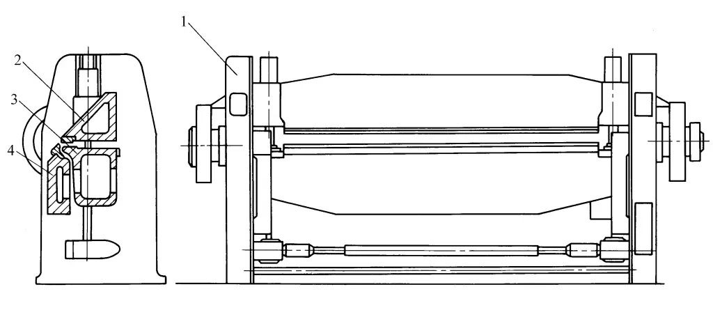
1—Column
2—Movable crossbeam
3—Fixed crossbeam
4—Folding beam
The transmission of the folding machine has two types: hydraulic and mechanical. The technical parameters of the folding machine produced by Xinzhou Forging Press Machine Tool Company are shown in Table 3.
Table 3 Technical parameters of W62 series folding machine
| Model W62 | Plate size (thickness × width) /mm | Minimum folding length at maximum thickness /mm | Minimum folding radius at maximum thickness /mm | Upper beam stroke /mm | Motor Power/kW | Weight /t | External dimensions (length × width × height)/mm |
| 2.5×1500 | 2.5×1500 | 12 | 2.5 | 200 | 4.1 | 1.6 | 2590×900×1300 |
| 2.5×2000 | 2.5×2000 | 12 | 2.5 | 200 | 5.5 | 3.1 | 3245×855×1400 |
| 2.5×2500 | 2.5×2500 | 12 | 2.5 | 200 | 5.5 | 4.15 | 3757×955×1400 |
| 4×2000A | 4×2000 | 30 | 4 | 200 | 8.5 | 4.2 | 3395×1485×1500 |
VIII. Four-side folding machine
The four-side folding machine was developed in 1977 by the Italian company Salvagnini as a new type of sheet metal folding equipment, making it the ideal device for processing box-shaped panel parts. Since then, various types of four-side folding machines have been developed by countries around the world, widely used in various production departments.
1. Working principle
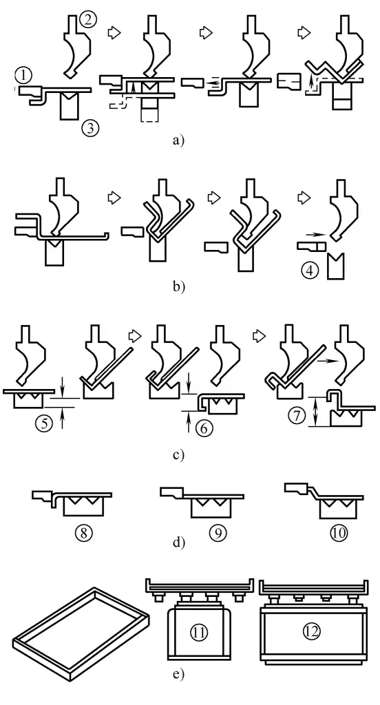
As shown in Figure 20, the hydraulic cylinder drives the upper pressing mold 2 to move vertically downward, pressing the sheet metal onto the lower pressing mold 1, with only the front end of the sheet metal extending out for the part to be folded. Both the upper folding mold 4 and the lower folding mold 5 are installed on the C-shaped mold base 3, which is also driven by a hydraulic cylinder to move vertically up and down.
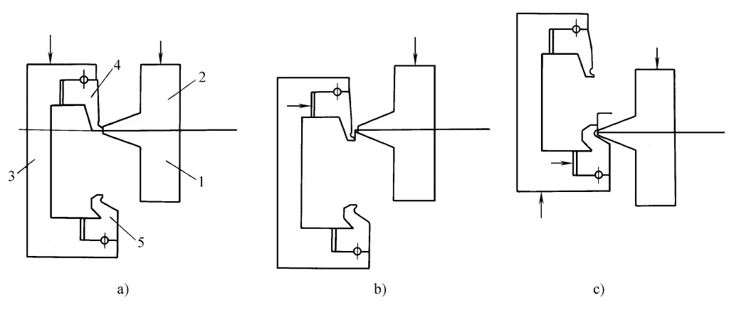
1—Lower pressing mold
2—Upper pressing mold
3—C-shaped mold base
4—Upper folding mold
5—Lower folding die
When moving downwards, the upper folding die folds the plate downwards, as shown in Figures a and b, while moving upwards, the lower folding die folds the plate upwards, as shown in Figure c.
In addition, the C-shaped die holder can also move left and right. After the upper and lower folding dies fold the plate to a certain angle, the C-shaped die holder moves horizontally to the right, further bending the plate into a sharper angle. Since the plate itself remains stationary in the horizontal plane during the folding process, it eliminates the complex movement of the plate in general press brakes, achieving higher folding precision and facilitating automated operations.
2. Structural Overview
The four-side folding machine consists of a bi-directional folding mechanism, a positioning worktable, an operating machine, a loading and unloading device, a CNC system, and an electrical control system.
The plate to be folded usually has notches punched out at the four corners. When a vacuum suction cup delivers a single sheet of plate to the track of the loading device, a magnetic conveyor belt then transports the plate to the positioning worktable for positioning. After positioning and clamping, the operating machine carries the clamped plate to the bi-directional folding mechanism for folding according to instructions.
For rectangular plates, the short sides are usually folded first. With each bend, the operating machine advances the plate a given distance. After completing all the folding operations for the first short side, the operating machine retracts with the plate, and a rotating mechanism rotates the plate 180° around the press rod axis in the horizontal plane to start folding the second short side. Subsequently, it rotates in sequence to complete the folding of the two long sides.
3. Bi-directional Bending Mechanism
As shown in Figure 21, the folding ram 1 is driven by two hydraulic cylinders 7 suspended from the rear and swings up and down around the eccentric shaft 9 at the back. When swinging upwards, the lower folding die 2 folds the plate upwards, and when swinging downwards, the upper folding die 6 folds the plate downwards. The maximum angle for both upward and downward folding generally does not exceed 85°. If a larger bending angle is required, hydraulic cylinder 8 pushes the rack to rotate the gear 10 on the eccentric shaft 9, driving the eccentric shaft 9 to rotate, moving the folding ram 1 forward for horizontal folding to increase the bending angle.
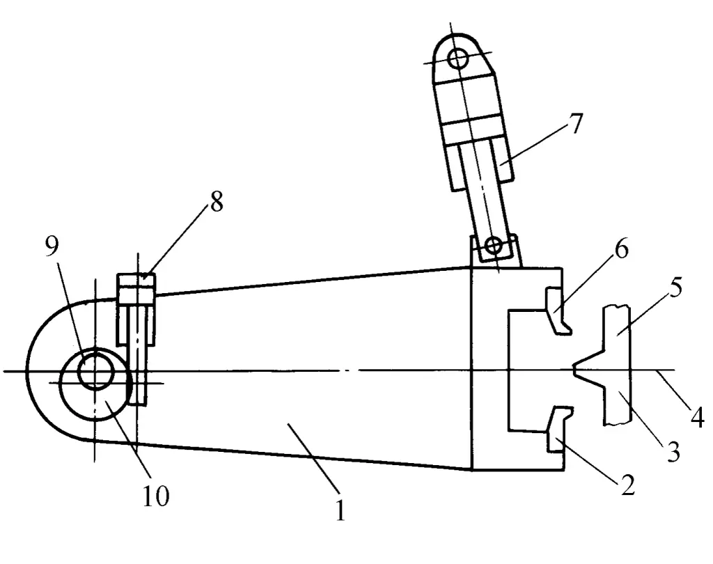
1-fold edge ram
2-fold edge mold
3-press mold
4-sheet metal
5-top press mold
6-top fold edge mold
7, 8-hydraulic cylinder
9-eccentric shaft
10-gear
The two hydraulic cylinders 7 are each controlled by a proportional speed control valve and use a grating to detect the displacement of the piston rod, forming a closed-loop control system to achieve the synchronous movement of the two hydraulic cylinders and the position control of the stroke endpoint. Below the hydraulic cylinder 8, there is a mechanical stopper, which is adjusted by a servo motor according to program instructions, thus precisely controlling the stroke of the piston rod of the hydraulic cylinder 8 and the horizontal displacement of the fold edge mold, to ensure the final accuracy of the bending angle.
4. Positioning mechanism
As shown in Figure 22, the operating machine pushes the sheet metal 4 forward with the rear stop block 3 mounted on it, until it abuts against the front stop block 1 (there are three sets of front stop blocks, one set can be chosen according to the size of the sheet metal 4), completing the positioning of the sheet metal in the front and rear direction. The right stop block 2 and the left stop block 5 are each driven by a servo motor through a ball screw, moving towards the center, to complete the positioning of the sheet metal in the left and right direction.
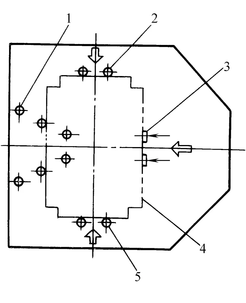
1 – Front stop block
2 – Right stop block
3 – Rear stop block
4 – Sheet metal
5 – Left stop block
5. Operating machine
The clamping disc of the operating machine is driven by a hydraulic cylinder, clamping the sheet metal on the turntable. The rotation mechanism is driven by a servo motor through a timing belt and a worm gear pair, rotating the turntable. A high-pulse photoelectric encoder is installed on the axis of the turntable, forming a closed-loop control system, with a rotation accuracy error of no more than 0.02°.
6. Scalable compression mold
As shown in Figure 23, when folding, it is necessary to first press the entire length of the sheet with the upper compression mold. To accommodate sheets of different lengths, the upper compression mold consists of several modules of different lengths. The center module 2 is connected to the vertical hydraulic cylinder above and can be lifted upwards. There are several intermediate modules of different lengths on both sides, and there is one corner module at each end.
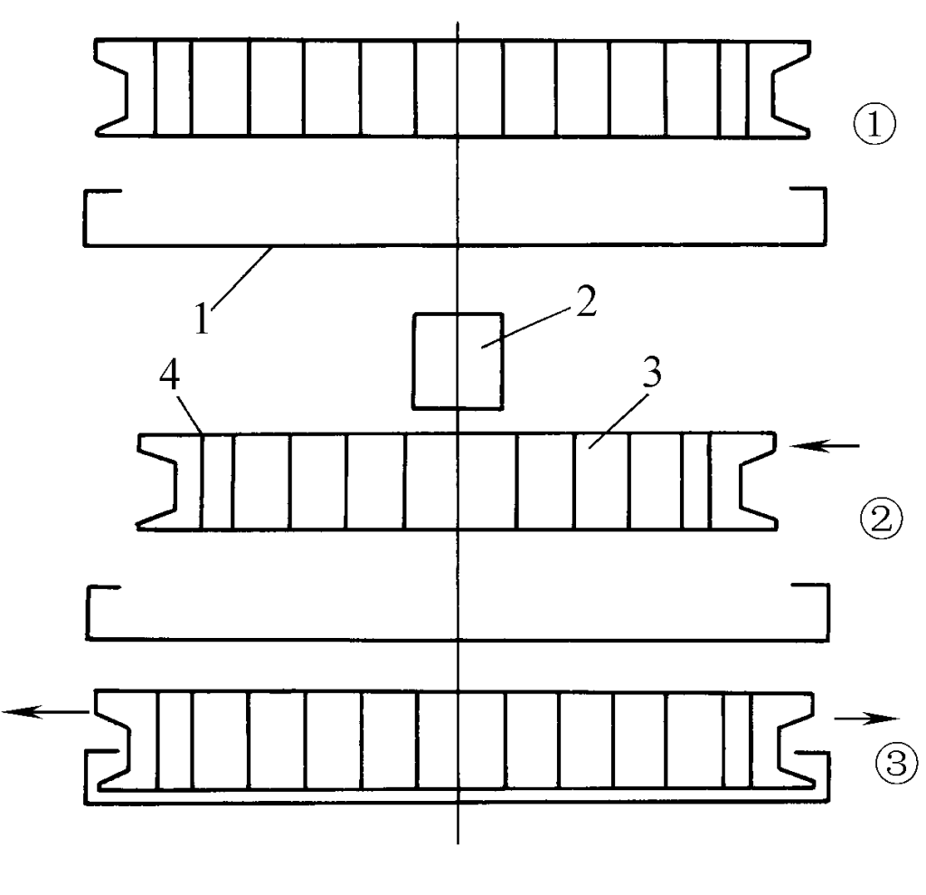
1—Workpiece
2—Center module
3—Side module
4—Corner module
When the box-shaped workpiece has formed an inward flange, to remove the upper compression module, the center module can first be lifted upwards with the hydraulic cylinder, and then the two side modules are pushed by the two horizontal hydraulic cylinders on both sides, causing the intermediate modules and corner modules to move towards the center. This allows for easy removal and the opposite process for installation, so that the total length of the assembled compression mold matches the length of the box-shaped panel workpiece.
7. Main technical parameters
The main technical parameters of the W63K-2×2000 type four-side press brake are as follows:
- Sheet thickness: 0.5~2mm.
- Maximum blank size of the sheet: 1200mm×2000mm.
- Bending angle: 5°~120°.
- Minimum bending radius: 1mm.
- Minimum height of the bending edge: 12mm.
- Maximum height of the part edge: 160mm.
- Maximum number of bends per side of the sheet: 5.
- Number of control axes in the CNC system: 7.
Features of the four-side press brake
(1) The biggest advantage is that the sheet does not need to be handled during the bending process, greatly improving productivity and automation level.
(2) No need to change the upper and lower bending dies. This saves the time of changing molds and eliminates the need for multiple molds.
(3) For the already punched sheet metal, positioning is done using the cut of the sheet metal, completing multi-side bending in one positioning, eliminating the accumulated positioning error caused by multiple repositioning, resulting in high bending accuracy.
(4) Advanced structural design, with tool dynamic compensation, angle accuracy of ±30′, and the parallelism of two opposite sides after bending is ±0.1mm/m.
(5) During the processing, the feeding and rotation of the sheet metal are continuously and automatically carried out, therefore the processing time is much shorter than other bending centers, especially for box-shaped parts.
(6) Strong software capabilities, capable of completing the automatic programming of the presser and the automatic generation of the bending program, significantly shortening the preparation work.
(7) Due to the different bending mechanisms, it can complete bending processes that other bending centers cannot, thus allowing for a more simplified and rational product structural design.
The P4-2516 model multi-side panel bender for metal sheets, exhibited by Salvagnini in 2005, is especially suitable for multi-variety, small-batch production. When changing workpieces, there is no need to change molds, with short bending time and high efficiency.
For example, bending a piece with 4 times 90° positive bends only takes 28 seconds: bending a complex piece with 2 times 90° positive bends, 8 times 90° negative bends, and 4 times 45° positive bends only takes 44 seconds. The maximum processing width of the sheet is 1500mm, the maximum length is 2695mm, the maximum diagonal length is 2800mm, and the maximum thickness is 2.5mm (carbon steel), 2.0mm (stainless steel), and 3.0mm (aluminum): the maximum bending length of the finished workpiece is 2500mm, and the maximum bending height is 165mm. It has a self-correction function, which can automatically calculate the correction value according to the material, thickness, and angle of different sheet metals.
IX. Automated Bending Device
The unmanned CNC sheet metal bending unit, combined with a CNC press brake machine, forms an integrated whole, replacing manual continuous uninterrupted work, easy to program, especially suitable for medium and small batch processing of small parts. The device has good rigidity, high precision, and simple installation and adjustment.
The bending robot can automatically grab and process sheet metal, automatically bend, and automatically stack the bent workpieces. The control system uses a teaching function, eliminating the need for complex programming.
The TruBend Cell5000 automated device produced by Trumpf, with its BendMaster for loading and unloading bending parts, can relieve operators of many heavy tasks, especially when handling large workpieces weighing up to 100kg, with most of the work completed by the machine. The TruBend Cell7000 is suitable for the automatic bending of small workpieces in a compact form, especially with its lightweight backgauge system and modern hydraulic drive design, making it the fastest bending unit among similar products.
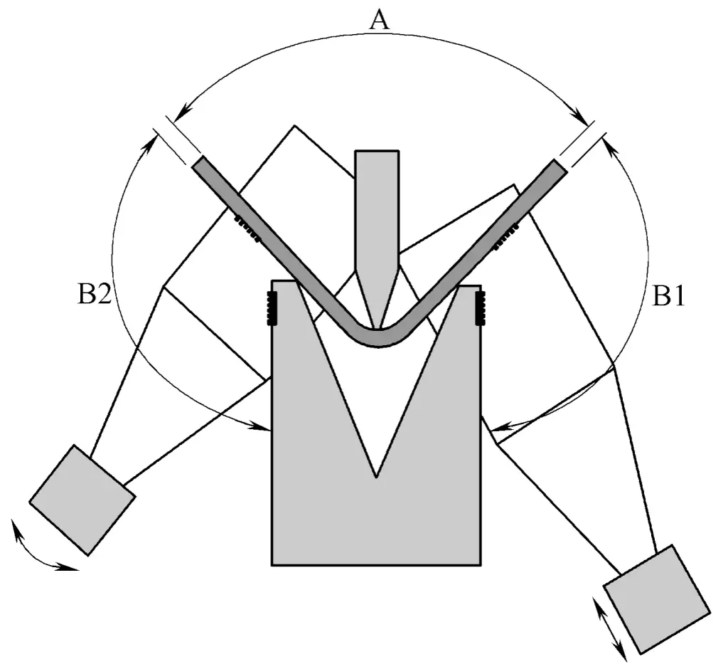
A laser online angle measurement system in press brakes, using a laser beam to detect the angle of the bend in real-time, to ensure precise bending effects, as shown in Figure 24.
