Hydraulic Cylinders: Working Principles & Types
What powers the heavy machinery used in construction and manufacturing? Hydraulic cylinders play a pivotal role, transforming hydraulic energy into…
How does a hydraulic press exert such immense power? From nominal force to worktable dimensions, understanding these parameters is crucial for anyone involved in machining or metalworking. This article delves into the essential technical aspects that define a hydraulic press’s capacity and performance, providing insights that can help you select the right press for your needs. Read on to uncover the specifics of how each parameter impacts the machine’s efficiency and functionality.
The basic parameters are the fundamental technical data of the hydraulic press, determined by the process use and structural type of the hydraulic press. They reflect the working capacity and characteristics of the hydraulic press, and essentially set the outline dimensions and total weight of the body. The basic parameters are the main basis for users when purchasing.
Now, taking the three-beam four-column hydraulic press as an example, the basic parameters of the hydraulic press are introduced.
The nominal force is generally the main parameter of the hydraulic press, reflecting its main working capacity. The nominal force is the maximum working pressure that the hydraulic press can nominally exert, numerically equal to the product of the maximum pressure of the liquid and the total working area of the working pistons (rounded to an integer).
To fully utilize the equipment, meet the process requirements, and save high-pressure liquid, generally large and medium-sized hydraulic presses divide the nominal force into two or three levels. Hydraulic presses driven directly by pumps do not need to be structurally divided into pressure levels.
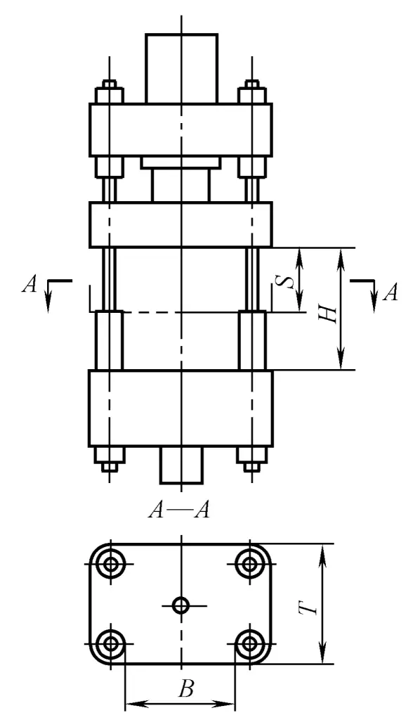
The maximum clearance distance H refers to the distance from the surface of the worktable to the underside of the moving crossbeam when it stops at the upper limit position, as shown in Figure 1-1-6.
The maximum clearance distance reflects the size of the working space in the height direction of the hydraulic press. It should be determined based on the height of the mold (tool) and corresponding spacer, the size of the working stroke, and the space required for inserting blanks and removing workpieces, among other process factors.
The maximum clearance distance has a significant impact on the overall height of the hydraulic press, the length of the columns, the stability of the hydraulic press body, and the height of the installation workshop. Therefore, the height of the press should be minimized as much as possible while meeting the process requirements, in order to reduce its cost.
The maximum clearance distance for a single-arm hydraulic press is the distance from the underside of the press head to the surface of the worktable, as shown in Figure 1-1-7.
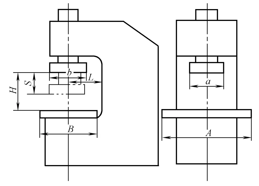
The maximum stroke S refers to the distance from the lower surface of the column guide sleeve of the moving crossbeam at the upper limit position to the upper surface of the column limit sleeve, which is also the maximum distance the moving crossbeam can move.
The maximum stroke should be determined based on the maximum working stroke required during the workpiece forming process, as it directly affects the length of the working cylinder and return cylinder and their pistons, as well as the overall height of the frame.
The worktable is generally fixed on the lower crossbeam, where molds or tools are placed. The size of the worktable refers to the effective dimensions available on the surface of the worktable, such as B×T in Figure 1-1-6, or A×B in Figure 1-1-7. The size of the worktable depends on the planar dimensions of the mold (tool) and the arrangement of the process.
Large and medium-sized forging or thick plate stamping hydraulic presses often have a movable worktable, the stroke of the movable worktable and the nominal force of the pushing cylinder are related to the need for mold replacement and the method of process operation.
In addition to the size of the worktable, in some four-column hydraulic presses, the center distance of the columns (wide side and narrow side) is also used as a parameter. The single-arm hydraulic press is open on three sides in the plane, and the parameter that affects the size of the workspace on the plane is the throat depth, which is the distance from the center of the press head of the single-arm hydraulic press to the inner surface of the frame, as shown in Figure 1-1-7 as L.
When calculating the force required for the return, consider the weight of the moving parts, the force required during the return process (such as mold pulling force, lifting chopper, etc.), the resistance of the working cylinder to discharge fluid, the friction at the seals of the cylinders, and the friction at the guide of the moving crossbeam. The return force is achieved by the high-pressure fluid pushing the annular area of the piston ring in the lower chamber of the piston cylinder or by a separately set return cylinder.
Can be divided into working stroke speed, idle stroke (filling stroke) speed, and return speed.
The speed of the working stroke should be determined according to different process requirements, its range of variation is large, and it directly affects the quality of the workpiece and the power demand on the pump. Forging hydraulic presses require a high working speed, reaching 50~150mm/s, while the working stroke speed of four-column universal and trimming hydraulic presses is 10~15mm/s, and that of electrode extrusion hydraulic presses is only about 3mm/s.
The power of a pump directly driven hydraulic pump is proportional to the speed of the working stroke. The speed during idle and return can generally be higher to improve productivity. However, if the speed is too fast, it will cause water hammer and vibration when stopping or reversing.
In many processes performed on hydraulic presses, eccentric loads often occur, which happen on both the wide and narrow sides of the hydraulic press. The maximum allowable eccentricity refers to the maximum eccentricity allowed when the resistance to deformation of the workpiece approaches the nominal force. When selecting a hydraulic press, this eccentricity should be considered based on the characteristics of the process.
Some hydraulic presses (such as die forging and stamping hydraulic presses) often have ejectors installed in the lower crossbeam for ejecting workpieces or during drawing. The force and stroke of the ejector are entirely determined by the process requirements.
For various hydraulic presses with different structural forms and different process purposes, there are different basic parameters. The machinery industry department in our country has established various standards for hydraulic press forms and basic parameters for different process purposes, such as single-arm stamping hydraulic press JB/T2098-2010, four-column universal hydraulic press (JB/T9957.2-1999), trimming hydraulic press (JB/T1881-2010), etc.