Metal Bending Processes: Equipment, Parameters, and Troubleshooting
How do flat sheets become curved parts? Metal bending is key. This article unveils the tools, techniques, and tricks behind…
How do industrial robots master precision and versatility? In this article, we explore the intricate components and mechanisms of these engineering marvels. From the powerful manipulators to the sophisticated drive systems, discover how robots perform complex tasks with remarkable accuracy. You’ll learn about the structure of robotic arms, the functionality of different joints, and the technologies behind their movements. Dive in to understand the engineering behind these indispensable tools of modern manufacturing.

Industrial robot systems generally consist of four parts: the manipulator (body), environment, tasks, and controller, as shown in Figure 1.
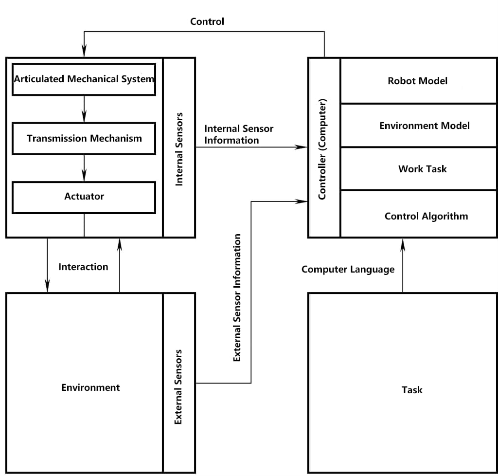
The environment refers to the working environment of the robot, including the work object and some obstacles. The robot must prevent interference with these objects during its movement.
The task refers to the work that the robot needs to complete, such as welding, painting, or handling, etc. It can usually be defined as the difference between two states of the environment, and needs to be described and stored in the robot controller with appropriate language or programs.
The controller is used to receive information detected by internal and external sensors of the robot, process it, and generate control signals according to a certain control program, driving the various joints of the robot body, thereby completing the given task. The robot body is the mechanical mechanism that performs the task, consisting of a set of interconnected motion mechanisms including arms, joints, and end effectors.
In practical engineering, the robot body is also known as the manipulator, robotic arm, or mechanical hand, etc. Most robot bodies are jointed mechanical structures with several degrees of freedom. Welding robots usually have 6 degrees of freedom, 3 of which guide the end tool to the required position, and the other 3 are used to control the posture of the tool.
In a broad sense, robot mechanisms can generally be regarded as a type of rod mechanism, including parts such as arms, wrists, claws, and walking mechanisms. For welding robots, their body structure mainly includes the arm and wrist parts.
For a free rigid body, it has 6 degrees of freedom in three-dimensional space, as shown in Figure 2. To complete any spatial operation, the robot also needs 6 degrees of freedom.
The movement of the robot is a combination of the movements of the arm and wrist. Usually, the arm part has 3 joints, which are used to change the position of the wrist reference point, called the positioning mechanism; the wrist part also has 3 joints, usually these 3 joint axes intersect, used to change the posture of the end tool, called the orientation mechanism. Therefore, the entire robot can be seen as the positioning mechanism connected to the orientation mechanism.
The arm of the robot is the part that directly performs the operation, and its structure will greatly affect the capability of the robot. Generally speaking, the arm is composed of rods and the joints (kinematic pairs) connecting them. A joint has one or several degrees of freedom.
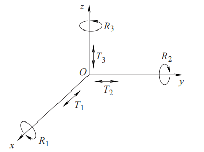
The so-called degree of freedom is an indicator of the flexibility of robot movement, meaning the number of independent individual movements. The degrees of freedom that can produce active motion by the actuator are called active degrees of freedom, and those that cannot produce driving force are called passive degrees of freedom. Table 1 shows the symbols and motion directions of representative single-degree-of-freedom joints.
Table 1 Single Degree of Freedom Joints
| Name | Symbol | Example |
| Translation | 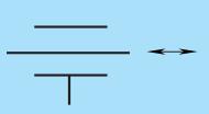 | 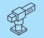 |
| Rotation | 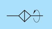 |  |
| Rotation ① | 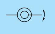 | 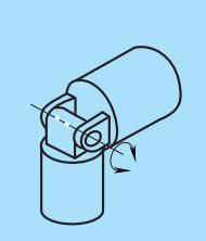 |
| Rotation ② | 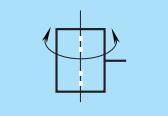 |
The methods of constructing members and joints can be roughly divided into two types. From the overall view of the arm, the members and joints that make up the arm are serially connected, known as serial member robots or open-chain robots, while those connected in parallel are called parallel member robots or closed-chain robots. In Figure 3, examples of the degrees of freedom of serial and parallel member robotic hands are given. In fact, most robotic hands are of the serial member type.
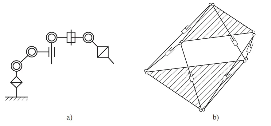
a) Serial member type
b) Parallel member type
The method of constructing degrees of freedom greatly affects the robot’s range of motion and operability, among other performances. For example, a spherical joint is a three-degree-of-freedom joint that can move in any direction, which can easily determine a posture suitable for the task. However, due to the limitations of the actuator, it is difficult to fully realize this function. Therefore, robots usually connect three single-degree-of-freedom mechanisms in series to achieve these three degrees of freedom.
Using such a serial connection method, even with the same three degrees of freedom, there are many different combinations of degrees of freedom, each with different functions.
For example, there are many specific construction methods for a 3-degree-of-freedom wrist mechanism. Considering the conditions of having translational and rotational degrees of freedom on the x, y, and z axes, if there is no offset between adjacent links, and the axes of adjacent joints are either perpendicular or parallel to each other, there are a total of 63 kinds. Additionally, with the inclusion of three degrees of rotation, a 6-degree-of-freedom arm has as many as 909 ways of constructing degrees of freedom.
Therefore, it is necessary to determine the effective way of constructing degrees of freedom based on criteria such as the requirements of the target operation.
The main purpose of the arm is to position in three-dimensional space, for which, as mentioned earlier, three degrees of freedom are necessary. If considering the combination of translational, rotational, and rotational degrees of freedom, there are a total of 27 ways to construct degrees of freedom. However, based on its motion form, representative ways of constructing degrees of freedom can be divided into the following four types:
The cylindrical coordinate type robot, seen in Figure 4, is composed of a combination of one rotation and two translations; the spherical coordinate type robot, seen in Figure 5, is formed by a combination of rotation, rotation, and translation.
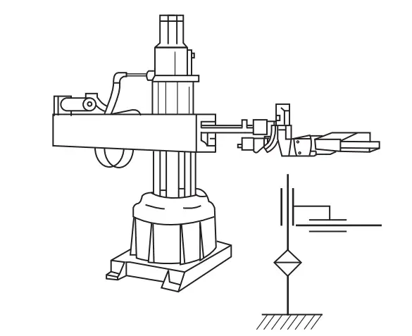
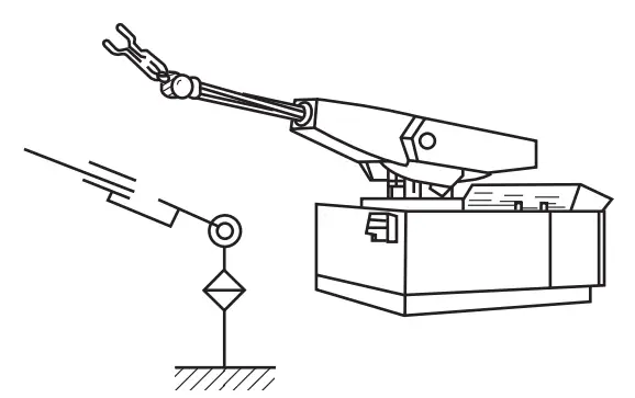
These two types of robots, having a central rotational degree of freedom, both have a large range of motion, and their coordinate calculations are relatively simple. The world’s first practical industrial robots, “Versatran” and “Unimate,” adopted cylindrical and spherical coordinate mechanisms, respectively.
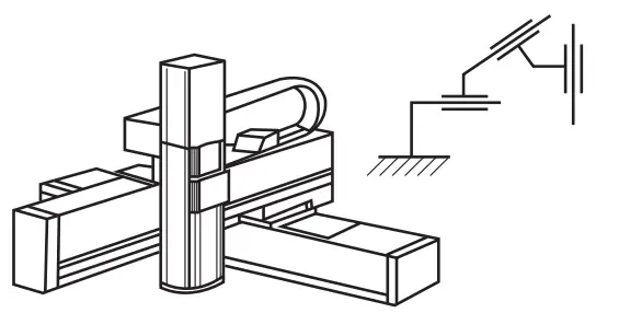
The Cartesian coordinate type robot (seen in Figure 6) has degrees of freedom that are independent along the x, y, and z axes, with a simple structure, high precision, and extremely simple coordinate calculation and control. However, its range of motion is not wide, making it difficult to achieve high-speed actions.
The articulated robot is mainly composed of rotational and rotational degrees of freedom, which can be seen as a structure imitating a human arm, with a link joint structure that has an elbow joint. In this case, the part from the elbow to the shoulder is called the upper arm, and the part from the elbow to the wrist is called the forearm. This structure is most effective for determining any position and posture in three-dimensional space. It has good adaptability to various tasks, but its disadvantage is that coordinate calculation and control are relatively complex, and it is difficult to achieve high precision.
The articulated robot, based on its method of constructing degrees of freedom, can be further divided into several categories.
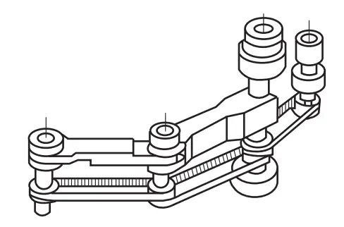
Figure 7 is a general arm, which adopts a structure of rotation, rotation, rotation degrees of freedom. The arm in Figure 8 uses a parallelogram link and mounts the actuator used for joint driving at the base of the arm.
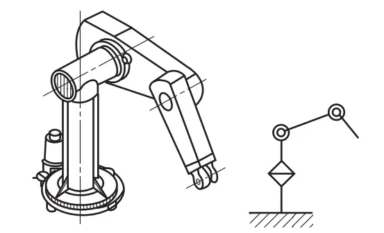
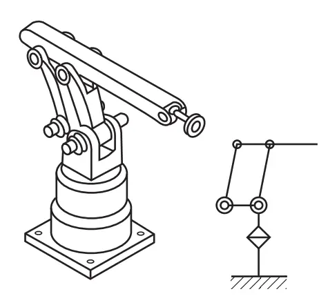
Figure 9 is called a SCARA robot (Selective Compliance Assembly Robot Arm), and the front-end structure of the arm adopts degrees of freedom that can move arbitrarily within a two-dimensional plane, so it has the characteristics of high rigidity in the vertical direction and low rigidity (compliance) in the horizontal direction.
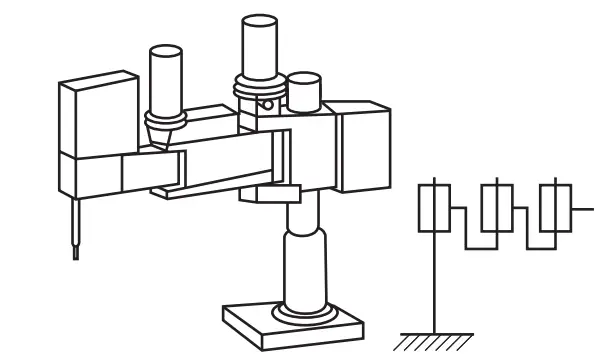
However, in actual operation, it is not mainly because of this special compliance property it possesses, but because it can more simply achieve actions on a two-dimensional plane, thus it is widely used in assembly operations.
The robot’s wrist is the connecting part between the arm and the end tool, used to change the tool’s position and orientation in space. The structure of the wrist is generally complex, directly affecting the robot’s dexterity. The most common wrist consists of two or three mutually perpendicular joint axes, with the first joint of the wrist being the robot’s fourth joint.
Figure 10 is a simple Pitch-Roll spherical wrist. Three bevel gears A, B, and C form a differential mechanism, with gears A and B connected to two drive motors via chain or belt transmission, using the speed difference and rotation direction of gears A and B to synthesize the tool’s rotation direction and speed.
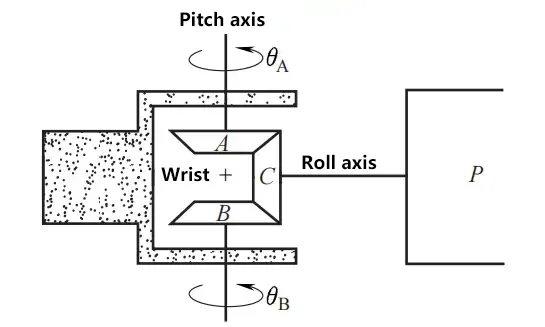
Figure 11 shows a schematic and transmission diagram of a 3-degree-of-freedom wrist, with three axes perpendicular to each other and intersecting at one point. Theoretically, this wrist can achieve any posture, but due to structural limitations on joint angles, it cannot achieve any posture. This type of wrist is the most common form in robots.
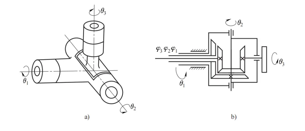
a) Schematic diagram
b) Transmission diagram
The main drives of robots are divided into hydraulic drive, pneumatic drive, and electric drive, etc.
The main advantage of hydraulic drive is its high power, simple structure, the elimination of reduction gear, direct connection with the driven rod, and quick response. Hydraulic servo drive has high precision, but requires an additional hydraulic source, and is prone to liquid leakage, hence hydraulic drive is mostly used in very high power robot systems.
Pneumatic actuators have simple energy sources and structures, but compared to hydraulic actuators, they have smaller power under the same volume conditions (due to lower pressure), and their speed is not easy to control, so they are mostly used in low-precision point control systems.
Electric actuators are the most widely used actuators at present. They have simple energy sources, a wide range of speed changes, high efficiency, and high speed and position accuracy, but they are often connected with reduction gears, making direct drive difficult. Electric actuators can be divided into DC, AC servo motor drive, and stepper motor drive.
The latter is mostly open-loop control, simple control but not high power, mostly used in low precision, low power robot systems. DC servo motors have many advantages, but their brushes are prone to wear and can easily form sparks. With technological progress, AC servo motors have been gradually replacing DC servo motors as the main actuators in robots in recent years.
DC servo motors have small rotational inertia, quick start and stop response, a wide range of speed changes, high efficiency, and high speed and position control accuracy.
DC servo motors have many advantages and a high cost-performance ratio, always being the standard motor for robot platforms. However, their brushes are prone to wear and can easily form sparks. Thus, brushless motors have been developed, using Hall circuits for commutation.
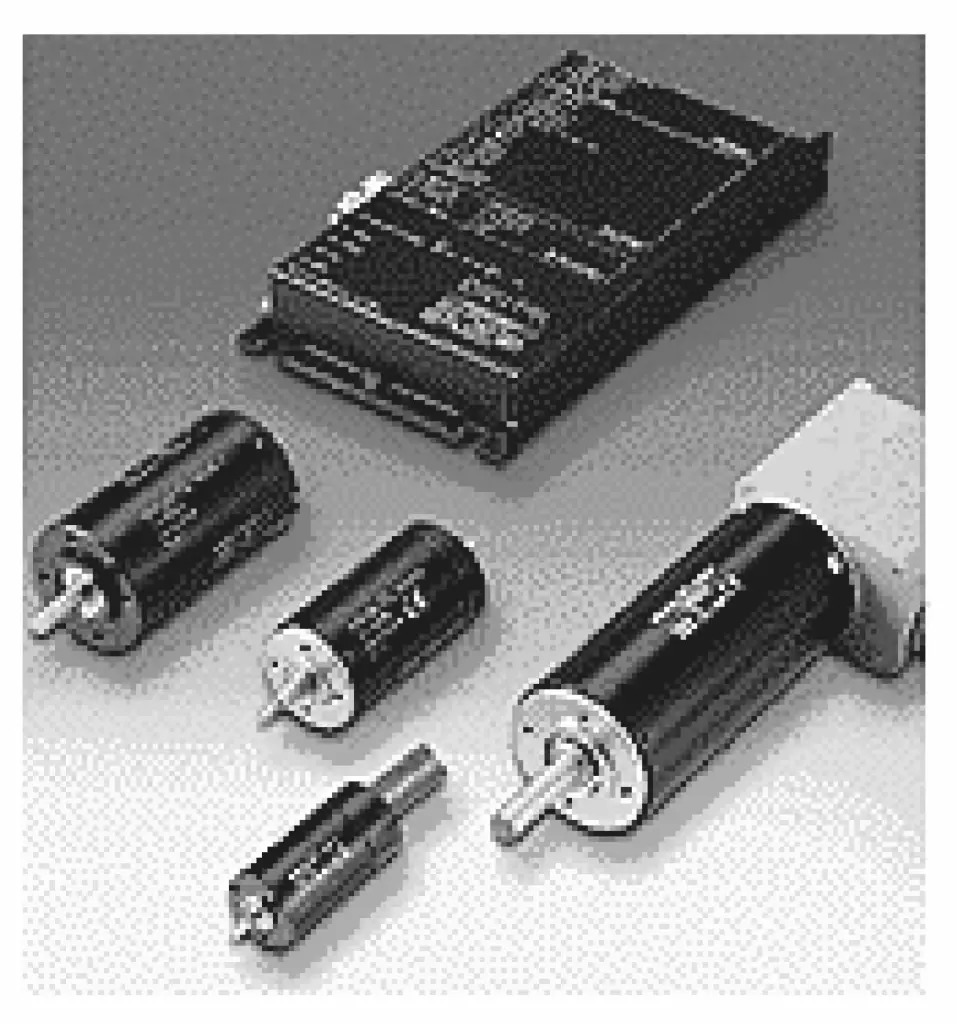
Figure 12 shows a DC servo motor and drive amplifier.
AC servo motors have higher power than DC servo motors, do not need brushes, high efficiency, and are easy to maintain, being the most widely used in industrial robots. Figure 13 shows an AC servo motor and drive amplifier.
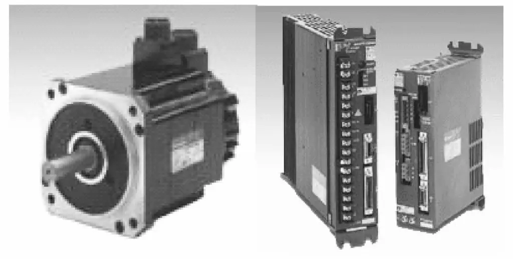
The main technical parameters of AC servo motors are similar to those of DC servo motors.
Stepper motors are a type of brushless motor, with magnets mounted on the rotor and windings mounted on the casing. Stepper motors are essentially low-speed motors, easy to control, capable of precise movements, with an optimal operating speed of 50~100r/min. Figure 14 shows a stepper motor and driver.
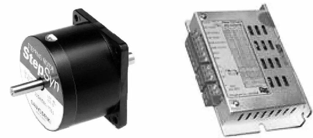
Stepper motor drives are mostly open-loop control, simple to control but not powerful, with good braking effects, but may experience step loss at very low speeds or under heavy loads, often used in low-precision, low-power robotic systems.
There are two types of joint drive methods: direct drive and indirect drive. The direct drive method directly connects the output shaft of the driver to the joint axis of the robot arm. The indirect drive method transmits the force of the driver to the joint through a reducer or steel wire rope, belt, parallel linkage, etc.
The advantage of direct drive is that there are fewer mechanical systems between the driver and the joint, thereby reducing the impact of non-linear factors such as friction, resulting in better control performance. However, on the other hand, in order to directly drive the arm’s joint, the output torque of the driver must be very large, in addition, the dynamics of the arm must be considered.
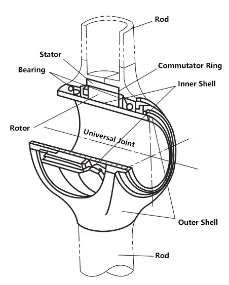
The torque motor developed in the 1980s, whose mechanical system mainly consists of bearings, can achieve excellent reverse driving capability (driving the output shaft of the driver from the joint side). An example of a joint structure using a torque motor for direct drive is given in Figure 15. Robots using such direct drive methods are usually called Direct Drive Robots (DD Robots).
Most robot joints are indirectly driven. For this type of indirect drive, the output torque of the driver is usually significantly less than the torque required to drive the joint, so a reducer must be used.
In addition, since the arm generally adopts a cantilever beam structure, the installation position of the driver driving the multi-degree-of-freedom robot joint will increase the load on the root joint driver of the arm. The solution to this problem can usually be achieved with the following simple drive mechanisms.
This method also places the driver far from the joint, as one of the means of remote driving. Chains and steel belts have good rigidity and can transmit large torque, often used in SCARA type robots. The toothed belt drive method is shown in Figure 16.
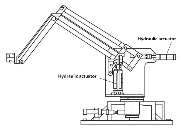
The feature of this method is that it can install the driver at the base of the arm, and this structure makes the coordinate transformation calculation extremely simple, an example is shown in Figure 17.
As mentioned earlier, in the process of driving robot joints with electric motors, considering the driving torque and control precision, a reduction mechanism is generally required. Common reduction mechanisms used in robots include harmonic reducers and RV cycloidal pinwheel reducers, and helical transmission is also used in some robots’ linear transmission.
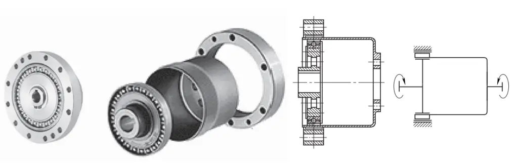
The harmonic drive reducer includes three basic components: wave generator, flexspline, and circular spline, as shown in Figure 18. Any one of the three components can be fixed, with the other two being active and passive, which can achieve reduction or acceleration, or be used as two inputs and one output, forming a differential transmission. Figure 19 shows a schematic structure of the harmonic drive reducer.
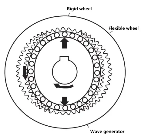
The working principle of the harmonic drive reducer is shown in Figure 20. When the circular spline is fixed, the wave generator is active, and the flexspline is passive, the flexspline deforms under the action of the elliptical wave generator, with the teeth of the flexspline at both ends of the wave generator’s major axis fully meshing with the teeth of the circular spline.
At both ends of the wave generator’s minor axis, the teeth of the flexspline completely disengage from the teeth of the circular spline; on the sides of the elliptical major axis, the teeth of the flexspline and the teeth of the circular spline are in a partially meshed state. On the side of the major axis rotation in the positive direction, it is called the meshing zone; on the side of the major axis rotation in the opposite direction, it is called the disengagement zone.
Due to the continuous rotation of the wave generator, the four states of meshing, full engagement, disengagement, and complete disengagement change in sequence, cycling continuously. Since the flexspline has a few less teeth (usually 2 or 4) than the circular spline, when the wave generator rotates one round, the flexspline turns a few teeth angle in the opposite direction, thus achieving a large reduction ratio.
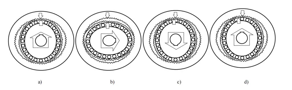
a)0°
b)90°
c)180°
d)360°
Compared with general gear transmission, harmonic drive has the following main features:
As many teeth are engaged in transmission at the same time, the transmission is smooth and the load capacity is high. Under the same working conditions, the volume can be reduced by 20%~50%.
If the meshing parameters are correctly selected, the relative sliding speed of the tooth surfaces is very low, resulting in minimal wear and high efficiency. When the structure is reasonable and the lubrication is good, for a transmission with i=100, the efficiency η can reach 0.85; for a transmission with i=75, the efficiency η can reach 0.92.
With the same manufacturing accuracy, the precision of harmonic drive can be one level higher than that of ordinary gear transmission. If the tooth surfaces are well ground, the transmission precision of harmonic gear drive can be four times higher than that of ordinary gear transmission.
The backlash of precision harmonic drive can generally be less than 3′~1′, and even backlash-free transmission can be achieved.
When using a long cup-type flexspline fixed transmission, motion can be transmitted into a sealed box, which is difficult to achieve with other transmission mechanisms.
Based on the above characteristics of harmonic reducers, they are widely used in robot joint transmission, often serving as the deceleration and transmission device for robot wrist joints.
The RV cycloidal pinwheel transmission device is composed of a single-stage planetary gear set followed by a single-stage cycloidal pinwheel reducer, as shown in Figure 21.
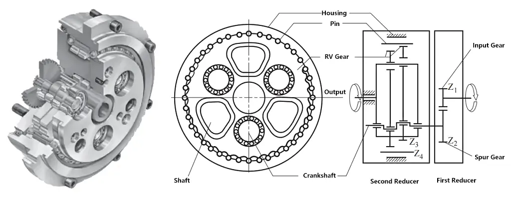
It has an input shaft, which drives 2~3 planetary gears distributed around the circumference through the gear on the shaft. Each planetary gear is connected to a bidirectional eccentric shaft, which in turn drives two radially opposed RV cycloidal gears to roll on the fixed shell with internal teeth. The cycloidal wheels then drive the disc output shaft to rotate through 2~3 non-cylindrical pin shafts distributed around the circumference.
Compared with harmonic drive, RV cycloidal pinwheel drive, besides having the same characteristics of high speed ratio, coaxial transmission, compact structure, and high efficiency, its most significant feature is good rigidity and small rotational inertia.
Compared with harmonic drive devices produced in Japan and used in robots, under the same conditions of output torque, speed, and reduction ratio, the volume of both is almost equal, but the latter’s transmission rigidity is 2~6 times greater. Converted to the input shaft, the rotational inertia is more than an order of magnitude smaller, but the weight has increased by 1~3 times.
The reason for the large overall weight and particularly small flywheel torque rotational inertia of the input shaft is that the RV transmission device adds a stage of planetary transmission, allowing the input shaft and gears to be made into a not very large cylinder, while the rotating parts behind, although very heavy, have their rotational inertia converted to the input shaft become very small after a stage of reduction.
Due to high rigidity, small rotational inertia, and relatively large weight, this reducer is particularly suitable for the first stage of rotation joint (waist joint) of robots, where the large self-weight is located on the base, and the high rigidity and small rotational inertia fully play their roles.
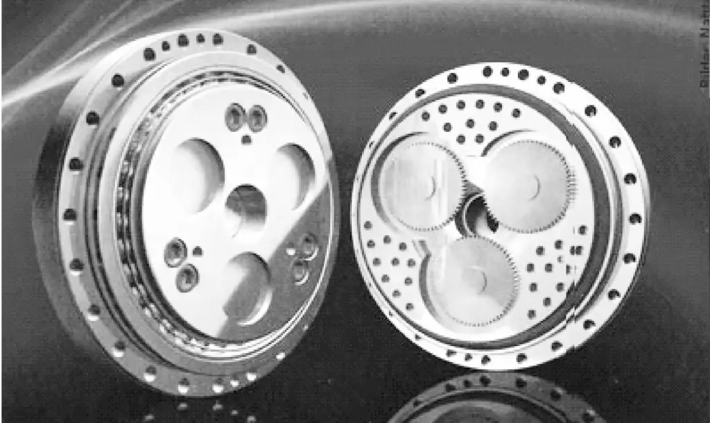
High rigidity can significantly increase the natural frequency of the whole machine, reducing vibration; small rotational inertia can improve response speed and reduce energy consumption during frequent acceleration and deceleration. Figure 22 shows a real image of the RV reducer.
Rolling helical transmission can achieve the conversion between rotary motion and linear motion. Its structure involves placing appropriate balls between the screw with helical grooves and the nut, changing the sliding friction between the screw and nut into rolling friction, a type of helical transmission, as shown in Figure 23. The screw 1 and nut 3 both have helical grooves with arc-shaped surfaces, and assembling them together forms a helical raceway, with ball 4 both rotating and rolling in it.
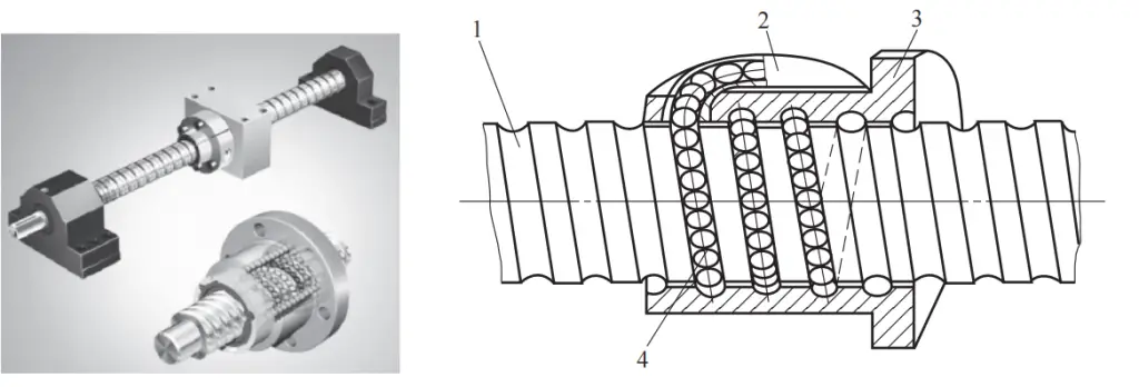
1—Screw
2—Raceway
3—Nut
4—Ball
The ball return channel has both internal and external circulation. The internal circulation structure is shown in Figure 24, where the balls in the internal circulation mode always remain in contact with the surface of the screw. In the adjacent two raceways, deflectors are installed. When the screw rotates, the balls start moving from the outlet of the deflector, move around for a cycle, then enter the deflector, forming a circulation loop.
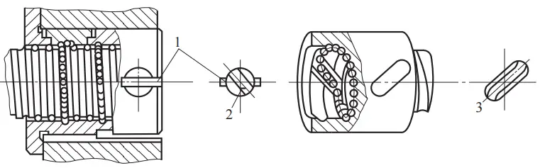
1—Key
2,3—Deflector Key
Generally, 2 to 4 reversers are installed on the same nut and are evenly distributed along the circumference of the nut. In the internal circulation structure, the ball circulation loop is short, smooth, efficient, and the radial size of the nut is also smaller, but the manufacturing precision requirements are high.
The structure of the ball external circulation is shown in Figure 25. For the helical groove type, when the screw rotates, the ball moves from the starting point, and when it reaches the endpoint, the ball blocker blocks the ball into the helical groove inside the nut support, and the helical groove leads to the starting point, forming a circulation loop.
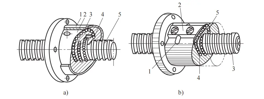
a) Helical groove type
1—Sleeve
2—Nut
3—Ball
4—Ball blocker
5—Screw
b) Tube insertion type
1—Bent tube
2—Pressure plate
3—Screw
4—Ball
5—Raceway
For the tube insertion type, when the screw rotates, the ball starts to move and can circulate through any raceway between two bent tubes, with the bent tube inside the nut support, not installing bent tubes in the already existing circulating raceway.
To eliminate backlash, the nut is divided into two sections, and the relative axial position of the two sections of the nut is adjusted with shims, double nuts, or tooth difference to eliminate the gap and apply preload, so that the backlash can be zero under the rated extraction load.
Figure 26 shows the adjustment of gap and preload, among which the double nut type is the most used, and the tooth difference type is the most reliable. Rolling helical transmission is most afraid of falling into dust, iron filings, sand grains. Usually, both ends of the nut must be sealed, and the exposed part of the screw must be sealed with a “bellows” cover or a steel band wrap.
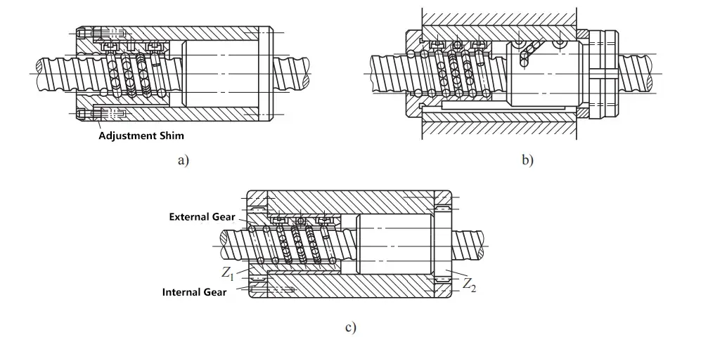
a) Shim type
b) Double nut type
c) Tooth difference type
The working condition of the rolling helical pair is similar to that of rolling bearings, so its load capacity is also expressed in terms of rated dynamic load and rated static load, with the definition, calculation, and selection method being basically the same as that of rolling bearings.
The size specifications of the rolling helical pair are generally determined by the rated dynamic load or rated static load. For slender rolling screws that bear compressive loads, a check for the stability of the compression rod is required; for rolling screws with high speed and large support distance, a calculation of the critical speed is required.