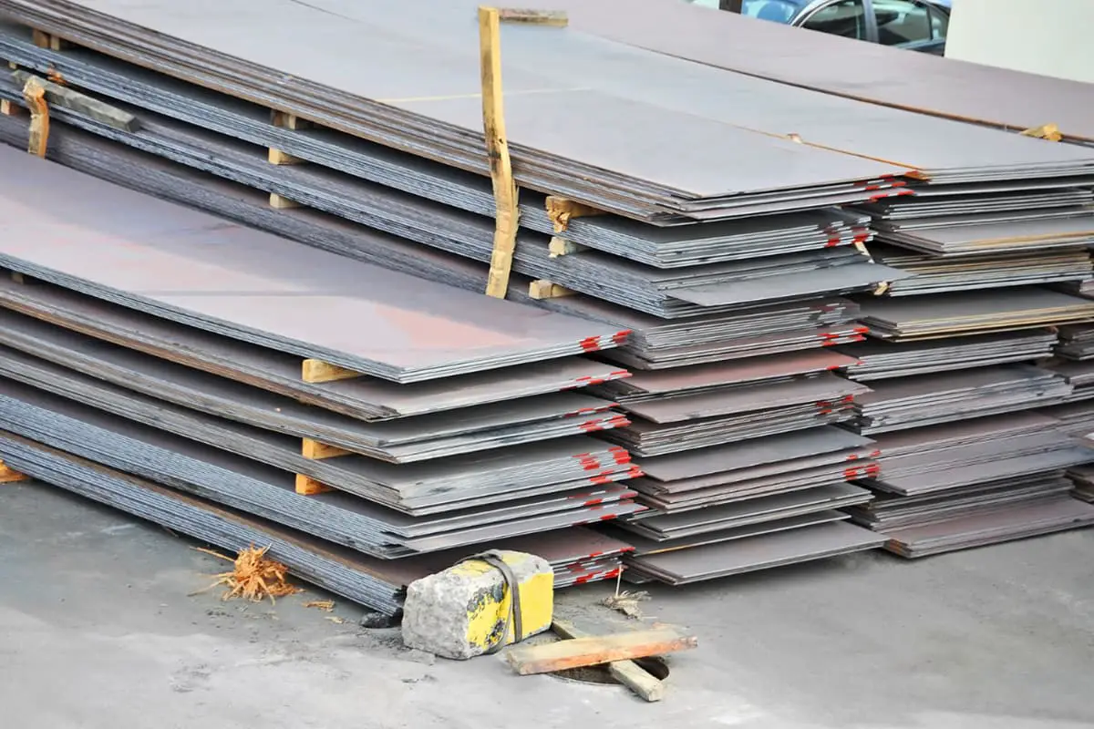
Materials and raw parts may exhibit defects, such as bulging, bending, twisting, and wave-like distortions. Before cutting, slicing, and forming, it is essential to level the materials.
Leveling Process
Causes of Material Deformation and Corrective Principles
(1) Causes of Material Deformation
Material deformation can result from the residual stress of rolling, from the processing of the material, and from improper lifting, transportation, or storage.
(2) Leveling Principles
By applying external forces or heat (thermal expansion and contraction), the shorter fibers in the material can be elongated, or the longer ones can be shortened, ultimately making the lengths of all fiber layers approximately equal.
Types of Leveling Methods
Leveling methods are categorized into cold leveling and hot leveling, depending on whether heat is applied. They are also divided into manual leveling, mechanical leveling, and flame leveling based on the source and nature of the applied force.
Leveling Techniques
Common leveling methods include manual and mechanical leveling. Mechanical leveling encompasses machine leveling, friction press leveling, profile straightening machine leveling, and vibratory hammer forming machine correction.
(1) Manual Leveling
Manual leveling involves using hammers or twisting methods to correct the deformation of parts. It is a flexible and straightforward method mainly used for parts that equipment cannot level. Tools commonly used in manual leveling include hammers, sledgehammers, mallets, dead blow hammers, jacks, vise grips, etc., with the primary fixture being a platform.
Measuring tools primarily include straightedges, feeler gauges, and templates. Manual leveling scope: straightening of shearing and cutting lateral bends, small angle steel straightening, manual leveling of forming defects in workpieces.
(2) Machine Leveling
Machine leveling is primarily used for carbon steel plates, stainless steel plates, and aluminum alloy plates, divided into thin plate leveling and thick plate leveling.
(3) Types of Plate Bending and Leveling Principles
Plate bending is divided into planar (two-dimensional) bending and spatial (three-dimensional) bending, as shown in Figure 3-159. The principle of plate leveling is to cause plastic deformation of the metal plate under the action of the leveling roller, achieving a flat state, as shown in Figure 3-160.
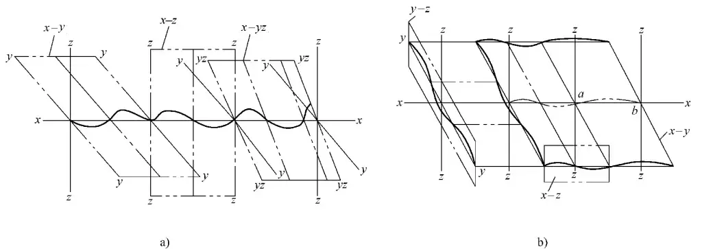
a) Two-dimensional Bending Diagram
b) Three-dimensional Bending Diagram

Leveling Machines and Their Applications
Thin and Thick Plate Leveling Machines
For the leveling of stamping parts of rail passenger cars, two types of equipment are used according to the thickness of the workpiece: thin plate leveling machines and thick plate leveling machines.
The appearance of the thin plate leveling machine is shown in Figure 3-16a, and its technical parameters are given in Table 3-108. This machine uses 19-roller precision correction, leveling plates of thickness 0.5~8mm, with the adjustment accuracy of the straightening rollers at ±0.01mm.
Table 3-108 Technical Parameters of the 19-Roller Precision Thin Plate Leveling Machine
| Material | Steel, Stainless Steel, Aluminum Alloy |
| Surface Characteristics | Not a surface-sensitive material, not a material prone to oxidation and rust |
| Geometric Tolerance | Thickness shape tolerance conforms to EN standards |
| Tensile Strength | Refer to the Leveling Performance Chart |
| Yield Strength | Refer to the Leveling Performance Chart |
| Material Cross Section | Refer to the Straightening Performance Chart |
| Minimum Material Length (through direction) | 100mm |
| Material Width | 1650mm |
| Pass-through Speed | 3~12m/min |
| Leveling Roller Diameter | 56mm |
| Number of Leveling Rollers | 19 |
| Adjustment Accuracy of Leveling Rollers | ±0.01mm |
| Pass-through Height Above Ground | 950mm |
| Required Space (Length × Width × Height) | 3900mm×2350mm×2050mm |
The appearance of the thick plate leveling machine is shown in Figure 3-16b, and its technical parameters are given in Table 3-109. This machine uses 13-roller precision correction, leveling plates of thickness 6~22mm, with the leveling flatness of 0.5mm/m2.
Table 3-109: Technical Specifications of the 13-Roll CNC Thick Plate Leveling Machine
| Material | Units | Notes |
| Type of Material | Ordinary Carbon Steel, High-Temperature Resistant Steel, High-Alloy Steel, Stainless Steel, Aluminum Alloy | |
| Material Condition | Punching, Shearing, Flame Cutting, Plasma Cutting, Laser Cutting, Surface Shot Blasting, etc. | |
| Maximum Yield Strength | N/mm2 | 700: Thickness 22mm, Full Length 900mm: Thickness 20mm, Full Length 1000mm |
| Minimum Leveling Thickness | mm | 6 |
| Maximum Leveling Thickness | mm | 22 |
| Leveler Related Parameters | ||
| Maximum Leveling Width | mm | 1650 |
| Number of Leveling Rolls | n° | 13 |
| Diameter of Leveling Rolls | mm | 180 |
| Number of Upper Support Rolls | n° | 4 Rows of 8 Rolls, Total 32 Support Rolls |
| Number of Lower Support Rolls | n° | 4 Rows of 9 Rolls, Total 36 Support Rolls |
| Diameter of Support Rolls | mm | 200 |
| Load-bearing Capacity of Each Support Roll | kN | 1000 |
| Adjustable Leveling Speed | m/ min | 0 ~ 15 |
| Main Motor Power (Approximate) | kW | 175 (Speed 1200r/min) |
| Flatness Accuracy | 0.5mm/m² | |
| Machine Weight (Including Motor) | kg | 65000 |
| Machine Dimensions (L×W×H) | mm | 2500 x 4200 x 3650 |
| Working Table Height | mm | 800 |
Adjustment Values for the Inlet and Outlet Sides of the Leveling Machine
Depending on the thickness of the material, select the values for the inlet and outlet sides of the leveling machine. For different materials and different shapes of parts, the values for the inlet and outlet sides will vary; the parts with high yield strength and large cross-sections have larger inlet adjustment values.
Table 3-110 shows the adjustment values for the inlet and outlet sides of the thin plate leveler; Table 3-111 shows the adjustment values for the inlet and outlet sides of the thick plate leveler.
Table 3-110: Adjustment Values for Inlet and Outlet Sides of Thin Sheet Leveling (Unit: mm)
| Sheet Thickness | Inlet Side Limit Adjustment Values | Inlet Side Adjustment Values | Outlet Side Adjustment Values |
| 0.5 | -2.4 | -1.2 | 0.5 |
| 0.8 | -2 | -0.8 | 0.8 |
| 1 | -1.2 | -0.6 | 1 |
| 1.5 | -0.9 | 0.1 | 1.5 |
| 2 | -0.4 | 0.6 | 2 |
| 2.5 | 0.1 | 1 | 2.5 |
| 3 | 0.8 | 1.7 | 3 |
| 4 | 1.9 | 2.8 | 4 |
| 4.5 | 2.5 | 3.4 | 4.5 |
| 5 | 3.2 | 3.8 | 5 |
| 6 | 4.3 | 5 | 6 |
| 8 | 6.6 | 7.2 | 8 |
| 10 | 8.8 | 9.2 | 10 |
| 12 | 10.8 | 11.2 | 12 |
Table 3-111: Adjustment Values for Inlet and Outlet Sides of Thick Sheet Leveling (Unit: mm)
| Material Thickness | 4° | 3° | 2° | 1° |
| 6 | 5. 87 | 5.91 | 4.01 | 3.98 |
| 8 | 7.71 | 7.71 | 5.83 | 5.83 |
| 10 | 9.88 | 9.89 | 7.61 | 7.58 |
| 12 | 11.79 | 11.76 | 9.6 | 9.57 |
| 14 | 13.75 | 13.69 | 11.56 | 11.50 |
| 16 | 15.85 | 15.87 | 13.68 | 13.63 |
| 18 | 17.88 | 17.87 | 15.66 | 15.62 |
| 20 | 19.86 | 19.86 | 17.61 | 17.57 |
| 22 | 21.85 | 21.85 | 19.57 | 19.52 |
Leveling Direction
Figure 3-161 illustrates the leveling direction of the part.

Leveling Process
1) Select the adjustment values for the inlet and outlet sides based on the material, thickness, and shape of the part to be leveled.
2) Trial leveling of the first piece.
3) Correct the adjustment values for the inlet and outlet sides based on the leveling inspection results of the first piece.
4) Repeat trial leveling, inspection, and correction several times to determine the final values for the inlet and outlet sides.
5) Proceed with batch leveling production.
Inspection
Perform 100% flatness inspection of the leveled parts. Any non-conforming parts exceeding the standard are subjected to secondary or multiple leveling treatments until the flatness of the part meets the requirements.
Straightening Hydraulic Press Leveling
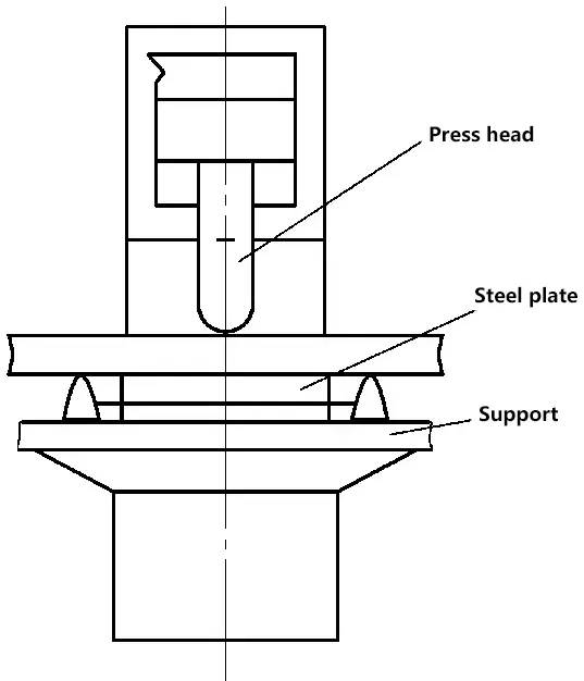
For workpieces that exceed the leveling capacity of the roller leveling machine, a pressure correction method is used. Figure 3-162 shows a schematic diagram of using a straightening hydraulic press to level thick plates.
Friction Press Leveling
For small-sized sheet metal and profile parts, deformations also occur during the stamping process. However, due to the small size of these parts, they cannot be leveled with a leveling machine. Instead, a friction press is used to forcibly level them.
Figure 3-163 shows several common methods of correction using a friction press, such as overlapping leveling of multi-layer deformed parts, thick plate leveling, and leveling with a process cushion iron.
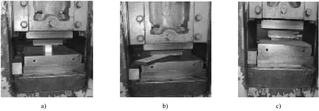
a) Overlapping thin plates for leveling
b) Thick plate leveling
c) Applying a process cushion iron in the middle
Section Steel Straightening Machine Leveling
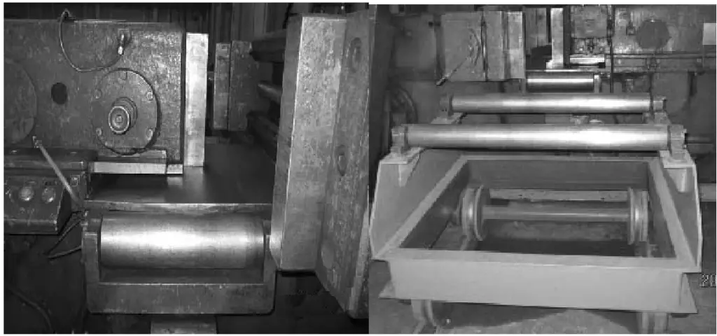
The angle steel, channel steel, and other profiles used in bus production can become deformed during transportation and cutting. These deformations are corrected using a section steel straightening machine (for straightening). The section steel straightening machine, as shown in Figure 3-164, has a horizontal structure and is hydraulically driven.

1 – Hydraulic Cylinder,
2 – Press Head
3 – Support Crossbeam
4 – Movable Pivot
5 – Hydraulic Control Board
6 – Electric Motor
7 – Oil Tank
8 – Oil Pump
9 – Foot Pedal Switch
The section steel straightening machine uses a reverse bending method for straightening. The profile is placed between the press head and the fulcrums. The distance between the two fulcrums can be adjusted according to the length and degree of bending of the profile.
The force exerted by the press head acts on the profile to be leveled, causing it to bend in the opposite direction. Depending on the degree of bending of the profile, it is leveled in stages until it is completely straightened. Figure 3-165 shows the section steel support device.
In addition to straightening section steel, the section steel straightening machine can also level some special structure thick plates and reshape formed parts. Figure 3-166 shows the straightening of angle steel and the leveling of special components, respectively.


