Key Parts of Mechanical Press Machines Explained
Ever wondered what makes a mechanical press machine tick? From the flywheel to the clutch and brake, each part plays…
Are you using your mechanical press to its full potential? Ensuring proper usage and maintenance of this essential equipment is crucial for quality production, efficiency, and safety. This guide will walk you through key steps and best practices for operating and caring for your mechanical press, helping you avoid common pitfalls and extend the machine’s lifespan. Discover practical tips to keep your press in top condition and your operations running smoothly.
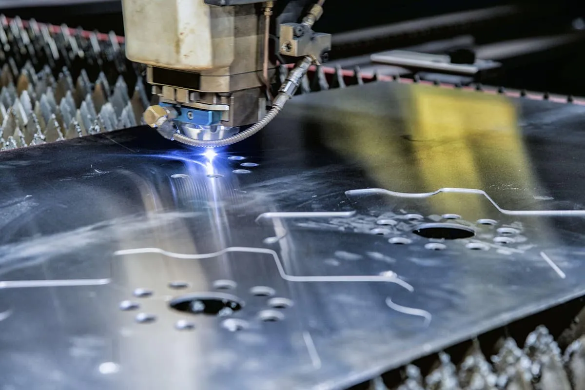
The press is one of the basic equipment for stamping production. Whether it is used and operated correctly is directly related to product quality, production efficiency, the technical condition of the press, the service life of the mold, production costs, and a series of important issues such as personal and equipment safety.
To use the press properly, the following tasks should be performed at different times.
(1) Be familiar with the stamping process procedures, prepare for production according to the stamping process card, and guide production.
(2) Remember the safety production norms, regulations, and rules for stamping.
(3) Understand the structure, performance, and technical parameters of the online press.
(4) Before stamping operations, organize the environment around the press, and lubricate at fixed points, with fixed quality, at fixed times, and in fixed quantities.
(5) Clarify the functions and operation adjustment methods of various switches, buttons, indicator lights, and meters.
(6) Before starting, check for any abnormal conditions in the press, such as whether the positions of various knobs are correct, and whether the position of the feeding device is correct. The clutch must be in a non-working state before the motor is started.
(7) The slider can only be started after the motor flywheel reaches the rated speed.
(8) If the motor does not rotate when the start button is pressed, immediately press the stop button to prevent the motor from burning out.
(9) The installation and adjustment of the die should be carried out by a dedicated adjuster, stamping technician, or a qualified senior stamping worker. Small and simple structure dies can be adjusted under the guidance of the above-mentioned adjusters and qualified personnel. The closing height of the press must be greater than the closing height of the die.
Also, measure the closing height when the slider is at the bottom dead center. When adjusting the die on a press without a fine-tuning device, control the number of operations to prevent the clutch and brake from overheating. Use a torque wrench for die installation and adjustment.
(10) Before starting stamping operations, run the press empty for 5-10 minutes to check for any abnormal sounds. Start production only after confirming normal conditions.
(11) The installed and debugged die can only be handed over to the stamping worker for production after the trial-stamped parts pass inspection. Stamping workers must be trained before taking up the post and operate the stamping machine with qualified certification.
(12) Stamping workers should operate fixed machines at fixed positions, so they can familiarize themselves with the structure and master the operation techniques. This also facilitates cleaning and maintenance according to the structural characteristics and tonnage of the press. They should purchase and make complete sets of handheld tools as needed, such as hooks for removing workpieces from the die, feeding tongs, and cleaning scrapers.
(13) During stamping, materials, dies, and equipment all need lubrication. Stamping workers should know in advance that different lubrication objects require different lubricants and lubrication methods. They should understand the lubrication methods, tools, and containers in advance. Some lubricants need to be prepared by themselves, so they must know the lubricant formula and preparation method.
(14) During stamping, workers should conduct self-inspection of the stamped parts, so they should be equipped with basic measuring tools: steel rulers, vernier calipers, feeler gauges, etc., and know how to use them.
(15) Wear personal noise protection devices, such as earplugs and noise-canceling hats.
(1) Fully understand the technical requirements of the stamped parts and the quality indices given in the drawings. Master the key points of processing the stamped parts. Check whether all equipment, dies, and materials meet the requirements according to the stamping process card and ensure the production of qualified stamped parts.
(2) If strip material is used, manually feed the material after cleaning the surface, measure the strip dimensions, and ensure no positive deviation in the width of the strip material. Remove burrs from sheared strips in advance. The strip surface should be free of rust, dirt, and unevenness. If conditions permit, level the strip before stamping.
(3) The operator must not leave the workstation, must stay focused, and constantly monitor the press operation. If a malfunction is detected, stop the machine immediately and start troubleshooting.
(4) The material must not be fed crookedly or overlapped, and there should be no debris, rust, or scrap between the upper and lower dies.
(5) Special care must be taken to protect the working surface, sliding surface, and protective devices of the press, such as ladders, railings, and guards. Protective devices must not be moved or removed arbitrarily.
(6) Check whether the oil supply at each lubrication point is adequate and whether the vernier or oil level indicator is within the specified range. If abnormal sounds, smells, or gauge readings (such as oil pressure, air pressure, current, etc.) are detected, stop the machine immediately and have a maintenance worker inspect and repair it.
(7) When reverse operation is needed, wait until the motor has completely stopped before reversing. Do not reverse while the flywheel is rotating.
(8) Regularly check whether the bolts fastening the die are loose, and tighten them with a torque wrench.
(9) All buttons and switches must be operated correctly. Do not press switches with wooden sticks or iron blocks, and do not kick manual buttons with your feet.
(10) After replacing the friction block (piece) of the clutch, control and reduce the number of single strokes.
(11) If the slide stops and the downward distance is too large (braking angle is large), have a maintenance worker adjust the brake to prevent personal and equipment accidents.
(12) During production, the stamping worker must self-inspect the stamped parts without stopping the machine and observe the operation of the press. If any abnormality is found, stop the machine immediately.
(1) Check for any scratches on the sliding surface of the press.
(2) Keep the press tidy and clean regularly.
(3) Check the technical condition of the die and any existing problems to determine if sharpening or repair is needed. If the technical condition of the die is poor, record the problems in the plan and repair sheet, and fill out the die life card.
(4) If the technical condition of the die is good and no sharpening or repair is needed, clean it, apply anti-rust oil, attach the last stamped sample, and fill out the stamping record and die life card before sending it to the mold library.
(5) Take the last stamped workpiece, attach the stamping part drawing, stamping process card, and production plan task sheet, and send it to the inspector. Wait for the inspection report to confirm that the stamped workpiece is qualified, check the technical condition of the die and any existing problems, and draw a conclusion before removing the die.
(6) Sort and send the stamping scrap frame and punching waste to the scrap library according to the categories and grades of steel and non-ferrous metals.
(7) For stamped parts that need to be processed in the next sequence, transfer them according to the production dispatcher’s instructions or the process route shown on the process card, or send them to the semi-finished product library.
Mechanical presses in poor technical condition should be stopped for inspection to promptly detect and quickly eliminate problems, avoiding small faults from developing into major equipment accidents, causing greater losses and affecting production.
There are many types of presses with different structures, and the faults that occur during production are also varied. Here, only some common fault phenomena, causes, and troubleshooting methods of typical structural components are provided. Common faults of the key clutch are shown in Table 1. Common faults of the friction clutch are shown in Table 2. Common faults of the slider mechanism are shown in Table 3. Common faults of the drawing pad are shown in Table 4.
Table 1 Common faults of the key clutch
| Serial number | Fault phenomenon | Fault cause | Troubleshooting method |
| 1 | Single stroke clutch does not engage | The edge of the key plate is rounded and slips | Repair (weld) or replace with a new one |
| Insufficient force of spring 3 | Adjust or replace | ||
| Rotation key spring broken | Replace with a new spring | ||
| Rotation key tail broken | Replace with a new rotation key | ||
| 2 | Slider vibrates and pauses at the bottom dead center | Brake band broken | Replace with a new one |
| Spring of rotation key 5 broken | Replace with a new one | ||
| 3 | Sharp continuous noise when clutch disengages | Brake band too tight | Adjust to normal |
| Rotation key spring loose | Adjust to normal | ||
| 4 | Rhythmic noise from clutch when flywheel is idling | Rotation key not fully seated in the groove | Remove and repair |
| Curved surface of rotation key higher than the shaft surface | Remove and repair | ||
| 5 | Heavy noise when clutch disengages | Brake too loose | Adjust to normal |
| 6 | Continuous operation during single stroke | Spring 7 too loose or broken | Adjust to normal or replace the spring |
| Spring 5 too tight or broken | Adjust to normal or replace the spring | ||
| 7 | Severe impact on the stop key | Burrs on rotation key 4 | Remove and repair or replace |
| Crankshaft groove has burrs | Remove and repair or replace | ||
| Coupling steel sleeve has burrs | Remove and repair or replace |
Table 2 Common faults of friction clutches
| Serial number | Fault phenomenon | Cause of fault | Troubleshooting method |
| 1 | Clutch does not engage tightly, slider does not move or moves very slowly | Gap is too large | Adjust the gap or replace the friction plate |
| Air valve malfunction | Repair the air valve | ||
| Seal is leaking | Replace the seal | ||
| Friction surface has oil | Clean it | ||
| Guide pin or guide key is worn | Disassemble and repair or replace with new parts | ||
| 2 | Slider slips and cannot stop the car | Brake friction surface gap is large | Adjust or replace |
| Air valve malfunction | Repair the air valve | ||
| Spring is broken | Replace the spring | ||
| Balance cylinder has no air or air pressure is low | Supply air or eliminate air leakage | ||
| Guide pin or guide key wear | Remove for repair or replace with new parts | ||
| 3 | Friction block wears too quickly or temperature rises abnormally | Pneumatic interlock is abnormal, clutch and brake interfere with each other | Adjust the time difference between the two air valves |
| Inconsistent thickness of friction blocks | Replace the friction blocks again | ||
| Foreign objects between friction surfaces | Remove foreign objects | ||
| Friction disc misalignment | Reinstall and adjust | ||
| 4 | Excessive slide distance of the slider during braking | Large gap between friction plates in the braking part | Adjust the gap |
| Incorrect cam position, exhaust not timely during braking | Adjust the cam position |
Table 3 Common faults of the slider mechanism
| Serial number | Fault phenomenon | Cause of fault | Troubleshooting method |
| 1 | Slider cannot be adjusted when adjusting the closing height | Adjusting screw bent | Replace or straighten |
| Adjusting screw thread and connecting rod stuck | Replace or repair the thread | ||
| Worm gear (or together with the adjusting nut) bottom or side or tooth bulging part stuck with the slider body (or shell) | Lightly repair and scrape the car pin, heavily replace with new parts | ||
| Adjusting screw ball head gap too small, ball head and ball seat stuck | Enlarge the gap, clean the ball seat, remove scars | ||
| The ball head is slightly loose and stuck on the slider | Reassign the pin | ||
| The pressure of the balance cylinder is too high or too low | Adjust the pressure | ||
| The rolling bearing of the worm shaft is broken | Replace the bearing | ||
| The gap between the guide rails is too small | Adjust the gap | ||
| Motor or electrical fault | Electrician maintenance | ||
| The lock is not released | Release | ||
| 2 | The link slider of the ball head structure automatically changes the closing height during operation | This phenomenon occurs in the link slider mechanism without a locking mechanism because the worm gear does not ensure self-locking | Reduce the helix angle, etc. On a double-link press, a brake can be used as a temporary measure |
| In the link slider mechanism with a locking mechanism, it is often because the closing height is adjusted and then forgotten to lock or not locked enough | Readjust the lock | ||
| 3 | The slider is stuck at the bottom dead center | Overload (improper adjustment of closing height, double feeding) | If there is no other reason after checking the transmission system, disengage the clutch, start the motor in reverse, and when it reaches the rotational speed, turn off the motor. Use the flywheel inertia, manually operate the air valve to engage the clutch, and withdraw the slider from the jam. If it doesn’t work once, repeat several times |
| 4 | When adjusting the closing height, the slider rises or falls endlessly | Limit switch failure | Repair the limit switch, but be sure to pay attention to the position of the upper and lower limit travel switches when adjusting the closing height, do not arbitrarily remove them, otherwise a major accident may occur |
| 5 | The ejector screw and stopper are bent or broken | The ejector screw was not adjusted accordingly when adjusting the closing height | Replace damaged parts |
| When adjusting the closing height, first adjust the ejector screw to the maximum distance, and after the closing height is adjusted, reduce the ejector distance as required | |||
| 6 | The slider of the double-link or four-link press has a swinging phenomenon during operation | This situation occurs in presses where the two links swing in the same plane due to the inconsistency of the positions of the gears and the eccentric wheel or crankshaft key | Adjust using the offset key method |
Table 4 Common Failures of Deep Drawing Pads
| Serial Number | Failure Phenomenon | Cause of Failure | Troubleshooting Method | ||
| 1 | Deep drawing pad plunger does not rise or does not reach the top | Sealing ring is too tight | Loosen the tightening screw or replace the sealing ring | ||
| Uneven force on the sealing ring | Adjust evenly | ||||
| Support plate is stuck | Guide rail is too tight | Make relevant adjustments | Enlarge the guide rail gap | ||
| Scrap or ejector rod is stuck between the support plate and the workbench plate | Remove the scrap, plug the unused holes on the workbench with plugs | ||||
| Support plate is deflected and stuck by the press bed | Adjust the support plate and tighten the screws | ||||
| Insufficient air pressure | Adjust the air pressure and eliminate air leaks | ||||
| Piston of the pressure cylinder blocks the oil inlet | Remove the air from this cylinder | ||||
| 2 | Deep drawing pad plunger does not descend | Uneven or too tight sealing ring pressure | Adjust the sealing pressure | ||
| Air in the deep drawing pad cylinder cannot be expelled | Exhaust the air | ||||
| Support plate guide rail is too tight | Adjust the gap | ||||
| Wear on the moving surface | Repair | ||||
| 3 | The hydraulic air cushion does not get the required clamping pressure | Not enough oil | Refuel | ||
| The piston in the clamping pressure cylinder is stuck or the cylinder does not intake air, so the piston does not move | Clean the cylinder, check the air pipeline and air valve | ||||
| The piston head of the clamping pressure cylinder is not sealed tightly, causing oil leakage at the hydraulic air cushion inlet | Disassemble, grind, and repair | ||||
| 4 | The plunger of the hydraulic air cushion rises unsteadily, even with impact | Poor lubrication between the cylinder wall and piston, high friction, or the hydraulic air cushion oil is contaminated with too much condensate water | Clean and remove rust, enhance lubrication, replace the oil, and strengthen daily inspection and water drainage | ||
| Uneven clamping force of the sealing ring | Adjust the clamping force | ||||
| 5 | After generating clamping pressure, the hydraulic air cushion does not produce qualified parts | Incorrect cam position, clamping pressure is not generated in time | Adjust the cam position | ||
| The support plate of the hydraulic air cushion is not parallel to the die pressure ring, causing uneven clamping force | Adjust the parallelism of the support plate and the pressure ring | ||||
New mechanical presses from the factory are strictly inspected according to national standards and higher enterprise standards. To maintain the factory condition of the press for stamping and extend its lifespan, proper maintenance is required after the new machine is put into production.
Under normal circumstances, Chinese-made mechanical presses are used online for about 10 years before the first major overhaul. After the overhaul, the press loses its factory technical condition and precision. If the press is to continue in service, it can only be used at a downgraded level. Routine primary maintenance of the press is generally carried out by stamping workers in collaboration with professional maintenance electricians and machinists, with the main items listed in Tables 5 and 6.
Table 5 Primary maintenance of open presses
| Serial number | Maintenance part | Maintenance content and requirements |
| 1 | External maintenance | Wipe the exterior and cover of the press, keep it clean inside and out, free of rust and “yellow robe” |
| Replenish screws, nuts, and handles, and tighten them with a torque wrench | ||
| 2 | Transmission part | Check and adjust the tension of the drive belt |
| Check that the clutch is in good working condition | ||
| Check the gap between the slider and the guide rail | ||
| 3 | Lubrication part | Check and adjust each lubrication point to ensure good oil supply |
| Check the oil quality to ensure it is good | ||
| 4 | Electrical part | Lightly wipe the motor and electrical appliances |
| Check and adjust to ensure that various operations are correct and reliable | ||
| Electrical devices should be safe, fixed, and tidy | ||
| Check and adjust the safety limit device to ensure safety and reliability | ||
| 5 | Safety protection device | Check if it is sensitive and reliable |
Table 6 Primary maintenance of closed press
| Serial number | Maintenance part | Maintenance content and requirements |
| 1 | External maintenance | Wipe the surface and cover of the press to keep it clean inside and out, free of rust and “yellow robe” |
| Clean the oil and debris from the T-slots and mounting screw holes | ||
| Replenish external screws | ||
| 2 | Transmission part | Check for abnormal sounds in the transmission part |
| Check if the brake angle is appropriate | ||
| Check for oil leakage in each part and eliminate it as much as possible | ||
| Check if various indicator lights are normal and take measures to handle them | ||
| 3 | Slider part | Check for air leaks in the balancing device and eliminate them as much as possible |
| The quick clamping mechanism of the die should work reliably | ||
| Check and adjust the pneumatic ejector mechanism to ensure reliable and normal operation | ||
| Check and adjust the overload device to ensure sensitivity and reliability | ||
| 4 | Drawing pad part | Check if the pressing force and release force are normal |
| Check if there are any indentations on the trimming drawing support plate | ||
| Clean up waste materials from all parts of the drawing pad | ||
| Adjust the stroke adjustment mechanism of the drawing pad to ensure flexibility and reliability | ||
| 5 | Oil and gas system | Eliminate oil and gas leaks |
| Check if various pressure gauges are sensitive and reliable | ||
| Check the oil levels in each oil tank and replenish if insufficient | ||
| Adjust each lubrication point to ensure good oil supply | ||
| 6 | Safety and protective devices | Check if they are complete, sensitive, and reliable |
| 7 | Electrical part | Lightly wipe the motor and electrical appliances |
| Check, adjust, and ensure that various operating specifications are correct and reliable | ||
| Electrical devices should be safe, fixed, and tidy | ||
| Check and adjust the safety limit devices to ensure safety and reliability |
Closed presses, especially multi-point closed presses, are large and medium-sized modern stamping equipment on the outer covering stamping production lines in the automotive industry (mainly car manufacturing). They have complex structures, complete functions, and a high degree of automation.
Among them, the multi-link closed four-point mechanical press not only has a multi-link transmission system but also is equipped with a hydraulic unloading safety device with pre-selected tonnage. The workbench is a semi-automatic mold change trolley, and the upper and lower molds use electric or hydraulic clamping devices. The lubrication system uses a PLC-controlled quantitative oil supply system, and the drawing pad system uses a pure air type.
This type of high-tonnage, advanced design press has a stamping frequency of 3.2 times/min on the production line. With three shifts and continuous production without stopping, it works 22.5 hours a day, with 4320 stampings per day, and an average downtime rate of less than 5%. After 5 million stampings, and up to a maximum of 12 million stampings, various faults begin to appear in this type of press, necessitating necessary repairs. See Table 7 for details.
Table 7 Common Faults and Troubleshooting Methods for Multi-Link Closed Four-Point Presses
| Serial Number | Fault Name | Fault Location and Consequences | Causes of Faults and Accidents | Troubleshooting Methods |
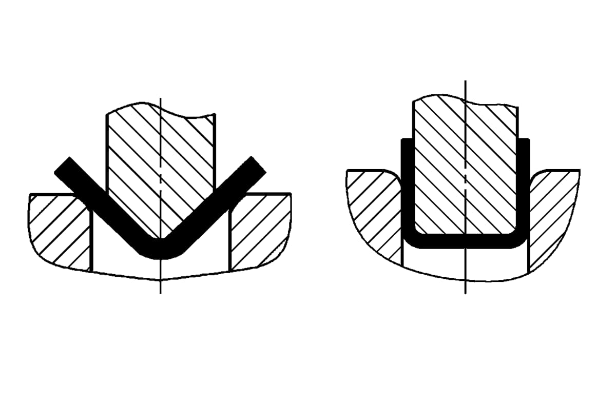
| 1 | Head Fracture of Hexagon Socket Head Cap Screw | Flywheel support sleeve end face screw M36×100, pre-tightening torque 895N·m, 3 pieces fractured, causing severe flywheel wobble, extremely dangerous | Screws and nuts, as standard fasteners, are produced by specialized factories. Due to poor manufacturing quality of the screws, small root fillets, too deep hexagon sockets, and insufficient strength, fractures occur. | Remove the flywheel, replace the screws, and use a torque wrench |
| Clutch end cover tightening screw M30×220, 9 pieces, pre-tightening torque 885N·m, 4 pieces fractured, causing clutch noise and impact, making it inoperable | Remove the clutch, replace the screws, and use a torque wrench | |||
| Brake end cover tightening screw M24×180, 12 pieces, pre-tightening torque 470N·m, causing impact, requiring shutdown for repair | Remove the brake, replace the screws, and use a torque wrench | |||
| 2 | Hexagon Head Screw Loosening or Fracture | Lower air cushion installation screw M48×200, 8 pieces, nuts loosened, causing complete fall, uneven force on screws leading to fracture, ultimately causing air cushion tilt and shutdown | These large screws should be pre-tightened and glued to prevent loosening during installation. Loosening often occurs due to installation negligence and failure to follow assembly procedures. | Lift the tilted air cushion, replace the screws and nuts, pre-tighten with heating, and apply glue to prevent loosening |
| Multi-link system pin end face key tightening screw fracture or loosening inside the beam, M12×60, M16×60, 8 pieces each, causing axial displacement of the multi-link and mechanism vibration | Caused by axial impact load on the multi-link pin of unknown origin, leading to strength failure, and small root fillets on the screw head causing stress concentration | Replace the screws and use a torque wrench | ||
| 3 | Hexagon Head Screw Nut Loosening | Main motor base lifting pin uses double nuts for anti-loosening. Under vibration, both nuts loosen, causing the 1.5m long pin to axially slip out of the pin hole, leading to sudden motor drop, nearly causing a major accident | The reason is that double nut anti-loosening is unreliable | Reinstall the pin, apply glue to prevent loosening |
| Main drive camshaft bearing seat cover screw of double-action press loosens, causing the cover to jump, breaking the cover positioning stop, leading to severe camshaft jump and loss of machine accuracy | The reason is that the double nut anti-loosening is unreliable | Remove the main drive camshaft, reassemble the screws, and apply glue to prevent loosening | ||
| 4 | Bearing stickiness | The clutch rotary joint bearing is not flexible, causing the clutch rotary joint to rotate with the flywheel, twisting off the hose, breaking the shell cover, and almost injuring people | The reason is the poor quality of the bearing | Reliable high-quality bearings should be used or bearings should be replaced regularly |
| 5 | Seal aging and oil leakage | The large seals used for the brake and flywheel bearings cause lubricating oil to be thrown off along the flywheel, affecting operation and polluting the transmission belt | Every machine has this fault. Chinese-made polyurethane material is hard and easy to age, completely turning into a broken honeycomb coal shape after 3 years | Regularly replace the seals, switch to nitrile material which has a much longer lifespan |
| 6 | Seal leakage | The seal of the hydraulic cylinder that lifts the mold changing trolley leaks oil, preventing the hydraulic cylinder from building up oil pressure, and the trolley cannot be opened inside the machine tool | All mold changing trolleys have this fault, the reason being seal aging | Replace domestic seals with imported ones |
| 7 | External hexagon screws loosen | The fastening screws M48×300 of the eccentric wheel assembly of the main drive system, 4 pieces, loosened. The original design used positioning welding to prevent loosening after pre-tightening the nuts. The impact load caused the welding positioning to crack, the large nuts loosened, and the screw rod moved axially. If not detected in time, it would cause serious component damage | The reason is that the method of using positioning welding to prevent loosening of the nuts is unreliable, and the welding points crack | Due to the narrow installation space, pre-tightening is not possible, so only slightly tighten the nuts and apply glue to prevent loosening |
| In the cam switch transmission system inside the beam, the screws M16×20 of the first-stage transmission gear seat loosen, causing the transmission gear to move axially, destroying the synchronization between the cam switch and the main drive, resulting in confusion in the slider’s working regime | The reason is that the screws have no anti-loosening measures | Tighten the screws and apply glue to prevent loosening | ||
| The round nut anti-loosening pad of the first-stage gear shaft radial thrust bearing block is damaged, causing the inner ring of the bearing to move axially, losing bearing precision, and causing severe clutch shaft vibration | The reason is that the tongue of the anti-loosening washer broke, causing anti-loosening failure | Remove the clutch, flywheel, and support sleeve, replace the anti-loosening washer, apply anti-loosening glue, and tighten the screws | ||
| 8 | External hexagon set screws loosen | The set screws of the connector guide post cross pin loosen, causing the cross pin to move axially, cutting the guide sleeve, deforming the guide post, and causing a shutdown | The reason is that the anti-loosening steel wire broke, making the set screws unreliable for anti-loosening | Traditional anti-loosening methods are completely ineffective, change the structure |
| 9 | Saddle tile excessive wear | The saddle tile bearing the load of the connector is excessively worn, causing the cross pin to bear the load during the working stroke, subjecting the cross pin to bending stress and breaking it (the original design did not subject the cross pin to bending during the working stroke, only during the return stroke), causing the cross pin to move and resulting in a shutdown | The reason is excessive wear of the saddle tile, causing the cross pin to be impacted. | Regularly replace the saddle tile, and the cross pin must not be bent during the working stroke. |
| 10 | Main drive connecting rod fracture. | A strength fracture occurred at the throat of the large hole of the first-stage rocker in the multi-link system, causing the entire machine to be paralyzed. | The reason is the segregation of the material, causing fatigue damage due to lower quality. | Replace the damaged rocker. |
| 11 | Pitting on the tooth surface of the drive gear. | The intermediate herringbone gear of the main drive system is the most serious, with pitting also on the low-speed gear and gear shaft, causing tooth surface damage, increased impact, and noise. | All presses have varying degrees of pitting, the most severe occurring on the intermediate gear. The cause of the accident is the unreasonable design and processing of the gear (the hardness difference between the large and small teeth is too close, making pitting easy). | Replace the gear and enhance lubrication. |
| 12 | Anti-loosening cotter pin loosening. | One of the four adjusting nuts of the press connector had its cotter pin loosened, causing the four points to be out of sync when adjusting the die height, leading to a large tilt of the slider and component damage. | One press experienced this. | Replace the damaged components, re-drive the cotter pin, and apply glue to prevent loosening. |
| 13 | Cotter pin loosening. | The main drive swing rod shifted and loosened axially, causing the multi-link system to move erratically, the rocker directly hit the upper cover plate of the beam, leading to severe deformation of the beam top. | One unit experienced this. The reason is the loosening of the thrust pin, causing the multi-link system to lose control. | Straighten the beam top plate, reinstall the connecting rod, and apply glue to prevent loosening. |
| 14 | Hydraulic cylinder body fracture. | The mold changing trolley lifted the hydraulic cylinder, causing the cylinder to fracture into two pieces circumferentially, and the trolley could not exit the machine. | One unit experienced this. The reason is a defect in the cylinder material. | Replace with a new cylinder body. |