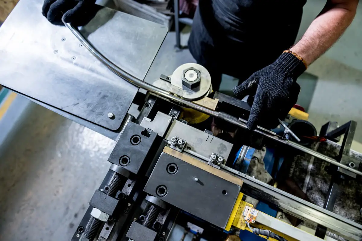
Profile bending and sheet bending have many similarities in terms of force and deformation, so problems existing in sheet bending, such as springback, also exist in profile bending.
At the same time, due to the specific cross-sectional shape of profiles, many problems that do not occur in sheet metal bending arise. These defects mainly manifest as: a) Springback; b) Wrinkling; c) Cracking; d) Cross-sectional distortion; e) Twisting; f) Collapse, etc. Specific forms are shown in Figure 4-19. Here, only some of the main defects, their causes, and prevention methods are introduced.
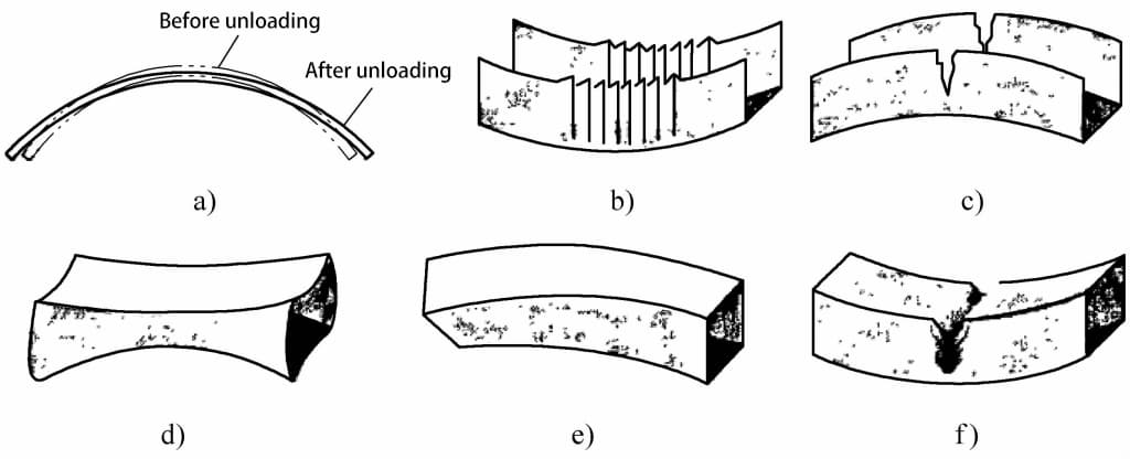
a) Springback
b) Wrinkling
c) Cracking
d) Cross-sectional distortion
e) Twisting
f) Collapse
1. Springback
The issue of springback has already been detailed previously, and will not be repeated here.
2. Wrinkling
When the profile section is large and the process parameters are not set reasonably, wrinkling can occur on the inner wall after the profile is bent. The reason for wrinkling is that during the bending process of the profile, the part below the neutral layer is subjected to longitudinal compressive stress, and is also subjected to compressive stress in the radial and width directions. Under the action of three-way compressive stress, it is easy to produce longitudinal shrinkage and radial thickening deformation, which can cause wrinkling when severe.
In stretch bending, if sufficient pre-tension is applied to the profile before bending, wrinkling can be avoided. Additionally, increasing the post-bending tension can also eliminate wrinkling. Furthermore, in terms of molds, measures such as adding limit slots and using mandrels can be adopted to prevent wrinkling.
Many scholars have studied this issue. Studies have shown that the width-to-thickness ratio (b/t) of rectangular section profiles and the width of the profiles are the main factors affecting the occurrence of wrinkling, and the impact of material properties on wrinkling is also quite significant.
In addition, the scholars pointed out that the wrinkling instability of the inner side web of the profile is similar to the compression instability at both ends of the thin-walled shell. It is not only related to the magnitude of the compressive stress but also to the ratio of the thickness to the width of the profile. The smaller the ratio, the more likely it is to experience wrinkling instability; increasing the thickness of the inner side web of the profile can improve its anti-wrinkle ability.
Some other scholars pointed out that the wrinkling of the inner wall is related to various factors such as the bending radius, material properties, and cross-sectional shape, and can be effectively controlled by adjusting the amount of pre-stretching. The current research results provide some basic methods for eliminating wrinkling. However, the cross-sectional shape of the profile is diverse, and the wrinkling phenomenon is complex, requiring further in-depth study.
1. Rupture
In cases where the bending radius is too small, or additional tangential tensile force is added to reduce springback and prevent inner wall wrinkling, there is a significant tensile stress on the profile section, especially on the outer side wall, causing excessive thinning of the outer side wall thickness, or even rupture. When the profile section is taller and the bending radius is smaller, the phenomenon is more severe. In the profile bending forming process, thinning and rupture of the outer side wall is one of the manifestations of the limit of profile bending forming.
For the problem of thinning and rupture of the outer side wall during bending, the main measures are to anneal the tube to reduce hardness. At the same time, strictly control the surface quality of the tube; adjust the boosting speed or rotation speed; check whether the mandrel size or position is appropriate; check whether there is oil on the surface of the clamp mold and the press mold, clean the surface; check whether the gap between the press mold and the anti-wrinkle mold, wheel mold is appropriate, adjust accordingly; check whether the pressure of the press mold and clamp mold is appropriate, adjust accordingly.
4. Sectional distortion and inner side wall wrinkling
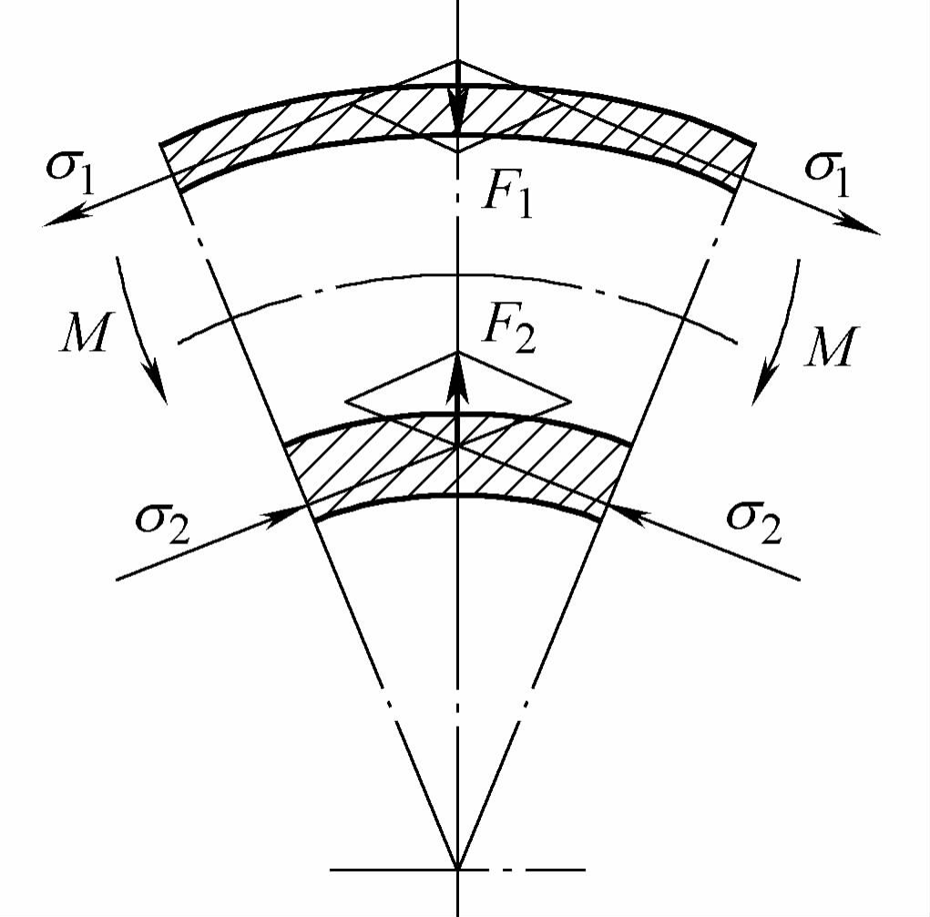
As shown in Figure 4-20, under pure bending, when a tube with an outer diameter D and wall thickness t is subjected to an external torque M, the tube wall on the outer side of the neutral layer is thinned under the action of tensile stress σ 1 , and the inner side wall is thickened under the action of compressive stress σ 2 (see Figure 4-21a). Because the material located on the outermost and innermost sides of the bending deformation zone is subject to the greatest tangential stress, the change in wall thickness is also the greatest (see Figure 4-21).
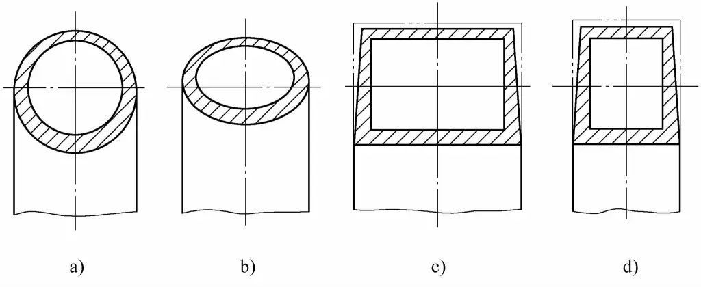
In bending with fillers or mandrels, the cross-section can basically maintain a circular shape, but the wall thickness changes. In unsupported free bending, whether it is the inner or outer side, the circular tube section becomes elliptical (see Figure 4-21b), and as the degree of bending deformation increases (i.e., the bending radius decreases), the inner side wrinkles due to instability; in supported bending of square tubes (see Figures 4-21c, d), the cross-section becomes trapezoidal. The inner side wall may also experience instability and wrinkling under the action of σ 2 (see Figure 4-19c).
(1) Distortion of circular pipe cross-section
Regarding the change of circular pipe cross-section, ellipticity is commonly used in production to measure.
Ovality = (Dmax−Dmin) / D × 100%
Where
- D max – maximum outer diameter size measured in any direction of the same cross-section of the pipe after bending;
- D min – minimum outer diameter size measured in any direction of the same cross-section of the pipe after bending.
Figure 4-22 shows the ellipticity line chart, which represents the change of ellipticity with respect to the dimensionless curvature R 0 /R (R 0 is the outer radius of the pipe, R is the curvature radius of the center layer of the bent section) on a logarithmic coordinate, represented by a family of straight lines with the ratio t/R 0 as the parameter.
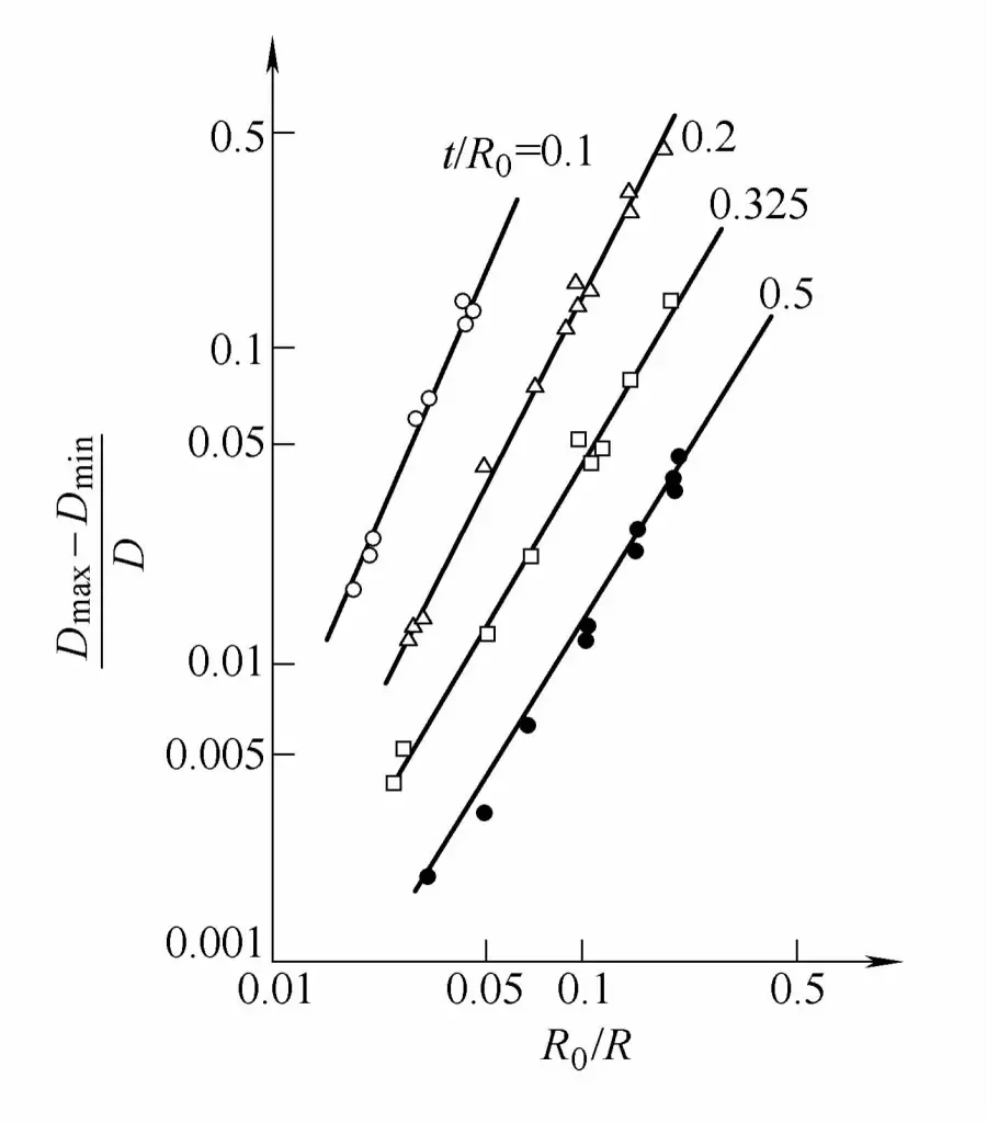
It can be seen from the figure that the greater the degree of bending, the greater the ellipticity of the cross-section. Therefore, ellipticity is commonly used in production as an important indicator to inspect the quality of bent pipes. Depending on the performance requirements of the bent pipe components, the requirements for their ellipticity also vary.
For example, in industrial pipeline engineering, the ellipticity of bent pipe components should not exceed 5% for high-pressure pipes; 8% for medium and low-pressure pipes; 9% for aluminum pipes; 8% for copper alloy and aluminum alloy pipes. In agricultural machinery, the ellipticity of bent pipe components should not exceed 5%.
The distortion of the cross-sectional shape may cause a reduction in the cross-sectional area, increase the resistance to fluid flow, and also affect the functional effect of the pipe components in the structure. Therefore, in the bending processing of pipe components, measures must be taken to control the amount of distortion within the required range.
Currently, there are mainly two methods to eliminate or reduce distortion. One is to determine the profile section shape based on the structure and processability of the profile parts; the other is to support the profile during the production process (by adding a core rod or filler) to increase the stiffness of the profile section.
1) Support the section with a core rod in the bending deformation area to prevent section distortion.
2) Filling the bending billet with granular media, fluid media, elastic media, or low-melting-point alloys can also replace the core rod to prevent section shape distortion. This method is relatively easy to apply and is widely used, especially in small and medium batch production.
3) On the mold surface in contact with the tube material, grooves that match the section shape of the tube are made to reduce the pressure on the contact surface and hinder the section’s twisting, which is a quite effective measure to prevent section shape distortion.
4) Use the reverse deformation method to control the change of the tube section (see figure 4-24), this method is commonly used in the coreless bending process on bending machines, characterized by its simple structure, thus widely applied.
Using the reverse deformation method for coreless bending (see figure 4-23), that is, the billet is given a certain amount of reverse deformation in advance, then after bending, due to the mutual cancellation of deformations in different directions, the billet section is basically maintained round, to meet the requirements of ovality, thereby ensuring the quality of the bending.
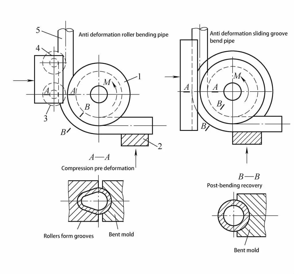
1—Bending mold
2—Clamping block
3—Roller
4—Guide Wheel
5—Pipe Blank
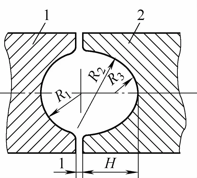
The cross-sectional shape of the anti-deformation groove is shown in Figure 4-24, and the size of the anti-deformation groove is related to the relative bending radius R/D (R is the curvature radius of the central layer, D is the outer diameter of the pipe). The dimensions of the anti-deformation groove are shown in Table 4-5.
Table 4-5 Dimensions of the Anti-Deformation Groove
| Relative curvature radius R/D | R1 | R2 | R3 | H |
| 1.5~2 | 0.5D | 0.95D | 0. 37D | 0.56D |
| >2~3.5 | 0.5D | 1.0D | 0.4D | 0.545D |
| ≥3.5 | 0.5D | — | 0.5D | 0.5D |
(2) Change in Pipe Thickness
The change in pipe thickness mainly depends on the pipe’s relative bending radius R/D and relative thickness t/D. In production, the minimum wall thickness t min on the bending outer side and the maximum wall thickness t max on the inner side can usually be estimated using the following two formulas:
Where:
- t – Original thickness of the pipe (mm);
- D – Outer diameter of the pipe (mm);
- R- Bending radius of the central layer (mm).
The thinning of the pipe wall thickness reduces the mechanical strength and performance of the pipe fittings. Therefore, the wall thickness reduction rate is commonly used in production as a technical indicator to measure the change in wall thickness, to meet the performance requirements of the pipe fittings.
Where:
- t is the original thickness of the pipe material (mm);
- tmin is the minimum wall thickness of the pipe material after bending (mm).
The performance requirements for pipe materials vary, and so do the requirements for wall thickness reduction rates. For pipe fittings used in industrial pipeline engineering, the rate should not exceed 10% for high-pressure pipes; for medium and low-pressure pipes, it should not exceed 15%, and should not be less than the designed calculated wall thickness. In agricultural machinery, the wall thickness reduction rate for bent pipe fittings generally should not exceed 5%.
Measures to reduce the thinning of pipe wall thickness include:
1) Reducing the tensile stress value in the area where tensile deformation occurs on the outer side of the neutral layer. For example, by adopting the method of resistance local heating, reducing the deformation resistance of the metal material on the inner side of the neutral layer, making the deformation more concentrated in the compressed part, to achieve the purpose of reducing the stress level in the tensile part.
2) Changing the stress state of the deformation area, increasing the component of compressive stress. For example, changing from bending to push bending can fundamentally overcome the defect of excessive thinning of the pipe wall.

