Next-Gen Pipe Bending: Exploring Innovative Processes
Imagine revolutionizing the way we bend pipes, pushing the boundaries of efficiency and precision. The next generation of pipe bending…
There are many methods and devices for bending pipes. Based on whether the deformation zone is directly affected by a mold, it can be divided into mold forming and moldless forming. According to the bending temperature, it can be divided into cold bending and hot bending. Common cold bending methods include press (push) bending, roll bending, wrap bending, and extrusion bending.
Press (push) bending is achieved by lateral plastic bending on a press or push bending machine; roll bending is achieved by adding molds on a plate rolling machine or by continuous point-by-point lateral plastic bending on a profile bending machine; extrusion bending is achieved by extrusion bending on a press or a dedicated extrusion machine; wrap bending is achieved on a vertical or horizontal pipe bending machine by bending with a certain tensile force.
The main methods of hot bending of pipes include medium frequency pipe bending and flame bending, which is a process of continuous heating, bending, and cooling of pipes on specialized equipment. Based on the form of force applied during bending, it can be divided into pull bending and push bending. Additionally, laser moldless bending can be achieved by controlling thermal stress through localized transient heating with lasers.
Wrap bending on pipe bending machines is widely used in industries such as boilers, shipbuilding, automotive, and aerospace due to its precise forming, small bending radius, bending angles of over 180 degrees, resistance to wrinkling, continuous bending capability, and ease of CNC integration. Below, only the wrap pull bending pipe machine (hereinafter referred to as the pipe bending machine) is introduced.
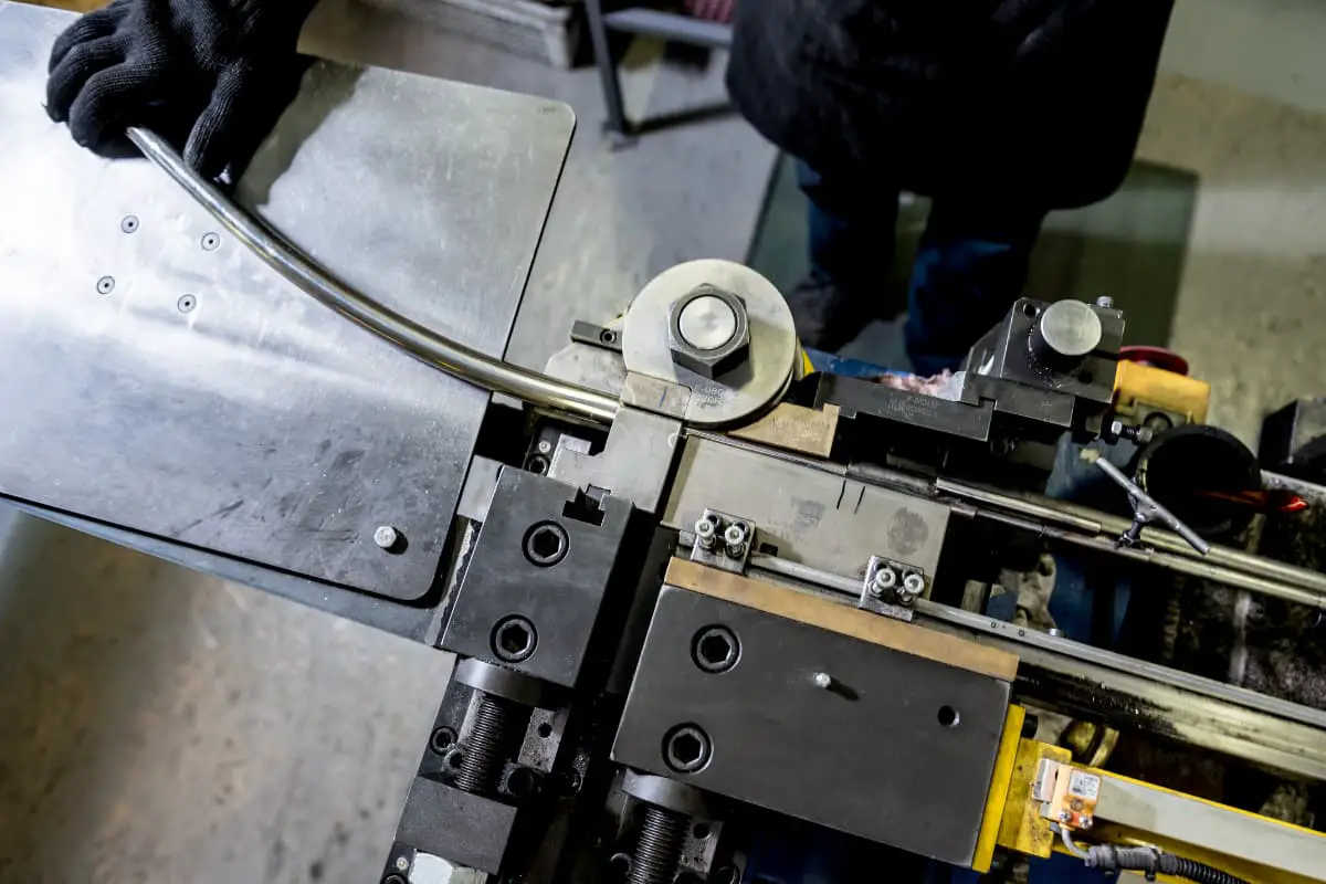
As shown in Figure 1, the pipe bending die with a semicircular groove is rotated by a hydraulic cylinder through a sprocket, chain, and main shaft. The pipe is placed inside the bending die and clamped by the clamping die. A guiding device (roller or groove) is used to press the outer surface of the pipe in the deformation area.
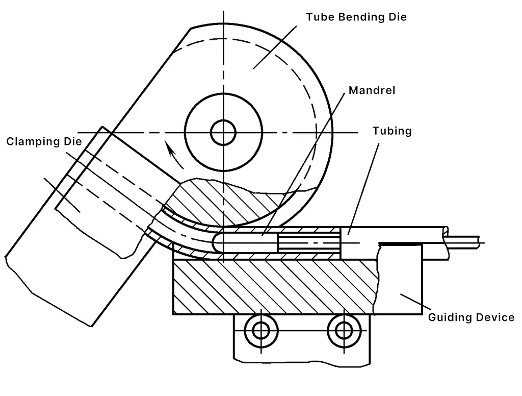
A mandrel head installed on the mandrel device extends into the inner hole of the pipe, located at or slightly ahead of the centerline of the bending die. When the pipe is clamped by the clamping die and rotates together with the bending die, it bends tightly against the bending die.
When the pipe has different diameters and bending radius requirements, a different bending die is needed. The bending angle of the pipe is controlled by a mechanical stop block (or digital display), and when the bending die rotates to a certain angle, it hits the stop block (or programmer) which sends a command to stop the hydraulic cylinder, thus stopping the bending die and completing the required pipe bend.
Common forms of pipe bending machines mainly include: hydraulic (planar) pipe benders, CNC (three-dimensional, single-mode) pipe benders, and CNC dual-mode (or multi-mode) pipe benders. Additionally, there are CNC push bending machines, CNC double-head pipe benders, CNC serpentine pipe benders, and pipe arrangement benders.
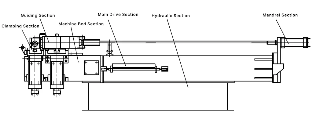
Figure 2 shows the structural composition of the hydraulic (planar) pipe bender. The machine consists of a bed, main drive, clamping, guiding, mandrel, and electrical and hydraulic control systems. It is generally used for bending two-dimensional planar pipe shapes with a single curvature radius. With additional auxiliary devices, it can also bend spatial pipe shapes.
This type of machine can bend single-curvature radius tubes in three-dimensional space, and its structural composition includes the basic structure of the aforementioned hydraulic tube bender. Additionally, its most typical structure is that the machine has three motion coordinate axes: the Y-axis for linear feed distance, the B-axis for tube space rotation angle, and the C-axis for tube plane bending angle.
All three coordinate axes are precisely controlled by a computer, with the Y and B axes driven and controlled by AC servo motors or hydraulic servo motors. The C axis is driven and controlled by an electro-hydraulic servo valve. Smaller CNC tube benders have all three axes controlled by electric servos.
Figure 3 shows the assembly positions of the motion coordinate axes and molds of the CNC tube bender. The CNC tube bender system features a touch screen display terminal that can input and display various tube bender data and commands. The screen can switch its working state and has strong editing capabilities, allowing operators to freely select and call up various motion speeds for each motion coordinate axis and store them in memory.
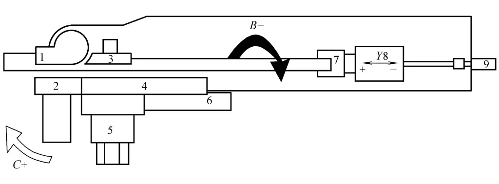
1—Bending mold
2—Clamp
3—Anti-wrinkle plate
4—Guide plate
5—Guide slider
6—Cylinder block
7—Collet
8—Trolley
9—Core rod hydraulic cylinder
The machine’s good editing capabilities allow the operator to add or modify tube data in the program. Compensation for springback occurring during tube bending is achievable. The computer also features safety locks and diagnostic functions, automatically locking the machine and displaying diagnostic results in case of operational errors or other issues.
This type of machine can bend tubes with two or more curvature radii in space.
In addition to the structural features of CNC and hydraulic tube benders, it also adds movements of the “X-axis” and “Z-axis”. The X-axis changes the bending radius, achieved by lateral movement of the bending head or the feed tailstock. The drive and control of the X-axis are accomplished by an AC servo motor.
Z-axis—a vertical lifting axis. Core shaft, sleeves move up and down for positioning on the molds used during bending. Driven by hydraulic servo or electric servo.
The parameters of the hydraulic pipe bending machine and the CNC pipe bending machine are implemented according to the JB/T2671.1—1998 “Pipe Bending Machine Parameters” and JB/T5761—1991 “CNC Pipe Bending Machine Parameters” standards.