Plasma Cutting and Laser Cutting Explained
How do plasma cutting and laser cutting stack up against each other? Plasma cutting offers speed and efficiency for thick…
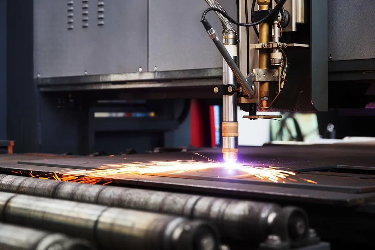
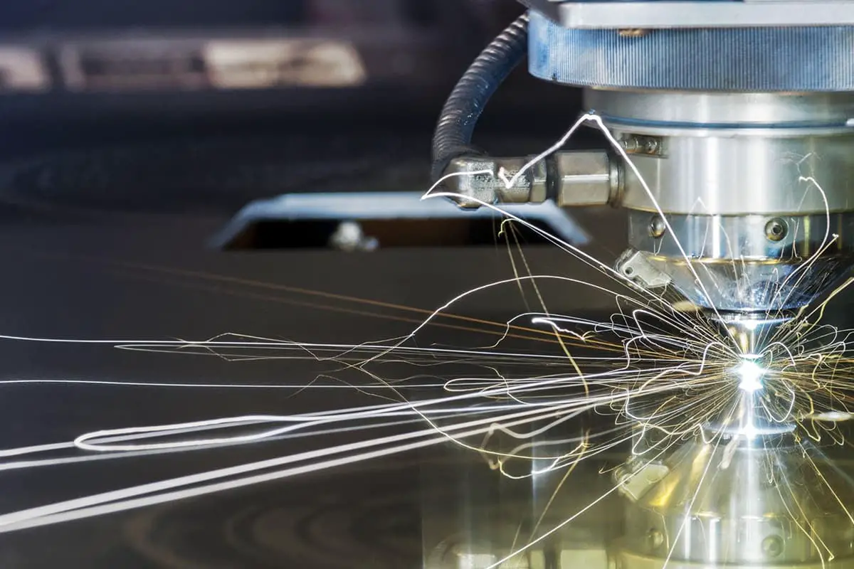
How can a machine harness the power of plasma to cut through metal with precision? Plasma cutting machines offer a fascinating solution, using high-temperature plasma arcs to slice through various metals swiftly and efficiently. This guide delves into how plasma cutting works, the different types of plasma cutting methods, and the key components of these machines. Whether you’re a novice or an expert, you’ll learn about the advantages, limitations, and best practices for utilizing plasma cutting technology to achieve clean, precise cuts.
Plasma cutting uses the high energy density of the plasma arc and the high-speed plasma flow to melt and vaporize the metal at the cutting point under the high temperature of 10000~14000℃, and blow the melted metal away from the cut.
The plasma arc uses a plasma gun to compress the free arc between the cathode (such as a tungsten electrode) and the anode into a high-temperature, high ionization, high energy density, and high flame velocity arc, as shown in Figure 1.
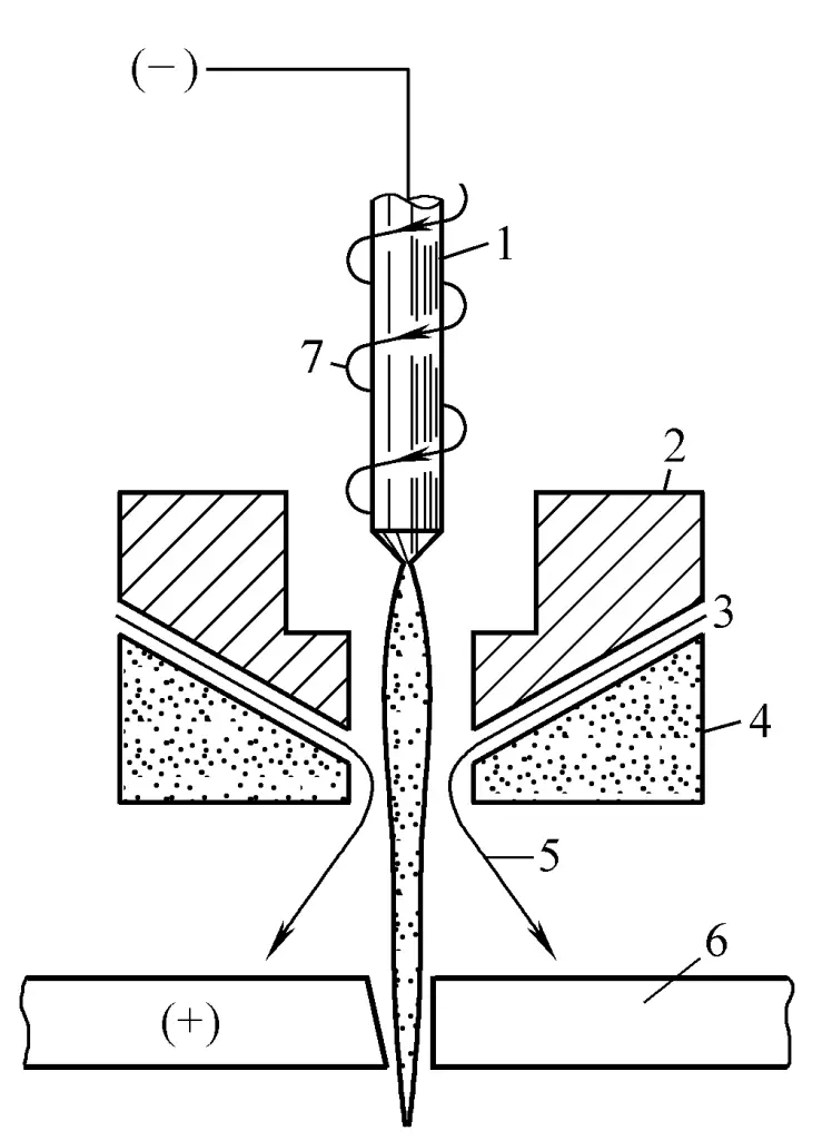
1—Electrode
2—Nozzle (Copper)
3—Water
4—Nozzle (Ceramic)
5—Water jet
6—Workpiece
7—Working gas
When the electrode is connected to the negative pole, the workpiece is connected to the positive pole and an appropriate voltage is applied, the electrode connected to the negative pole emits electrons to the workpiece connected to the positive pole, and at the same time, working gas is introduced through the nozzle. Under the impact of the high-speed electron stream, the molecules and atoms of the neutral gas gain a great amount of energy and are ionized, producing negatively charged electrons and positively charged ions.
The formed electrons, ions, and the still non-ionized neutral gas molecules and atoms collide with each other, and the heat and light produced by the ionized atoms further ionize the gas. This cycle repeats, causing avalanche ionization and forming a plasma arc.
Due to the effect of the nozzle’s constriction, a “mechanical compression effect” is formed on the arc column, increasing the energy density of the arc column; and due to the “magnetic pinch effect” produced by the magnetic field of the arc column itself, the diameter of the high-temperature plasma arc becomes finer, the energy density increases, and the gas ionization is sufficient.
Also, because the high-temperature electric arc causes the accompanying high-speed water jet to vaporize quickly, a vapor layer forms a “vapor jacket” with a large temperature gradient on the periphery of the plasma arc, further enhancing the “thermal contraction effect” and greatly increasing the energy density of the electric arc, forming a plasma arc with extremely high temperature, good stiffness, and high flow rate.
Some water decomposes into H2 and O2 at high temperatures, which together with the working gas form the cutting gas, giving the plasma arc higher energy. The working gases used are mainly oxygen, nitrogen, and air.
The injected water not only acts to compress the arc column making it thinner but also cools the nozzle and the workpiece, reduces the production of nitrogen oxide, improves the life of the nozzle, and reduces the heat-affected zone of the workpiece. The injected water should be softened.
(1) Plasma can cut any ferrous and non-ferrous metals, as well as some non-metallic materials.
(2) When cutting metals of not great thickness, the cutting speed is fast. For example, when cutting a 6mm steel plate, the cutting speed can reach 6m/min, which is 6 times the speed of 1kW laser cutting and 10 times the speed of gas cutting.
(3) Due to the high temperature and high energy density of the plasma arc, the arc column is straight and stable, so plasma cutting can achieve relatively narrow, clean, neat, burr-free, and almost vertical cuts. However, the quality of the cut is still inferior to laser cutting, with the cut having a slope. The heat-affected zone near the cut is small.
(4) The cutting cost is relatively low, about one-fifth of gas cutting and laser cutting when cutting 6mm steel plates.
(5) The main disadvantages are high noise, as well as smoke, dust, and arc radiation.
According to the different working gases used, it can be divided into four categories, namely oxygen plasma cutting, air plasma cutting, nitrogen plasma cutting, and argon-hydrogen plasma cutting. Among them, air and oxygen belong to the same category, but oxygen has higher efficiency and better cut quality, though at a higher cost than air.
Comparison of various plasma cutting methods as shown in Table 1.
Table 1 Comparison of various plasma cutting methods
| Argon, hydrogen plasma | Nitrogen plasma | Oxygen plasma | |
| Cutting materials | Stainless steel, aluminum, copper | Steel, stainless steel, aluminum | Thin steel plate, high strength steel, coated steel plate |
| Deslagging | Not good | Not good | Good |
| Cutting plate thickness/mm | 4~150 | 0.5~100 | 0.1~40 |
| Cutting surface quality | Relatively good, no nitriding | Bad, nitrided | Good, no nitriding |
| Electrode material | Tungsten | Tungsten | Hafnium |
| Electrode life | Long | Long | Short |
For general cutting of carbon steel and low alloy steel, oxygen plasma arc with water jet is used; for cutting stainless steel and aluminum alloy, ammonia plasma arc with water jet is used. When cutting with oxygen and air plasma arc, due to the strong oxidation corrosion of the electrode, embedded pure zirconium or pure hafnium electrodes should generally be used, instead of pure tungsten or tungsten oxide electrodes.
The cut width of plasma arc cutting is 1.5 to 2 times wider than that of oxy-acetylene cutting, and the cut width increases with the thickness of the plate. During plasma arc cutting, the upper part of the cut often removes more metal than the lower part, making the end face of the cut slightly inclined. However, for cutting plates less than 8mm, especially thin steel plates, a very good cut can be obtained.
(1) When cutting carbon steel and low alloy steel with oxygen and water jet plasma arc, the cutting surface is quite smooth, with a roughness value generally lower than 20μm.
(2) Stainless steel cut with argon-hydrogen plasma arc can obtain a smooth cutting surface, cutting with nitrogen plasma arc results in greater roughness, and cutting with oxygen plasma arc is slightly rougher, but generally lower than 110μm.
(3) For aluminum and aluminum alloys, the roughness when cutting with nitrogen plasma arc is much greater than when using argon-hydrogen mixed gas, and when cutting with oxygen plasma arc, the cutting surface is rougher. However, a smooth cutting surface can be obtained with water jet plasma arc cutting.
When cutting medium thickness stainless steel plates with water jet plasma arc, the width of the heat affected zone is only 0.02mm.
In production, plasma arc cutting can now be used to cut stainless steel with a thickness of 100~200mm, but the power should be relatively large, such as for cutting materials with a thickness of over 80mm, generally 50~100kW. Preheating is required before cutting starts, for example, for stainless steel, when the workpiece thickness is 200mm, it should be preheated for 8~20s, and for a thickness of 50mm, preheat for 2.5~3.5s.
The optimal distance between the nozzle and the surface of the workpiece can refer to Table 2, and the appropriate cutting speed can refer to Table 3.
Table 2 Optimal Distance Between Nozzle and Workpiece Surface (Trumpf)
| Material Thickness/mm | Nozzle Size/mm | Nozzle Distance/mm |
| 1~2 | 3.05 | 3 |
| 3 | 3.05 | 5 |
| 6 | 3.05 | 6 |
| 3~12 | 4.2 | 6.3 |
| 19 | 4.2 | 8 |
| 25 | 4.2 | 9.5 |
Table 3 Technical Parameters for Plasma Cutting of Mild Steel (Trumpf)
| Material Thickness/mm | Nozzle size/mm | Nozzle distance/mm | Cutting gas | Gas flow adjustment range | Water flow adjustment range | Cutting speed/(m/min) |
| 1 | 3.05 | 3 | N2 | 35% | 85% | 10 |
| 2 | 3.05 | 3 | N2 | 35% | 85% | 8.5 |
| 4 | 3.05 | 3 | N2 | 35% | 85% | 5.5 |
| 6 | 3.05 | 3 | N2 | 35% | 85% | 4.4 |
| 6 | 4.2 | 5 | N2 | 45% | 75% | 4.25 |
| 8 | 4.2 | 6 | N2 | 45% | 75% | 4.2 |
| 10 | 4.2 | 6 | N2 | 45% | 75% | 3.5 |
| 12 | 4.2 | 6 | N2 | 45% | 75% | 2.8 |
| 2 | 2.5 | 3 | O2 | 36% | 100% | 12 |
| 4 | 2.5 | 3 | O2 | 36% | 100% | 8 |
| 6 | 2.5 | 3 | O2 | 36% | 100% | 6.5 |
| 8 | 2.5 | 3 | O2 | 36% | 100% | 5.5 |
| 10 | 2.5 | 3 | O2 | 36% | 100% | 2.75~4.5 |
| 12 | 2.5 | 3 | O2 | 36% | 100% | 2.75~3.5 |
The plasma cutter mainly consists of a power supply, high-frequency generator, gas supply system, cooling water system, cutting torch, system for relative movement of the workpiece, slag removal and dust removal system, and control system, etc.
Described as follows:
The working voltage and current required for power supply cutting.
The high frequency generator is used to ignite the plasma arc, usually capable of generating 3~6kV high voltage and 2~3MHz high frequency current. Once the main arc is established, the high frequency generator disconnects automatically. There is also a contact arc ignition method that does not require a high frequency generator.
The cutting torch is the main component of plasma cutting. It mainly consists of the torch body, electrode, nozzle, air and water inlet channels, and seals. The electrode is generally made of a copper electrode holder, with the electrode material (tungsten or hafnium) embedded or welded to the end. The nozzle is made of high-temperature resistant ceramics or pure copper. The form of the nozzle varies with the material, thickness, and working gas of the cutting.
The working gas (O 2 or N 2 ) required for plasma cutting demands strict purity. During water jet plasma arc cutting, the purity requirement for oxygen is 99.95%, and for nitrogen, it is 99.995%. It is usually composed of gas cylinders, gas supply pipelines, and gas valves.
The water entering the cutting torch is divided into two paths, one is the jet water used to compress the plasma arc, and the other is the cooling water, used to cool the electrode and nozzle. The water should be softened, and the cooling water can be recycled.
The plasma cutting process generates slightly toxic smoke and dust, such as nitrogen oxides, carbon monoxide, or foul odors, which are harmful to the human body. A vacuum dust extraction method should be used to effectively remove the smoke and dust. To prevent the slag produced during cutting from adhering to the surface of the workpiece, a water jet suction method can be used for slag removal. The water mixed with slag can be recycled after filtration.
The movement system of the workpiece relative to the cutting torch is a key factor in ensuring the shape and size of the cut workpiece. The workpiece is generally clamped by hydraulic tongs and driven by an AC servo motor, with a positioning accuracy of up to ±0.1mm and a repeat positioning accuracy of about 0.03mm.
Harbin Welding & Cutting Complete Equipment Company in China and Shenzhen Bolichang CNC Cutting Equipment Company both produce CNC plasma cutting machines. The average roughness of the carbon steel cutting surface is below 40um, and the dimensional accuracy of the parts is close to the lower limit of laser cutting, but the cost is only about one-fifth of it, which is very attractive for cutting thicker plates.
The German company Trumpf once produced the TrumaticPK type plasma cutting and die punching combined press, with a slider for punching and step punching on the left, and a water jet plasma cutter on the right, using the HT400 model from the American company Hypertherm. The technical parameters of the Trumatic300P series combined press are shown in Table 4.
Table 4 Technical Parameters of Trumatic 300P Plasma Punching Combined Press
| Plasma Cutting | Maximum cutting thickness / mm | 12.7 | |||||
| Maximum cutting speed / (m/min) | Cutting thickness / mm | 2 | 6 | 8 | 12 | ||
| O2 cut | 8.5 | 4.4 | 4.2 | 2.8 | |||
| N2 cut | 12 | 6.5 | 5.5 | 3 | |||
| Kerf width / mm | O2 cut——3.5 N2 cut——2.0 | ||||||
| Gas consumption / (L/min) | O2 cut——50 N2 cut——80 | ||||||
| Water consumption / (L/min) | 2~3 | ||||||
| Punching and Step Punching | Maximum Cutting Thickness/mm | Punching—12.7 | Step Punching—10.0 | ||||
| Punching Force/kN | 300 | ||||||
| Total Cutting Force/kN | 330 | ||||||
| Maximum Step Punching Frequency/(times/min) | 265~400 | ||||||
| Maximum Step Punching Speed/(m/min) | 6.6 | ||||||
| Maximum Die Diameter/mm | 105 | ||||||
| Die Change Time | Automatic——6.5s | Semi-automatic——6~12s | |||||
| Processing range/ mm | TRUMATIC 300PK | TRUMATIC 300PW | |||||
| 1600×2250 | 1600×2700 | ||||||
| Machine weight/ kg | 18500 | 20500 | |||||
| Floor space/ mm | 8010×8680 | 8010×8680 | |||||
| Positioning accuracy/ mm | ±0.1 | ±0.1 | |||||
| Minimum programmable increment/ mm | 0.01 | 0.01 | |||||
Table 5 is the technical parameters of the plasma cutting and hydraulic punching combination press produced by the American Whitney Company, which adopts a new nozzle system to improve the precision of plasma cutting.
Table 5 Whitney Plasma Combination Press Technical Parameters
| Name | Unit | Measurement | ||||
| Model | 3400RTC | 3500ATC | 3700ATC | 661ATC | ||
| Maximum punching thickness | Ordinary | mm | 12.7 | 10 | 15 | 15 |
| Add optional parts | mm | 12 | 18 | |||
| Maximum thickness for plasma cutting | mm | 12.7 | 12 | 18 | 18 | |
| Maximum weight of the plate | kg | 300 | 300 | 450 | 900 | |
| Machine positioning range | X-axis | mm | 3000 | 2280 | 3000 | 4000 |
| Y-axis | mm | 1250 | 1270 | 1600 | 1800, 2500, 3000 | |
| Automatic mold changing station | 7 | 30 | 42 | 15 or 45 | ||
| Small part drop gate size | mm | 600×1250 | 450×600 | 450×600 | 380× machine width | |
Table 6 is the technical parameters of domestic inverter air plasma cutting machines.
Table 6 Technical parameters of domestic inverter air plasma cutting machines
| Model | KL—30CW | KL—80CW | KL—160CW |
| Cutting (welding) | Cutting (welding) | Cutting (welding) | |
| Input voltage/V | 220 | 380 | 380 |
| Input power/kW | 5.2(4) | 12.5(5.5) | 25(11) |
| Number of phases | Single phase | Three phase | Three phase |
| Frequency/Hz | 50~60 | 50~60 | 50~60 |
| Output current/A | 6~30 | 10~80 | 30~160 |
| Operating voltage/V | 120(30~40) | 120(30~40) | 120(30~40) |
| Load duty cycle (%) | 60(100) | 60(100) | 60(100) |
| Air pressure/MPa | 0.4 | 0.5 | 0.6 |
| Cooling method | Air cooling | Air cooling | Air or water cooling |
| Operating mode | Contact type | Non-contact type | Non-contact type |
| Cutting thickness/mm Low carbon steel, stainless steel Aluminum Copper | 0.1~19 0.1~14 0.1~6 | 1~35 1~22 1~12 | 1~55 1~40 1~36 |
| External dimensions/mm | 200×385×325 | 285×485×515 | 380×615×620 |
| Weight/kg | 18.5 | 44 | 86 |