Top 10 Plate Rolling Machine Manufacturers in 2024
Why do some manufacturers dominate the plate rolling machine industry while others struggle? This article dives into the top 10…
Bending metal plates into single or multi-curvature cylindrical or arc shapes, usually can be done by pressing or rolling.
Press bending is done on a hydraulic press or bending press with the help of molds, mainly relying on lateral plastic bending to achieve, and its bending process is a non-continuous point-by-point or segmented bending; rolling is done on a plate rolling machine by changing the relative position and rotational movement of the working rolls, causing the plate to undergo three-point continuous bending and produce plastic deformation in a free state.
Rolling compared to press bending has the following characteristics:
① Its bending process is a continuous elastoplastic bending with a certain tensile force, with less springback, thus resulting in accurate forming, high bending quality, and high work efficiency.
② No need for molds, low usage cost.
③ The force required for rolling is often smaller than that for press forming, making the cost of plate rolling machines lower than hydraulic presses.
④ Equipped with a laying aid device, it can roll conical parts and can realize bending and rolling of pipes and profiles.
Therefore, plate rolling machines are widely used in industries such as boilers, shipbuilding, petroleum, chemical, hydroengineering, metal structures, and other machinery manufacturing. The bending and rolling of metal plates on a plate rolling machine is based on the principle of forming a circle with three points, using the relative position change and rotational movement of the working rolls to produce continuous elastic-plastic bending of the plate to obtain a workpiece of the predetermined shape.
The plate is fed between the upper and lower rolls, and the upper or lower roll is moved forcefully to produce plastic deformation and bending of the plate. When the drive work roll rotates, due to the frictional force between the work roll surface and the bent plate, the plate is bent along its longitudinal direction. The plate successively obtains plastic bending deformation of the same curvature. The principle of the plate rolling process is shown in Figure 5-6-1.
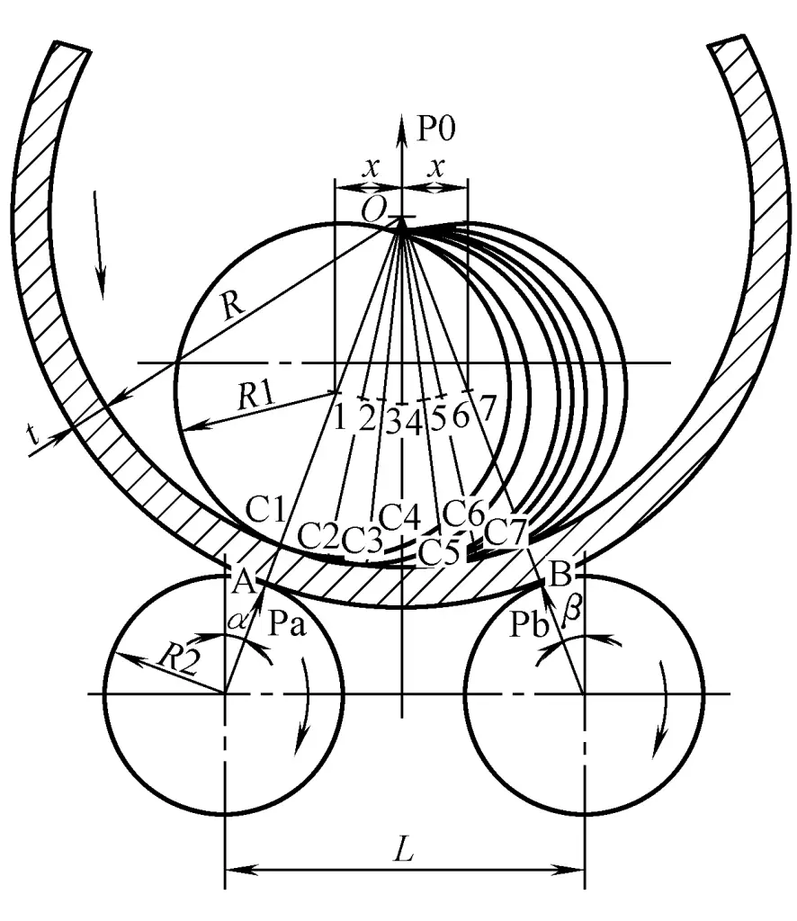
By adjusting the relative position of the working rolls, different bending radii can be obtained. However, if the envelope line formed by the displacement of a certain working roll coincides with the inner or outer surface of the drum, such as when the center of the upper roll moves arbitrarily between positions 1 to 7, then the curvature of the cylinder does not change.
It is worth noting that only when the axis lines of the upper and lower rolls and the central line of the cylinder are in the same plane, that is, when the upper roll is clamped at points C1 or C7, can the left or right end of the cylinder be well bent.
The maximum bending deformation of the plate passing through the work roll each time is limited by the meshing force. Therefore, for workpieces with a relatively small bending radius (the ratio of the bending radius to the plate thickness, i.e., R/t), it is necessary to adjust the relative position of the working rolls several times, making the plate pass through the roll axis several times, increasing the bending degree each time, until the required rolled workpiece is obtained.
In fact, the minimum bending radius is limited not only by the diameter of the upper roll and the amount of springback but also by the stiffness of the roll shaft, the power of the machine, and the limitation of metal cold work hardening. For steel plates with a relative thickness (the ratio of plate thickness to twice the bending radius t/2R) greater than 3%, warm rolling or hot rolling is usually adopted.
The commonly referred to plate rolling machine refers to a roller plate rolling machine whose main working parts are rollers parallel to each other.
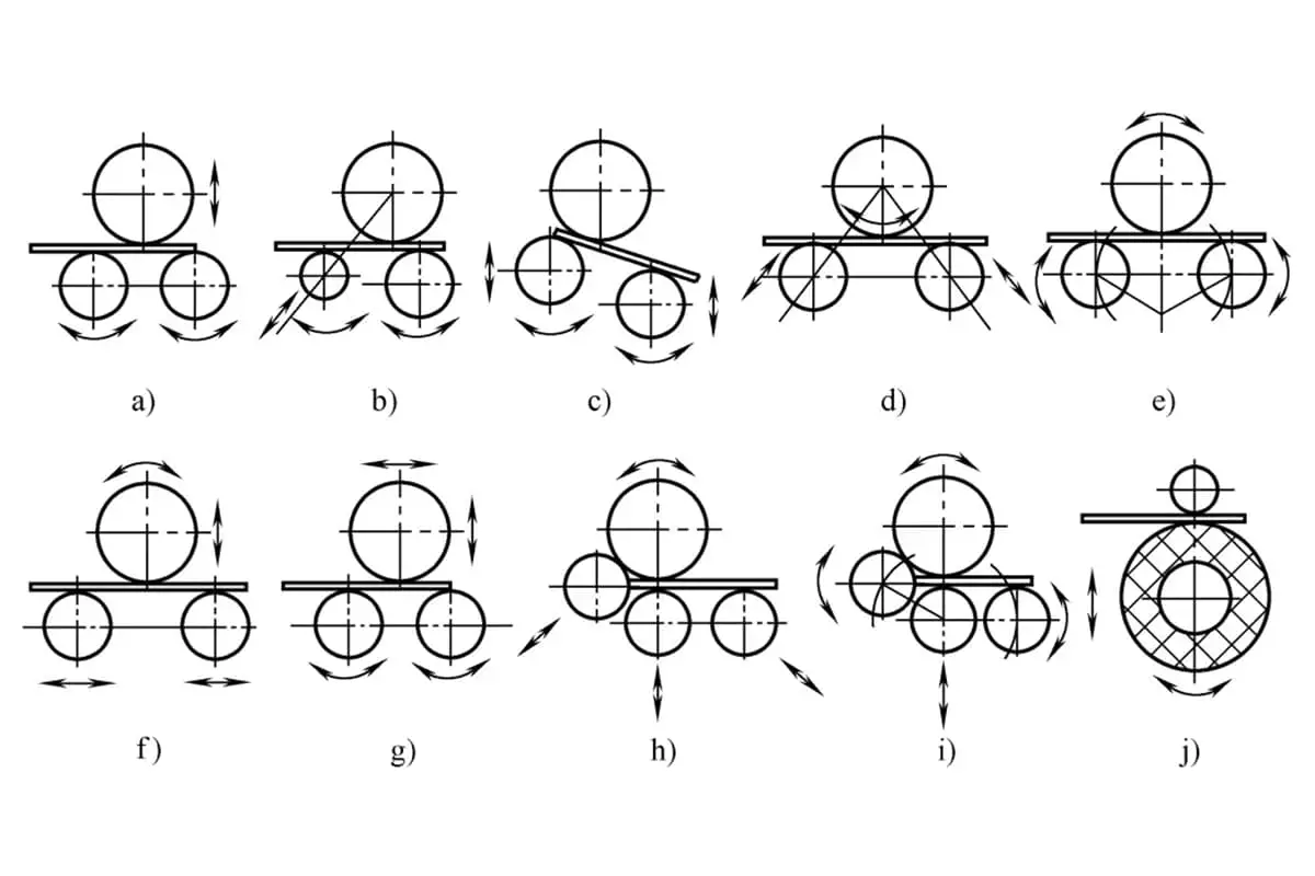
Plate rolling machines are classified into several types based on the number of working rolls, their arrangement, and the method of position adjustment, as shown in Figure 2.
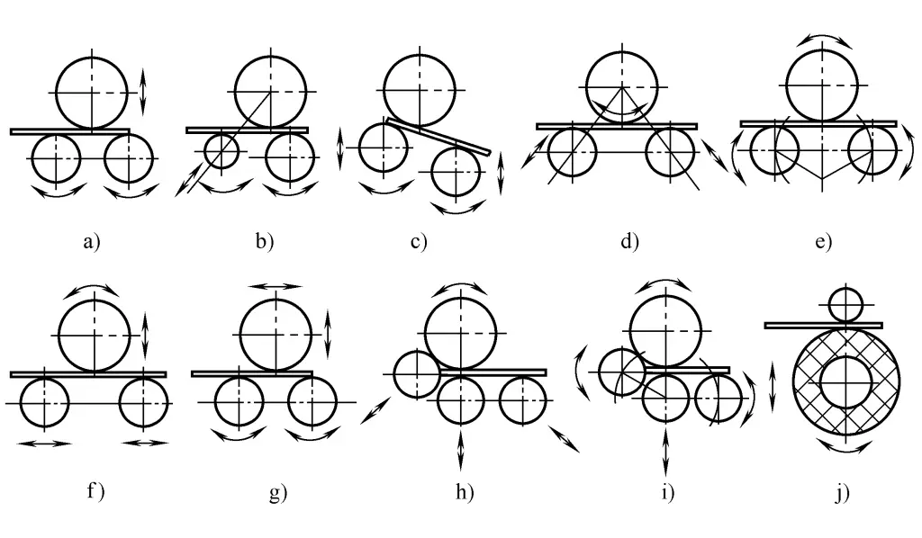
a) Symmetrical three-roll plate rolling machine
b) Asymmetrical three-roll plate rolling machine
c) Vertical downward adjustment three-roll plate rolling machine
d) Inclined downward adjustment three-roll plate rolling machine
e) Arc downward adjustment three-roll plate rolling machine
f) Horizontal lower-adjustment three-roller plate bending machine
g) Upper roll cross movement three-roll plate rolling machine
h) Inclined downward adjustment four-roll plate rolling machine
i) Arc-down style four-roller plate bending machine
j) Two-roller plate bending machine
(1) Symmetrical up-adjusting three-roller plate bending machine
The three working rollers of the symmetrical up-adjusting three-roller plate bending machine are arranged symmetrically in a “品” shape (see Figure 2a). The upper roller can move up and down to accommodate different bending radii requirements and can apply bending pressure to the plate. The lower rollers rotate in the same direction to feed the plate.
When bending the plate, the centers of the two lower rollers are fixed, so there is a remaining straight edge at both ends of the plate approximately equal to half the distance between the centers of the two lower rollers. Cylindrical parts require pre-bending of the plate ends with special equipment and molds before rolling.
(2) Asymmetrical down-adjusting three-roller plate bending machine
The asymmetrical down-adjusting three-roller plate bending machine is characterized by the asymmetrical arrangement of the working rollers (see Figure 2b). The vertical planes formed by the axes of the upper and lower working rollers have a relatively small offset distance, and the lower working roller can move vertically, while the side working roller can tilt and move vertically.
During operation, the plate ends before or after the clamping point of the upper and lower rollers are very short, with the remaining straight edge generally only reaching twice the nominal plate thickness, resulting in good pre-bending effects. However, the other end of the pre-bent plate must be turned around.
(3) Down-adjusting three-roller plate bending machine
The down-adjusting type is a modification and development of the asymmetrical down-adjusting type. According to the adjustment method of the lower roller, there are four types: vertical down-adjusting, inclined down-adjusting, solitary line down-adjusting, and horizontal down-adjusting (see Figures 2c, 2d, 2e, 2f).
1) Vertical down-adjusting and inclined down-adjusting are similar types of plate bending machines. The upper roller is fixed to rotate, only the motion trajectories of the two lower rollers are different, one moves vertically and the other moves in an inclined manner. By adjusting the relative positions of the two lower rollers to the upper roller, the workpiece can be loaded and unloaded once to complete bending and pre-bending of the front and rear plate ends.
2) Arc-down adjusting is a new structure that integrates vertical down-adjusting and inclined down-adjusting. The upper roller is fixed to rotate, the two lower rollers are drive rollers and move in an arc around a fixed axis, making the plate bending force reasonable. The workpiece can be loaded and unloaded once to complete bending and pre-bending of the front and rear plate ends.
3) The upper roller of the horizontal down-adjusting can move up and down, and the two lower rollers can move horizontally either individually or simultaneously, with all three working rollers being drive rollers or the two lower rollers being drive rollers.
During the rolling process, the two lower rollers move horizontally, each lower roller alternately performs the function of the lower roller and the side roller, that is, they successively form an asymmetric three-roller plate bending machine, thus only one loading and unloading of the workpiece is required to complete the pre-bending work of the front and rear plate ends. It is not only suitable for medium and small plate rolling machines, but also for large plate rolling machines.
4) Upper roller cross-moving type three-roller plate rolling machine. The upper roller of the upper roller cross-moving type three-roller plate rolling machine can move up and down vertically, and can also move horizontally
(see figure 2g). The pre-bending is achieved by moving the upper roller horizontally, making the upper roller asymmetrically arranged relative to the lower roller. This machine only needs to adjust the upper roller when operating, which is relatively simple. It is mainly used for medium and small plate rolling machines.
5) Four-roller plate rolling machine. The four-roller plate rolling machine generally has the upper roller as the main drive, but also has both the upper and lower rollers as the main drive, or even all four rollers as the main drive, with the upper roller fixed for rotation, and the lower roller can move up and down vertically. According to the lifting trajectory of the side rollers, the main forms of the four-roller plate rolling machine are two types: inclined downward adjustment and arc downward adjustment (see figures 2h, 2i). When adjusting one of the two side rollers respectively, it forms an asymmetric downward adjustment three-roller plate rolling machine. When rolling thicker plates, the working rollers can also work in a symmetrical arrangement. Therefore, it can be considered as a combination of symmetrical and asymmetric downward adjustment three-roller plate rolling machines.
The four-roller plate rolling machine can roughly level the plate material. At the same time, the adjustment of the position of the two side rollers by tilting can easily roll conical cylinders. In addition, the side rollers can also play a role in feeding the material. When pre-bending and rolling circular plates, there is no need to turn the head for one-time forming, and the remaining straight edge of the pre-bent plate is small; the upper and lower rollers can clamp the steel plate, which can prevent slipping, facilitate the shaping bending and bending of elliptical workpieces, and is easy to achieve numerical control.
6) Two-roller plate rolling machine. The two-roller plate rolling machine bends the metal plate by pressing it radially into a concave deformation on an elastic roller with a rigid roller, and then the two rollers roll to achieve the bending of the plate (see figure 2j).
Its advantages are: high rolling precision, high efficiency; can pre-bend the plate ends; can roll various materials, and can bend plates that have been punched, butt welded, embossed, as well as various types of steel, multi-layer steel plates, corrugated steel, metal wire mesh, etc. The disadvantage is that when rolling plates of different diameters, it generally requires changing the corresponding upper roller or roller sleeve; and it can generally only roll thin plates less than 6~10mm.
7) Closed (marine) three-roller plate rolling machine. In the shipbuilding and aerospace industries, closed (marine) plate rolling machines are commonly used, as their plate rolling width usually reaches 8~16m, or even more than twenty meters, so their upper and lower rollers often have support rollers and beams, with the upper roller in a closed structure, without a dumping discharge mechanism.
It can roll various curvatures of arc shapes and a certain range of conical workpieces, and the rolling of whole circular workpieces can be processed by splicing two or more arc pieces together. Currently, the main types of closed plate rolling machines include symmetric upward adjustment type, horizontal downward adjustment type, upper roller cross-moving type, etc.
Symmetrical upward-adjusting roller arrangement and characteristics are the same as those of the symmetrical upward-adjusting three-roller plate rolling machine. When rolling workpieces with smaller curvature radii, it is necessary to pre-bend the plate ends, but the structure is simple and the cost is low. The horizontal downward-adjusting type can achieve arc and conical bending and pre-bending of the plate ends in one feeding. It has good structural rigidity, simple operation, convenient maintenance, and high working accuracy.
The closed (marine) upper roller cross-moving type is the application of the upper roller cross-moving three-roller plate rolling machine structure on the closed plate rolling machine, which can achieve arc and conical bending and pre-bending of the plate ends in one feeding. To achieve pre-bending of the plate, the upper working roller and support roller, upper crossbeam, left and right frames, etc., need to move together as a whole, resulting in a high center of gravity and relatively poor structural rigidity.
8) Vertical plate rolling machine. The roller axis of the vertical plate rolling machine is perpendicular to the horizontal plane, and according to the number of rollers, there are mainly vertical three-roller and four-roller plate rolling machines.
Its advantages are:
The steel plate bends in a vertical state, its own weight has little impact on accuracy, which is beneficial for the rolling of thin-walled large-diameter and narrow and long workpieces; rust and iron filings during rolling will not roll into between the steel plate and the rollers, forming indentations, effectively protecting the plate surface; it occupies a small area, and it is not necessary to occupy a lot of space when removing the rolled product; after rolling, it can be directly welded in place with electroslag welding.
The disadvantages are:
In order to remove the workpiece, it is necessary to increase the workshop height; due to the friction between the lower part of the steel plate and the support surface, it is easy to form a conical shape. In addition to the above forms, in recent years, there have also been special plate rolling machines for tank trucks and multi-point flexible forming plate rolling machines.
The former is suitable for the rolling of super-wide thin plates (the ratio of plate thickness to width is very small) multi-curvature tank truck cylindrical parts, a new type of symmetrical or horizontal downward-adjusting three-roller plate rolling machine with upper roller support rollers and crossbeams, all three rollers are main drives, with a tipping discharge mechanism, capable of rolling closed cylindrical parts with a width of 8-12m; the latter combines multi-point flexible forming technology with traditional plate rolling forming technology to achieve flexible plate rolling equipment for three-dimensional curved surface flexible forming of plates.
(1) The basic parameters in JB/T8797-1998 “Types and Basic Parameters of Small and Medium-sized Three-roller Plate Rolling Machines” are shown in Table 1.
Table 1 Basic parameters of the symmetrical upward-adjusting three-roller plate rolling machine (JB/T8797-1998)
| Technical specifications | Maximum plate thickness/mm | Maximum plate width/mm | Minimum mandrel diameter at maximum size/mm | Plate yield limit/MPa | Upper roller diameter/mm | Lower roller diameter/mm | Distance between centers of lower rollers/mm | Plate rolling speed/(m/min) | Main drive motor power/kW |
| 20×2000 | 20 | 2000 | 700 | 245 | 280 | 220 | 360 | 5.5 | 15 |
| 16×2500 | 16 | 2500 | |||||||
| 12×3200 | 12 | 3200 | |||||||
| 25×2000 | 25 | 2000 | 850 | 340 | 280 | 440 | 5 | 30 | |
| 20×2500 | 20 | 2500 | |||||||
| 16×3200 | 16 | 3200 | |||||||
| 30×2500 | 30 | 2500 | 1100 | 440 | 360 | 580 | 4 | 37 | |
| 40×3200 | 40 | 3200 | 1500 | 550 | 420 | 700 | 4 | 45 | |
| 50×3200 | 50 | 3200 | 1800 | 580 | 470 | 725 | 3 | 55 | |
| 70×3200 | 70 | 3200 | 2000 | 760 | 620 | 900 | 3 | 75 | |
| 100×3500 | 100 | 3500 | 2500 | 800 | 680 | 1000 | 3 | 110 | |
| 120×3500 | 120 | 3500 | 3000 | 900 | 720 | 1200 | 3 | 180 | |
| 140×3000 | 140 | 3000 | 3500 | 950 | 760 | 1350 | 3 | 220 |
(2) See Table 2 for the technical parameters of the arc-down three-roll plate bending machine.
Table 2 Technical Parameters of Under-adjusting Three-roller Plate Bending Machine (JB/ T 10924—2010)
| Technical Specifications | 6×2000 | 12×2500 | 20×2500 | 30×2500 | 50×3200 | 60×3200 | 70×3200 | |
| Max Plate Thickness / mm | Rolling | 6 | 12 | 20 | 30 | 50 | 60 | 70 |
| Pre-bending | 3 | 8 | 16 | 20 | 40 | 50 | 60 | |
| Max Plate Width / mm | 2000 | 2500 | 2500 | 2500 | 3200 | 3200 | 3200 | |
| Min Roller Dia. at Max Specification / mm | 550 | 650 | 800 | 1200 | 4600 | 2000 | 2000 | |
| Plate Yield Limit / MPa | 245 | |||||||
| Upper Roller Dia. / mm | 220 | 280 | 330 | 460 | 640 | 680 | 720 | |
| Lower Roller Dia. / mm | 220 | 280 | 330 | 460 | 590 | 630 | 670 | |
| Roll speed/ (m/min) | 5 | 5 | 5 | 4 | 3 | 3 | 3 | |
| Main drive motor power/ kW | 5.5 | 15 | 18.5 | 22 | 55 | 55 | 75 | |
(3) Technical parameters of the horizontal down-adjustable three-roll bending machine are shown in Table 3.
Table 3 Technical parameters of the horizontal down-adjustable three-roll bending machine (JB/ T 11195—2011)
| Technical specifications | Max plate thickness/mm | Max plate width/mm | Min roll dia. at max specification/mm | Plate yield limit/ MPa | Upper roll dia./mm | Lower roller dia./mm | Plate rolling speed/(m/min) | Main drive motor power/kW | |
| Rolling | Pre-bending | ||||||||
| 80×3200 | 80 | 70 | 3200 | 2000 | 245 | 780 | 480 | 3 | 112 |
| 100×3200 | 100 | 90 | 3200 | 2000 | 860 | 480 | 3 | 155 | |
| 120×3200 | 120 | 100 | 3200 | 2500 | 950 | 500 | 3 | 210 | |
| 140×4000 | 140 | 130 | 4000 | 3000 | 1100 | 600 | 3 | 4×30 | |
| 160×3500 | 160 | 140 | 3500 | 3000 | 1200 | 600 | 3 | 4×55 | |
| 200×3500 | 200 | 180 | 3500 | 3000 | 1300 | 1050 | 3 | 4×55 | |
| 250×3000 | 250 | 230 | 3000 | 3000 | 1320 | 800 | 3 | 4×55 | |
| 300×3200 | 300 | 250 | 3200 | 4500 | 1400 | 850 | 3 | 4×55 | |
| 350×3500 | 350 | 330 | 3500 | 5000 | 1500 | 1200 | 3.5 | 4×90 | |
(4) Technical parameters of the upper roller cross-moving three-roller plate rolling machine are shown in Table 4.
Table 4 Technical parameters of the upper roller cross-moving three-roller plate rolling machine (JB/T 10292—2010)
| Technical specifications | 32×4000 | 40×4000 | 60×4000 | 100×4000 | 110×4000 | 120×4000 | |
| Max plate thickness/mm | Rolling | 32 | 40 | 60 | 100 | 110 | 120 |
| Pre-bending | 28 | 35 | 55 | 85 | 90 | 100 | |
| Max plate width/mm | 4000 | 4000 | 4000 | 4000 | 4000 | 4000 | |
| Plate yield limit/ MPa | 245 | ||||||
| Upper roller pressure/kN | 4300 | 5400 | 9300 | 16000 | 20000 | 24000 | |
| Upper roller diameter/mm | 580 | 630 | 780 | 940 | 980 | 1030 | |
| Lower roller diameter/mm | 290 | 340 | 440 | 560 | 580 | 630 | |
| Plate rolling speed/(m/min) | 4.5 | 4.5 | 4 | 3.5 | 3.5 | 3 | |
| Main drive motor power/kW | 55 | 55 | 75 | 90 | 110 | 150 | |
(5) See Table 5 for the technical parameters of the four-roll plate bending machine.
Table 5 Technical parameters of four-roll plate bending machine (JB/T 8778—1998)
| Technical specifications | Max plate width/mm | Max plate thickness/mm | Max pre-bending plate thickness/mm | Min at max specifications Roller diameter/mm | Plate yield limit/MPa | Upper roller dia./mm | Plate rolling speed/(m/min) | Motor power/kW |
| 30×3200 | 3200 | 30 | 25 | 1100 | 245 | 560 | 4.5 | 37 |
| 40×3200 | 3200 | 40 | 32 | 1200 | 245 | 660 | 4.5 | 45 |
| 50×3200 | 3200 | 50 | 40 | 1200 | 245 | 680 | 4.5 | 55 |
| 60×3200 | 3200 | 60 | 50 | 1500 | 245 | 700 | 4 | 55 |
| 70×3200 | 3200 | 70 | 60 | 2000 | 245 | 720 | 3.5 | 75 |
| 80×3200 | 3200 | 80 | 70 | 2500 | 245 | 800 | 3.5 | 90 |
| 100×3200 | 3200 | 100 | 85 | 3000 | 245 | 930 | 3.5 | 100 |
| 120×3200 | 3200 | 120 | 100 | 3000 | 245 | 950 | 3 | 150 |
| 160×4000 | 4000 | 160 | 140 | 4000 | 245 | 1260 | 3 | 350 |
(6) Closed (for ship) three-roller plate bending machine technical parameters see Table 6.
Table 6 Closed (for ship) three-roller plate bending machine parameters (JB/ T 10927—2010)
| Technical specifications | 20×8000 | 25×9000 | 20×10000 | 20×12000 | 30×13500 | 32×16000 | 35×21000 |
| Maximum plate width/mm | 8000 | 9000 | 10000 | 12000 | 13500 | 16000 | 21000 |
| Maximum plate thickness/mm | 20 | 25 | 20 | 20 | 32 | 32 | 35 |
| Maximum pre-bending plate thickness/mm | 30 | 32 | |||||
| Minimum cylinder radius at maximum specification/mm | 500 | 400 | 500 | 600 | 600 | 750 | 750 |
| Plate yield limit/MPa | 245 | 245 | 245 | 245 | 350 | 355 | 355 |
| Upper roller diameter/mm | 360 | 380 | 420 | 420 | 480 | 500 | 520 |
| Lower roller diameter/mm | 300 | 320 | 350 | 350 | 400 | 420 | 420 |
| Maximum downforce of the upper roller/kN | 2800 | 4500 | 3300 | 3800 | 13000 | 18000 | 21000 |
| Plate rolling speed/m/min | 4 | 4 | 3 | 3 | 3 | 3.4 | 3 |
| Motor power/kW | 45 | 55 | 2×22 | 2×22 | 2×55 | 2×75 | 2×90 |
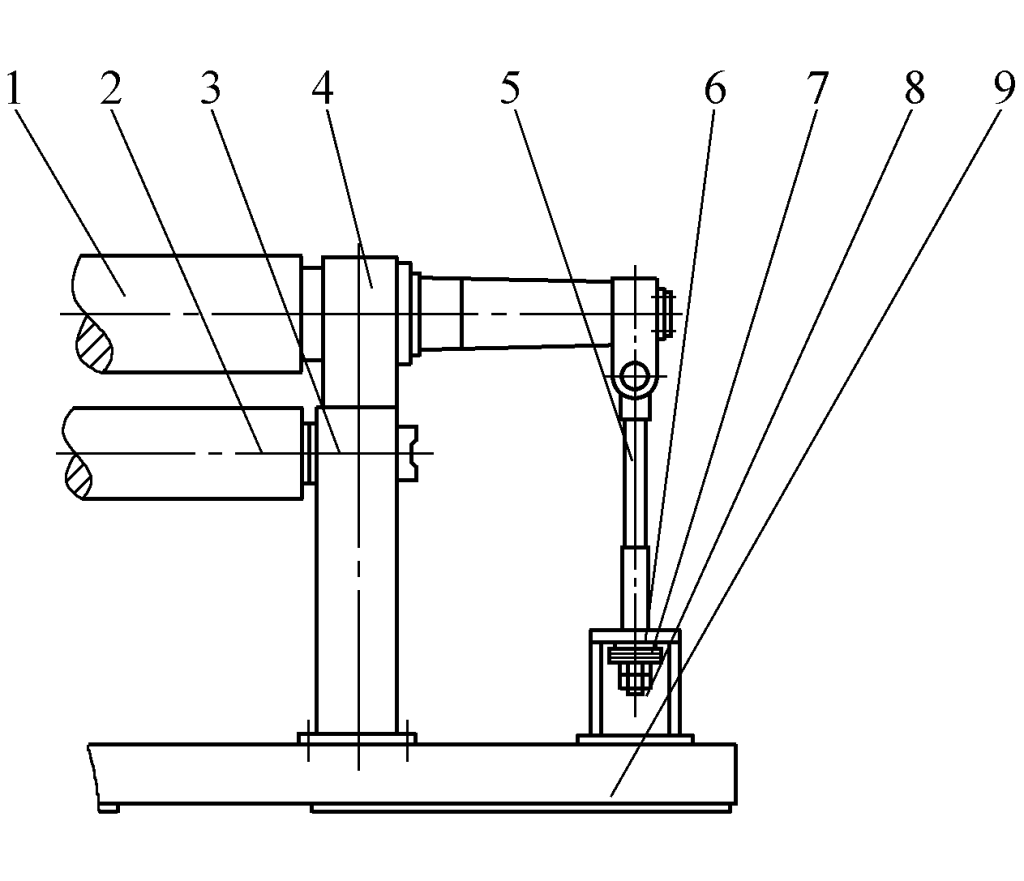
The components of a typical plate rolling machine include: frame, working rollers, main drive, tipping mechanism, lubrication system, control system, and accessories, etc.
The frame and base are made of casting or welded steel plate, the working rollers are made of high-quality medium carbon steel, alloy structural steel, or roll steel, and are tempered or surface-hardened. The supports at both ends of the working roller use self-lubricating composite material sliding bearings or rolling bearings. The use of rolling bearings can reduce friction torque and improve the overall bearing capacity of the machine.
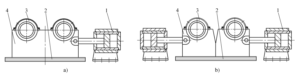
A lifting mechanism is installed on the drive side of the machine, medium and small plate rolling machines often use manual tipping mechanisms and lifting mechanisms; large plate rolling machines often use hydraulic-driven lifting mechanisms (see Figure 3), and a hydraulic-driven slide rail type tipping mechanism is installed on the discharge side of the machine (see Figure 4).
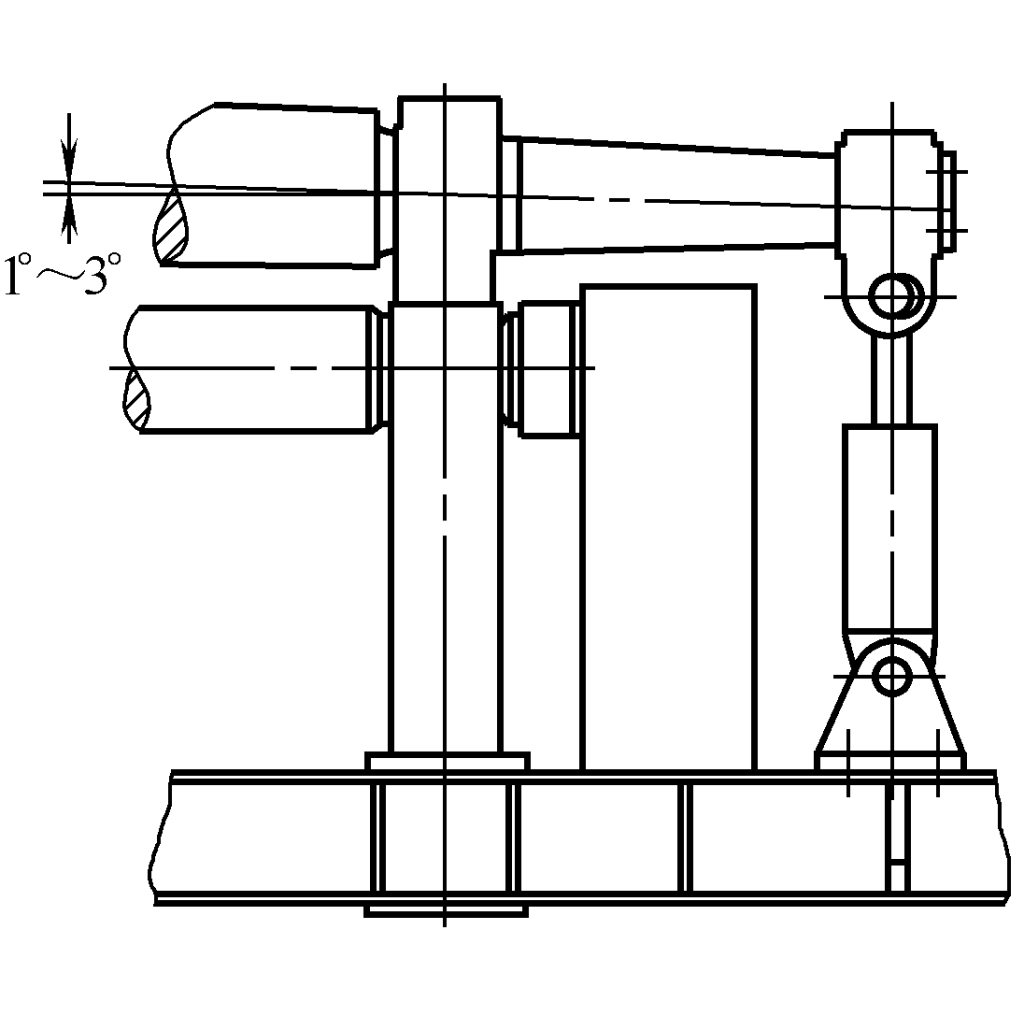
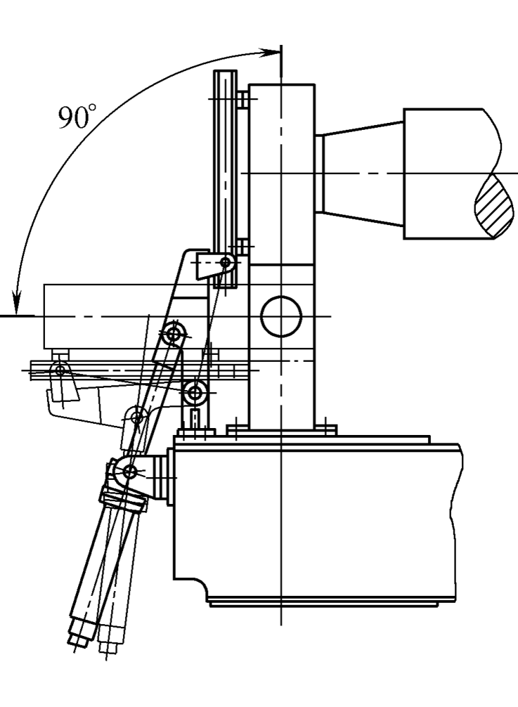
Figure 5 shows a disc spring balance mechanism. The lifting mechanism on the drive side and the bearing tipping mechanism on the discharge side are used to unload the cylindrical workpieces that have been roll-formed. The tipping mechanism can tilt the bearing body by 85°~90°, and the lifting mechanism can lift the upper working roller by 1°~3°.
1—Upper Roller
2—Lower Roller
3—Frame
4—Bearing Housing
5—Tie Rod
6—Support
7—Disc Spring
8—Adjusting Nut
9—Machine Base
For machines that roll wider plates, in order to improve the precision of the rolled workpieces and expand the range of the minimum roll diameter, the design pre-sets a uniform load compensation for the upper roll deflection at about 70% of the maximum force on the upper roll, thus making the roll body barrel-shaped (see Figure 6); some plate rolling machines also add a counter-pressure device at both ends of the upper roll to generate a certain reverse deflection in advance, to compensate for the deflection under working load. Large and wide plate rolling machines may have one or more sets of support rolls for the lower roll to increase the stiffness of the working roll.
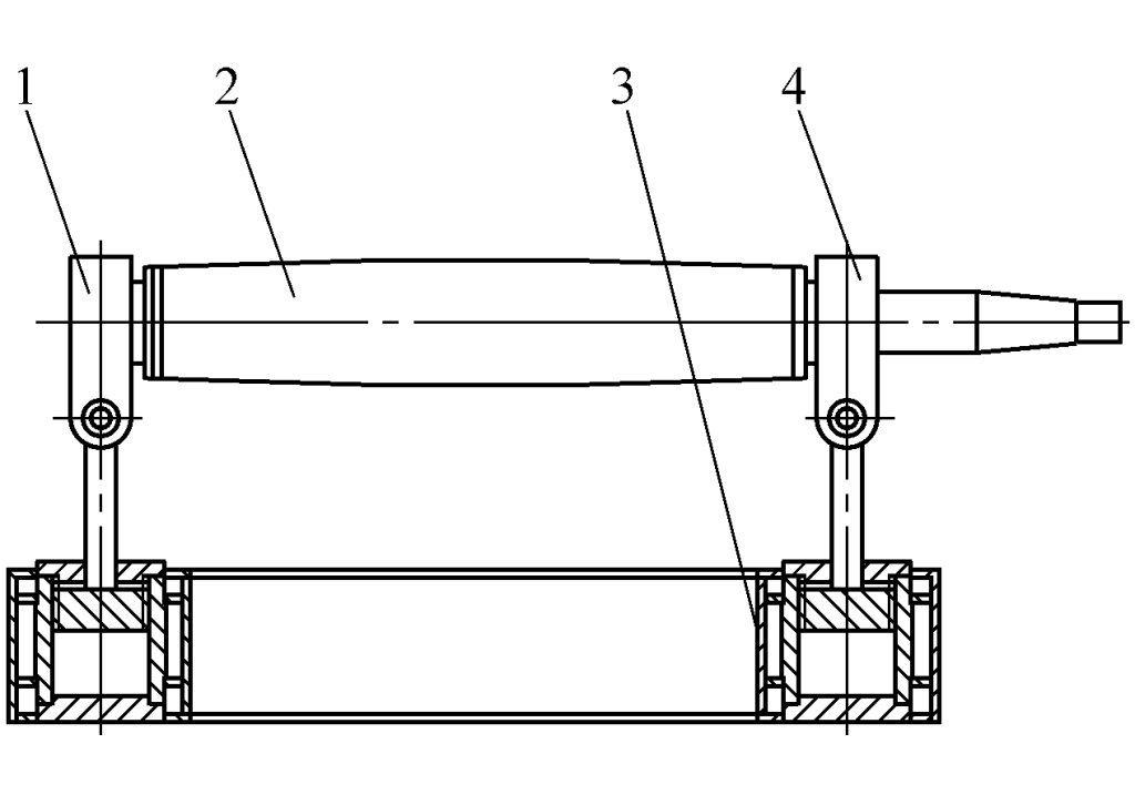
1—Tilting bearing housing
2—Upper roll
3—Base and main hydraulic cylinder
4—Right bearing housing
To make the generatrix of the workpiece parallel to the axis of the working roll during feeding, a centering groove can be opened on the body of the lower roll, or a material aligning device can be added.
Accessories for rolling conical workpieces can be installed at the tilting side of the upper roll end or on the frame. Since the development of a conical workpiece is a sector, rolling can be achieved by pressing the small end tightly against the friction block or friction wheel to reduce speed, realizing a faster line speed at the large end and slower at the small end, thus forming a cone.
Hot rolling and warm rolling can expand the working capacity of the plate rolling machine. When there are requirements for hot and warm rolling, the working roll material should generally be steel used for hot rolling work rolls, and bearings with good heat resistance, sufficient high-temperature load capacity, larger clearances should be selected, thermal insulation measures should be taken for bearings and other components, sealing parts should have good heat resistance, and the choice of grease should be reasonable.
The temperature range for hot rolling of steel plates is generally 850~1050℃, and the red brittleness temperature should be avoided; the temperature range for warm rolling is generally 400~600℃, and the blue brittleness temperature should be avoided, below the recrystallization temperature.
The control methods of plate rolling machines currently mainly include strong electric control, NC control, and CNC control. For strong electric control, the lifting and moving of its rollers generally use mechanical transmission, and the operation is manual; for NC control, the lifting and moving of its rollers generally use hydraulic transmission, the displacement is measured by high-precision sensors, controlled by PLC, automatically leveled, displayed on the screen, with leveling and positioning accuracy of ±0.2mm, and capable of simple data storage and editing functions.
For CNC control, the lifting and moving of its rollers are driven by hydraulics, the displacement is measured by high-precision sensors, controlled by PLC and industrial computers, displayed on a color monitor or touchscreen.
By entering parameters such as plate thickness, plate width, drum diameter, yield limit, correction factor (related to yield limit, etc.) from the keyboard or touchscreen, the computer can automatically calculate and optimize the number of rolling times, the lifting amount of each roller, displacement, the theoretical forming radius of each lift, and the load on each roller.
During pre-bending, it can output the theoretical minimum remaining straight edge value, and under screen prompts, arbitrarily choose the number of bends and the length of the pre-bent straight edge. When rolling cones, it can output the tilt amount of the upper roller. The operator can edit and store the calculated process parameters.
According to the force and stiffness requirements during plate rolling, this type of machine has a thicker upper roller and a thinner lower roller. Machines that roll wider plates are equipped with support rollers to improve the stiffness of the lower roller. This type of model has two lower rollers as the main drive rollers, and the upper roller as the passive roller. When equipped with a cone rolling device, it can roll conical parts. Due to its simple structure and convenient operation, it is widely used.
For this type of machine, the diameters of the upper and lower rollers are generally equal, and the diameter of the side roller is slightly thinner. Generally, the upper and lower work rollers are the main drive, and the side roller is passive; there are also machines where the lower roller and side roller are the drive, and the upper roller is passive. To achieve the lifting of the lower and side rollers, vertical and inclined sliding guide surfaces are set up on the frame, making the structure more complex.
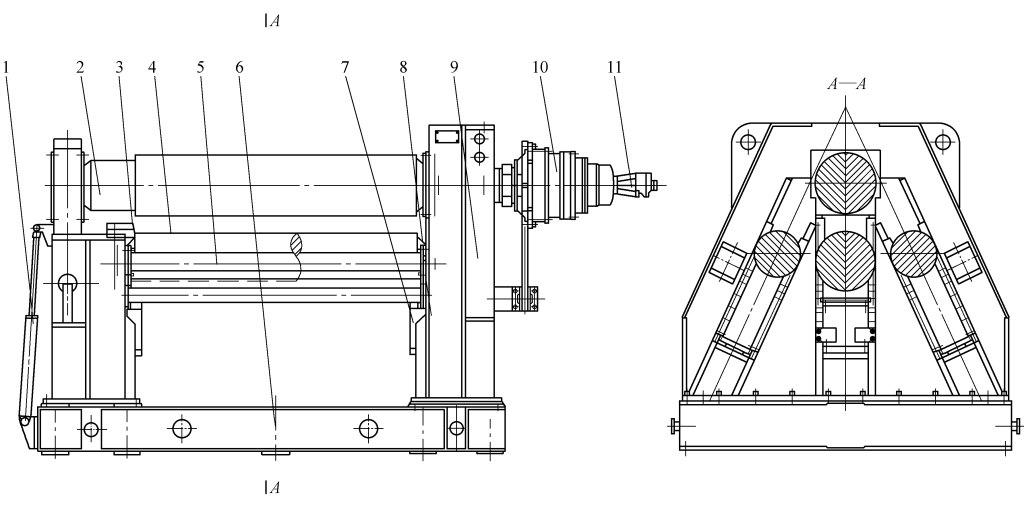
Figure 7 shows the W11XCNC—300/420×3200 horizontal down-adjustable three-roller plate bending machine designed and manufactured by Changzhi Steel & Iron (Group) Forging Machinery Company (Changzhi Forging Machine Tool Factory). The machine has an integral horizontal structure. The bearing body is connected to the piston rod of the main hydraulic cylinder mounted in the base, installed inside the left and right large frames.
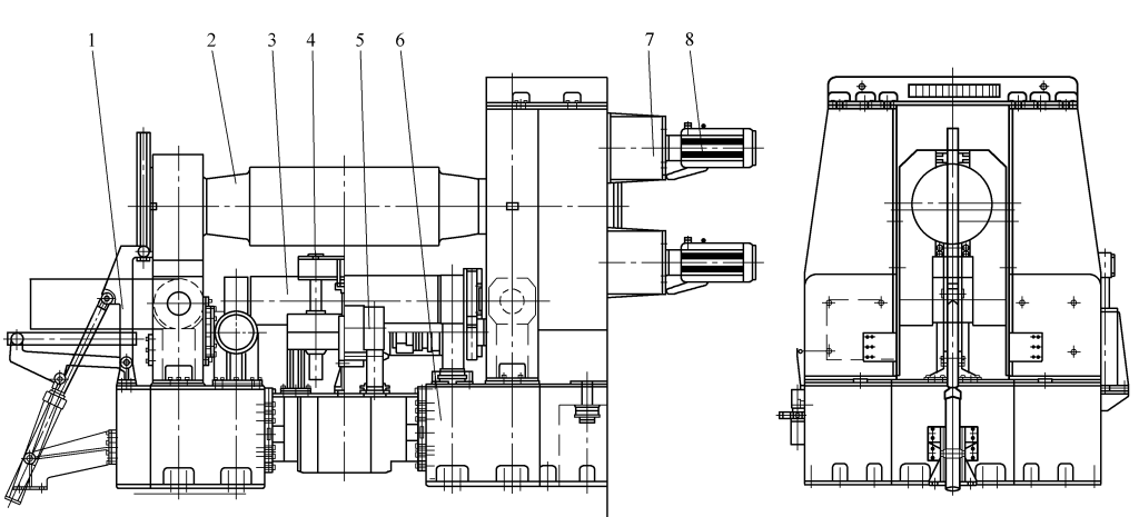
1—Tilting device
2—Upper roller part
3—Lower roller part
4—Material aligning device
5—Support roller part
6—Frame part
7—Planetary reducer
8—Electric motor
The lower roller and the left and right small frames that move horizontally are installed on the integral base. One end of the machine is equipped with a tipping mechanism, and the other end is equipped with a transmission system for three working rollers and a disc spring balance mechanism to facilitate the unloading of workpieces. The lifting of the upper roller (see Figure 6) and the horizontal movement of the lower roller (see Figure 8) are hydraulically driven.
a) Individual horizontal movement mechanism for the two lower rollers
b) Simultaneous horizontal movement mechanism for the two lower rollers
1—Lower roller hydraulic cylinder
2—T-shaped guide roller
3—Lower roller
4—Lower roller frame
There are two forms of horizontal movement for the lower roller, one is the simultaneous adjustment type (see Figure 8b): the other is the individual adjustment type (see Figure 8a). The former, due to its adjustable center distance, thus expands the processing capacity range of the machine; the latter, with both lower rollers installed on the same frame, allows the horizontal component forces to cancel each other out during rolling, resulting in a better force condition.
This machine is a three-roll full-drive with both upper and lower rollers. The rotational movement of the upper roller is driven by four electric motors or hydraulic motors through a planetary gear reducer. This transmission system is installed inside and outside of a steel plate welded box, and moves up and down along the guiding surface of the large frame together with the upper roller (see Figure 9).
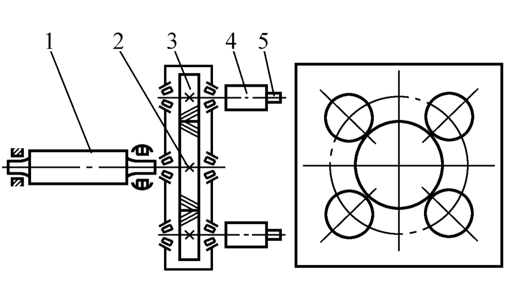
1—Upper roller
2—Large gear
3—Small gear
4—Planetary reducer
5—Electric motor
The rotary motion of the lower roller is driven by a hydraulic motor through a planetary gear reducer (for small models, it can also be directly driven by a low-speed high-torque hydraulic motor) as shown in Figure 10. This drive system is installed on the lower roller frame and moves horizontally with the lower roller moving mechanism. There are braking devices at the high-speed stage of both the upper and lower roller drive systems.
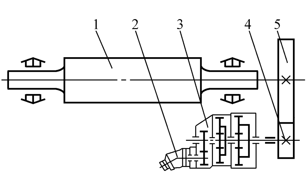
1—Lower roller
2—Motor
3—Planetary reducer
4—Small gear
5—Large gear
The three-roller full-drive rolling machine does not easily slip when rolling thin plates and small cylinder diameters, thus expanding the machine’s rolling range.
The main drive system rotates the two lower rollers through a multi-stage gear driven by an electric motor or hydraulic motor, and the upper roller is driven by chain transmission. To match the linear speed of the upper and lower rollers during the bending process, a safety clutch device is set up in the chain transmission mechanism.
In order to achieve precise positioning when pre-bending the plate, a braking device is set up in the high-speed stage of the transmission system. In addition, a transmission method where each of the three working rollers is driven independently by a motor reducer can also be adopted. Since all three working rollers are driven rollers, slipping is avoided when rolling small cylinder diameters and thin plates.
The arc lifting of the lower roller, the erection and tilting of the tilting bearing, and the flipping and resetting of the material handling device are powered by a hydraulic pump station and controlled through a valve group. The arc lifting mechanism of the lower roller is shown in Figure 11. The force of the hydraulic cylinder is increased through the turning arm, which can reduce the volume by 1/4 compared to the inclined downward-adjusting lifting hydraulic cylinder of the same specification. To ensure the accuracy of the machine, the turning arm is required to have sufficient strength and rigidity.
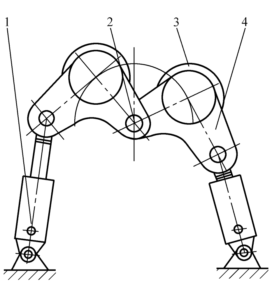
1—Hydraulic cylinder
2—Central axis
3—Lower roller
4—Swivel arm
The upper roller balancing mechanism adopts a top-pressing style, which ensures that the upper roller remains horizontal after the tilting side bearing housing falls. This mechanism consists of bearing bush, rolling bearing, adjusting screw, locking screw, etc. An accessory for winding conical workpieces is installed at the end of the upper roller on the tilting side.
The upper roller of the four-roller plate bending machine has a larger diameter, the lower roller diameter is generally slightly smaller than or equal to the upper roller, and the side rollers are smaller in diameter than the upper roller. The lower roller and side rollers are connected together through the bearing bodies and hydraulic cylinders at both ends, installed in two frames. Sliding guide grooves are set in the frame, driven by hydraulic cylinders or mechanical transmission to move the lower working roller and side working roller in a straight line in the guide grooves.
The lower part of the lower and side roller bearing housings adopts an arc-shaped self-aligning structure to accommodate the tilting and lifting of the working rollers. The main drive is generally driven by an electric motor or hydraulic motor through a planetary reducer or cylindrical gear reducer and a first-stage gear transmission (see figure 12). When driven by a hydraulic motor through a planetary reducer, a structure with the planetary reducer directly connected to the upper roller shaft end and equipped with a torque arm is usually adopted.
1—Tilting device
2—Upper roller
3—Cone rolling device
4—Lower roller
5—Side roller
6—Base
7—Lower roller hydraulic cylinder
8—Side roller hydraulic cylinder
9—Frame
10—Planetary reducer
11—Hydraulic motor
The frame consists of a closed frame and an open frame, made of steel plate welded components. In large and medium-sized four-roll bending machines, a support roller device is set in the middle of the lower roller to increase the support force of the lower roller when pre-bending the end of the plate and to compensate for the deflection deformation of the lower roller. The support roller is set on the hydraulic cylinder, and the adjustment of the support force is realized by hydraulic drive.
Figure 13 shows the working principle of the two-roll plate bending machine. During bending, the upper roll acts as a rotating punch, and the lower roll acts as a movable die. The depth of the upper roll pressing into the lower roll, that is, the deformation amount of the elastic layer, is the main process parameter determining the formed bending radius. The greater the pressing amount, the smaller the bending radius, but when the pressing amount reaches a certain value, the bending radius is no longer affected by the pressing amount and tends to stabilize.
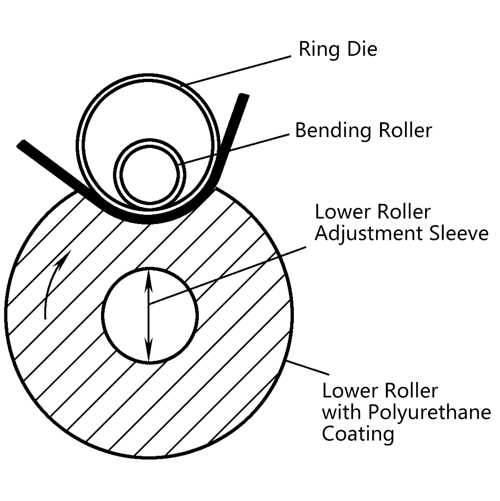
Within the “stable range”, the magnitude of the pressure applied to the roll is the main basis for determining the roll diameter, calculating the bending moment, and driving power. The elastic roll’s cladding material is generally polyurethane polymer.
The machine consists of a frame (left and right frames, base, connecting beams, etc.), upper crossbeam, upper working roll, upper support roll, lower working roll, lower support roll, upper roll lifting device, lubrication, hydraulic, electrical, and other parts. Generally, the two lower rolls are the driving rolls.
Figure 14 is the external view of the W11TNC-32×13500 closed (marine) three-roll plate bending machine. The two lower rolls of this machine are driven by electric motors or hydraulic motors through reducers from both ends. The machine has a simple structure, is easy to operate, and is the most widely used.
1—Main drive
2—Rack
3—Main hydraulic cylinder
4—Upper roller
5—Upper roller support
6—Lower roller
7—Lower roller support
The closed (marine) horizontal down-adjustable three-roller plate bending machine includes two structures: the two lower rollers can be adjusted independently (with adjustable center distance) and the two lower rollers can move horizontally at the same time (with fixed center distance).
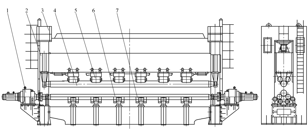
Figure 15 is a brand-new structure of closed horizontal down-adjustable plate bending machine developed by Changzhi Steel & Iron (Group) Forging Machinery Manufacturing Co., Ltd. (Changzhi Forging Machine Tool Factory), model W11TXNC-22000kN×16000mm. This machine can flexibly be used as a plate bending machine for bending and pre-bending arc or conical workpieces within a certain range; it can also be used as a press brake, bending steel plates with the help of bending molds.
1—Main drive system
2—Frame
3—Main hydraulic cylinder
4—Upper crossbeam
5—Upper work roll
6—Upper support roll
7—Lower work roll
8—Lower support roll
9—Lower roll lateral moving device
10—Lower crossbeam
11—Connecting beam
The machine is equipped with an adjustable hydraulic pre-bending device, which pushes the support roller with a wedge mechanism of different slopes through the hydraulic cylinder, causing the upper and lower working rollers to pre-bend and compensate for the deformation of the upper and lower beams. The longitudinal centerline positions of the two lower working rollers and their support rollers can be adjusted relatively, and the horizontal movement of the same working roller and the corresponding support roller is synchronized through the motor reducer and the screw lifting mechanism.
The vertical and inclined lifting of the upper working roller, support roller, and upper beam are driven by a main hydraulic cylinder installed on the upper part of the frame and two return hydraulic cylinders installed on the inside of the frame, both the main hydraulic cylinder and the return cylinders adopt a plunger cylinder structure. The two lower working rollers of the machine are the driving rollers, each driven by an independent hydraulic motor and a planetary reducer in both directions.
This machine is controlled by a microcomputer, and can set parameters such as upper roller pressure, lower roller horizontal position, and compensation amount of the upper and lower beams based on process parameters such as plate thickness, plate width, yield limit, and minimum rolling radius during rolling or bending, and has functions such as editing and storage.
The plate rolling flexible processing unit generally consists of a CNC plate rolling machine equipped with pre-treatment of plate material at the front and finished product conveying equipment at the rear, controlled by a control system composed of one or several computers, forming an automatic plate rolling processing unit. This unit integrates information flow and material flow into the CNC plate rolling machine system, capable of realizing small batch processing automation, making it an ideal high-precision, high-efficiency, and high-flexibility manufacturing system.
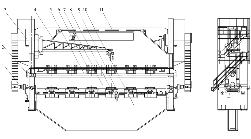
Figures 16 and 17 show the layout of the plate rolling flexible processing unit. The unit mainly consists of a plate storage platform, a loading robot arm loading workstation, a support device, and an unloading device. During plate rolling, the loading robot arm takes the material from the plate storage platform to the loading workstation, where the robot arm aligns the plate material and feeds it into the plate rolling machine.
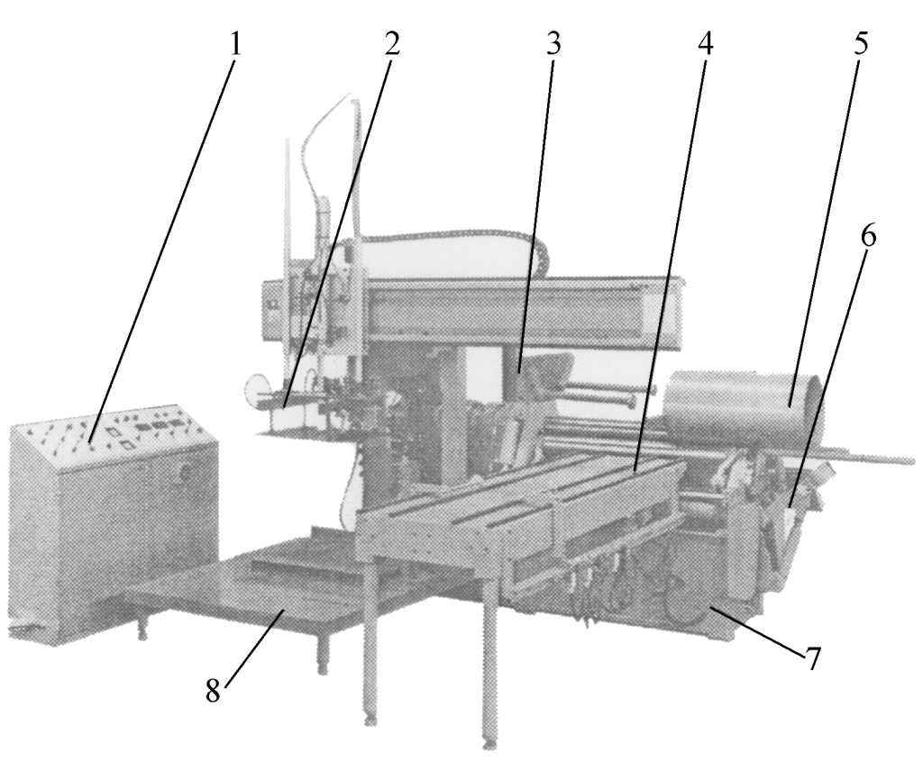
1—Electrical cabinet
2—Loading robot arm
3—Support device
4—Loading workbench
5—Workpiece
6—Unloading device
7—Plate rolling machine mainframe
8—Sheet metal stacking table
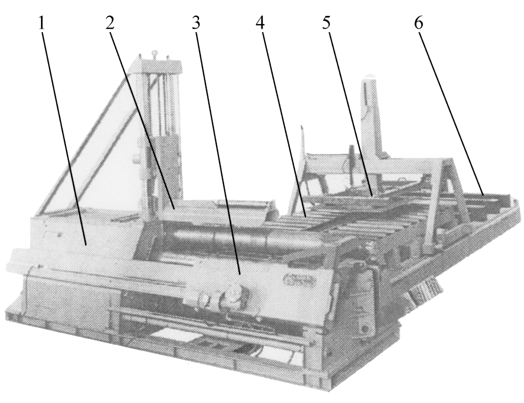
1—Plate rolling machine mainframe
2—Support device
3—Unloading device
4—Feeding roller conveyor
5—Loading robot
6—Sheet metal stacking table
During the rolling process, according to the shape, thickness, and cylinder diameter of the rolled workpiece, the robot arm always attaches to the inside or both inside and outside of the workpiece (fully automatic setting), and continuously supports and adheres to the workpiece as its curvature changes, until the workpiece is formed.
Subsequently, the bearing housing of the main machine’s tilting mechanism tilts down, the unloading robot arm pushes out the workpiece, the discharging robot arm grabs the workpiece and sends it to the finished product workbench, and the main machine and the robot arms at various positions return to their original positions, ready for the rolling of the next workpiece. In addition to the above configuration, some flexible plate rolling processing units can also be equipped with facilities for sheet metal alignment, cylindrical inspection, welding, etc.