I. Installation of Pneumatic Systems
1. Installation of Pipelines
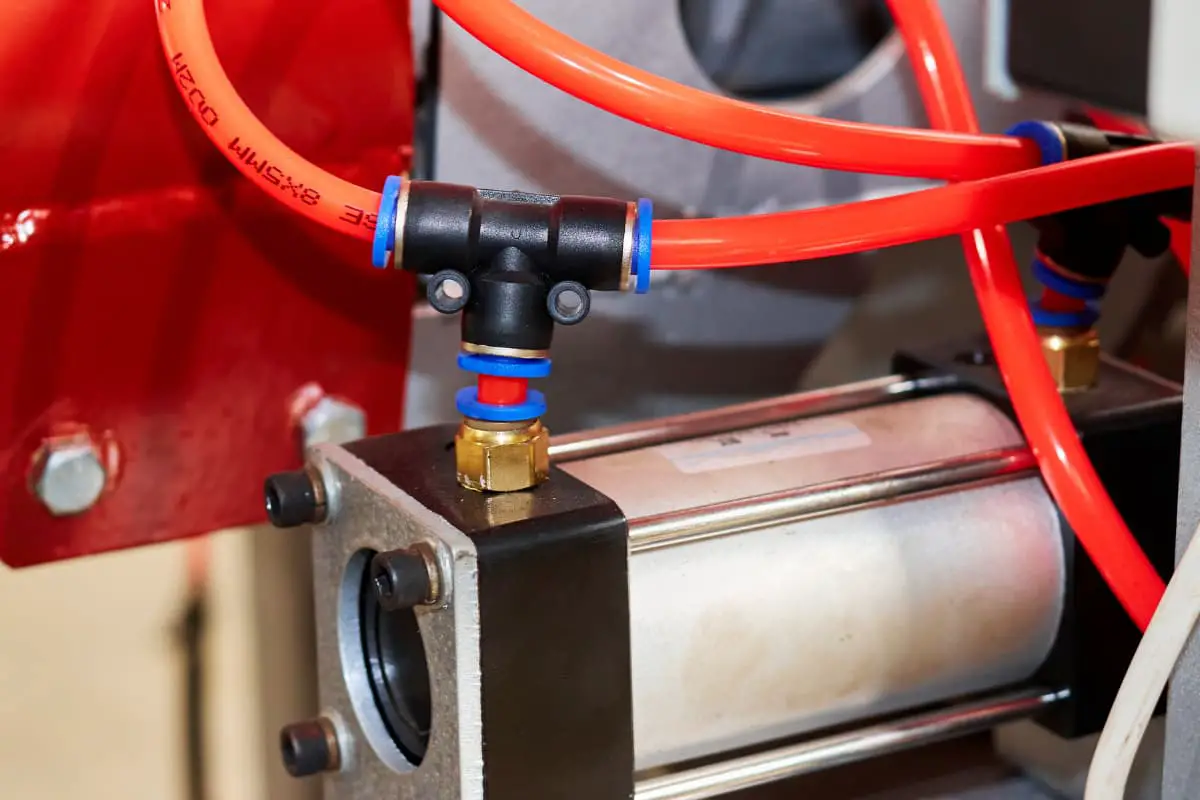
- Before installation, check if the inner wall of the pipeline is smooth, and remove rust and clean it.
- The pipeline supports should be firm and should not vibrate during operation.
- Tighten all joints, and the pipeline should not leak air.
- Pipeline welding should meet the specified standard conditions.
- When installing hoses, their length should have a certain margin; when bending, do not start bending from the end joint; when installing straight sections, do not stretch between the end joint and the hose; hoses should be installed as far away from heat sources as possible or install heat shields; any section of the pipeline system should be detachable; the inclination, bending radius, spacing, and slope of the pipeline installation should meet relevant regulations.
2. Installation of Components
- Before installation, clean the components and perform sealing tests if necessary.
- The direction of the arrows or markings on various valve bodies should match the direction of airflow.
- Logical components should be grouped and installed on the base plate according to the needs of the control circuit, and the air circuit should be led out on the base plate and connected with hoses.
- Do not install the sealing ring too tightly, especially the V-shaped sealing ring, as it has high resistance, so the tightness should be appropriate.
- The centerline of the moving cylinder and the centerline of the load force should be concentric, otherwise, it will cause lateral force, accelerating the wear of the sealing parts and bending the piston rod.
- Various automatic control instruments, automatic controllers, pressure relays, etc., should be calibrated before installation.
II. System Flushing and Pressure Testing
After the pipeline system is installed, use dry air with a pressure of 0.6MPa to blow out all impurities in the system. Use a white cloth to check, and if there are no impurities within 5 minutes, it is qualified. After blowing, disassemble and clean parts such as valve cores, filter elements, and pistons.
To check if the system’s sealing meets the standards, perform an air tightness test, generally keeping the system at 1.2 to 1.5 times the rated pressure for a period (e.g., 2 hours). Excluding errors caused by environmental temperature changes, the pressure change should not exceed the value specified in the technical documents. During the test, adjust the safety valve to the test pressure.
During the pressure test, it is best to use a step-by-step testing method and always pay attention to safety. If any abnormality is found in the system, stop the test immediately, find the cause, eliminate the fault, and then continue the test.
III. System Debugging
1. Preparations Before Debugging
- Familiarize yourself with the manual and other relevant technical materials to fully understand the system’s principles, structure, performance, and operation methods.
- Understand the actual position of the components that need adjustment on the equipment, the operation methods, and the direction of the adjustment knobs.
- Prepare debugging tools, instruments, and connect test pipelines as required by the manual.
2. No-Load Trial Operation
The no-load trial operation should not be less than 2 hours. Pay attention to changes in pressure, flow, and temperature. If any abnormal phenomena are found, stop the machine immediately for inspection, and continue operation only after the fault is eliminated.
3. Load Trial Operation
The load trial operation should be carried out in stages, and the operation should not be less than 2 hours. Pay attention to the temperature rise of the friction parts, measure the relevant data separately, and record it in the test run log.
IV. Use and Maintenance of the Pneumatic System
1. Precautions During Use
- Before and after driving, release the condensate in the system and check whether all adjustment knobs are in the correct position before driving. Ensure the positions of the travel valve, travel switch, and stopper are correct and secure. Wipe the mating surfaces of exposed parts such as guide rails and piston rods.
- Always pay attention to the cleanliness of the compressed air. Regularly clean the filter element of the water separator and regularly add oil to the oil mist device.
- When the equipment is not used for a long time, loosen all knobs to prevent spring failure from affecting component performance.
- Familiarize yourself with the operating characteristics of the component control mechanisms to prevent accidents caused by incorrect adjustments. Pay attention to the relationship between the rotation direction of each component’s adjustment knob and changes in pressure and flow rate.
2. Pollution and Prevention of Compressed Air
The quality of compressed air greatly affects the performance of the pneumatic system. If contaminated, it can cause pipeline and component corrosion, seal deformation, and nozzle blockage, preventing the system from functioning properly. The main sources of compressed air pollution are moisture, oil, and dust.
(1) Moisture
The air compressor inhales moist air containing water. After compression, the pressure increases, and when it cools again, condensate precipitates, infiltrating the compressed air and causing pipeline and component corrosion, affecting their performance.
Methods to prevent condensate from infiltrating compressed air include:
- Timely discharge of condensate accumulated in the system’s drain valves.
- Regularly check whether the automatic drain and dryer are functioning properly.
- Regularly clean the internal components of the water separator and automatic drain.
(2) Oil
This refers to used lubricating oil that has deteriorated due to heat. Some of the lubricating oil used by the air compressor mixes with the compressed air in a mist form, vaporizes when heated, and enters the system with the compressed air, causing seal deformation, air leakage, increased friction resistance, poor valve and actuator performance, and environmental pollution.
Methods to remove oil from compressed air include: separating larger oil particles from the air using oil-water separators and water separators, and discharging them through the equipment’s drain valve. Smaller oil particles can be removed through adsorption by activated carbon.
(3) Dust
Dust in the atmosphere, rust particles inside pipelines, and debris from sealing materials can infiltrate compressed air, causing moving parts to jam, malfunction, block nozzles, accelerate component wear, reduce service life, and lead to failures, severely affecting system performance.
Main methods to prevent dust from infiltrating compressed air include:
- Regularly clean the pre-filter in front of the air compressor.
- Regularly clean the filter element of the water separator.
- Timely replacement of filter elements.
3. Daily Maintenance of the Pneumatic System
Daily maintenance of the pneumatic system mainly involves managing condensate and system lubrication.
(1) Management of Condensate
Condensate discharge involves the entire pneumatic system, from the air compressor, aftercooler, air tank, pipeline system to various air filters, dryers, and automatic drains. At the end of operations, discharge condensate from all locations to prevent freezing due to nighttime temperatures dropping below 0°C.
Since the temperature inside the pipeline drops at night, further precipitating condensate, discharge condensate from the pneumatic device before daily operation. Check whether the automatic drain is functioning properly, and ensure the water cup does not contain excessive water.
(2) Management of System Lubrication
In the pneumatic system, all surfaces with relative motion, from control components to actuators, require lubrication. Improper lubrication can increase friction resistance, cause poor component performance, or lead to system leakage due to wear on sealing surfaces.
The properties of lubricating oil will directly affect the lubrication effect. Generally, high-viscosity lubricating oil is used in high-temperature environments, and low-viscosity lubricating oil is used in low-temperature environments. If the temperature is particularly low, a heater can be installed in the oil cup to overcome the difficulty of fogging.
The oil supply amount varies with the shape, motion state, and load size of the lubrication part. The oil supply amount is always greater than the actual required amount. Pay attention to whether the oil mist generator is working properly. If the oil amount does not decrease, adjust the oil drip amount in time. If the adjustment is ineffective, the oil mist generator should be repaired or replaced.
4. Regular maintenance of the pneumatic system
The interval for regular maintenance is usually three months. The main contents are:
(1) Identify the leakage parts of the system and try to solve them.
(2) By checking the exhaust port of the directional control valve, determine whether the amount of lubricating oil is appropriate and whether there is condensate in the air.
If the lubrication is poor, consider whether the specifications of the oil mist generator are appropriate, whether the installation position is correct, and whether the oil drip amount is normal. If a large amount of condensate is discharged, consider whether the installation position of the filter is appropriate, whether the condensate discharge device is suitable, and whether the condensate is completely discharged.
If there is still a small amount of leakage when the exhaust port of the directional control valve is closed, it is often the initial stage of component damage. After inspection, worn parts can be replaced to prevent malfunction.
(3) Check whether the safety valve and emergency safety switch are operating reliably. During regular maintenance, the reliability of their operation must be confirmed to ensure equipment and personal safety.
(4) Observe whether the operation of the directional valve is reliable. Determine whether there are impurities in the matching parts of the iron core and armature based on whether the sound is abnormal during switching. Check whether the valve core is worn and whether the sealing parts are aging.
(5) Repeatedly switch the directional valve and observe the cylinder operation to determine whether the seal on the piston is good. Check the exposed part of the piston rod to determine whether there is leakage at the matching part of the front cover.
The results of the above inspections and repairs should be recorded for use in troubleshooting and major repairs.
The overhaul interval of the pneumatic system is one year or several years. The main content is to check the performance and life of each component and part of the system, and to repair or replace components in parts that usually fail, eliminating all possible failure factors within the repair interval.

