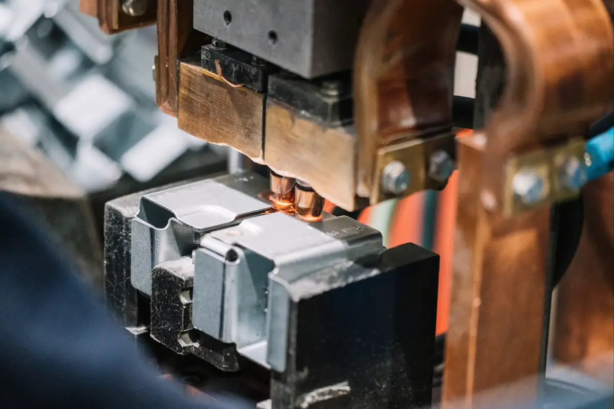
To meet the requirements of mass production of forgings, it is advisable to use special forging processes such as precision die forging, radial forging, rolling and expanding, isothermal die forging, powder forging, liquid die forging, multidirectional die forging, crankshaft upsetting, etc.
I. Precision die forging
The forging method that achieves precision-grade tolerances and allowances as specified by GB/T12362-2003 is called precision die forging. There are many precision die forging methods, and this section refers to precision die forging using common forging equipment such as hammers, friction presses, and crank presses.
1. Classification, process, and advantages of precision die forging
Table 1 Classification, process, and advantages of precision die forging
| Item | Description |
| Classified by heating temperature | There are three types of precision die forging methods currently used: high-temperature precision die forging, medium-temperature precision die forging, and room-temperature precision die forging 1) High-temperature precision die forging (referred to as precision forging or fine forging). The blank is heated in a controlled atmosphere to prevent severe oxidation and decarburization of the blank surface. A low-oxidation open flame furnace is usually used. The depth of the surface oxidation layer of the blank is 0.011 to 0.013mm, with good results 2) Medium-temperature precision die forging (referred to as warm forging). Medium-temperature precision die forging is a method of heating within a temperature range that does not produce strong oxidation and then performing die forging 3) Room-temperature precision die forging (referred to as cold die forging). Heating of the blank before forging is eliminated, solving the oxidation issue, but the challenge is to ensure good plasticity and low deformation resistance required for die forging. For this, some pre-forging softening and surface treatments must be adopted |
| Process | The surface of precision forgings should not have or only allow a small amount of scale, therefore, efforts must be made to prevent and eliminate scale throughout the entire process. The general process is as follows Cutting → Cleaning the billet → Heating → Making the billet → Cleaning the blank → Heating → Rough forging → Trimming → Cleaning the rough forging → Heating → Precision die forging → Normalizing (or annealing) → Cleaning the forging → Trimming → Straightening (or cold finishing) → Trimming |
| Process advantages | 1) The forging has higher dimensional accuracy and lower surface roughness, requiring little or no machining, with the tolerance margin for general precision forgings being about 1/3 of that for ordinary forgings, and a surface roughness Ra of 2.5~3.2μm, see Table 2 2) Saves metal, improves productivity 3) Has good metal structure and flow lines, improving the mechanical properties of the parts 4) Low production cost of parts |
Table 2 Comparison of surface roughness and precision between precision die forgings and ordinary die forgings
| Processing method | Surface roughness Ra/μm | Accuracy grade |
| Die forging | 10.0~12.5 | 8~12 |
| Precision die forging | 2.5~3.2 | 6~10 |
2. Comparison of technical and economic indicators between precision die forgings and ordinary die forgings
Table 3 Comparison of technical and economic indicators between precision die forgings and ordinary die forgings
| Part name | Material utilization rate | Productivity | Mechanical properties | |
| Ordinary | Precision forging | |||
| Planetary bevel gear | 37% | 80% | Increase by 2.3 times | Increase |
| Drive gear (spur cylindrical gear) | — | Increase by 1 time | Increase by 10 times | Increase |
| Rolling mill roller way bevel gear | 43.30% | 64% | Increase by 12 times | Improve |
| Steam turbine blades | — | Save 60% | Reduce machining by 40% | — |
| BT-100 type steam turbine 16th stage working blades | 29% | 46% | Reduce machining by 30% | — |
| Jack cover | 53% | 80% | Reduce machining by 50% | — |
3. Main technical measures of precision die forging
To obtain high-precision forgings, measures must be taken in various aspects such as blanking, heating, molds, equipment, and process factors, and strict inspections must be conducted between each process (see Table 4).
Table 4 Main Technical Measures for Precision Die Forging
| Technical Measures | Content |
| Precision Blanking | Precision die forging has high requirements for the geometric accuracy, cross-sectional quality, and weight tolerance of the billet, so it is necessary to use precision blanking methods. Common precision blanking methods are shown in Table 5. |
| Minimal Oxidation Heating | The surface of precision forged parts should have no or only a small amount of scale, and the thickness of the decarburized layer should be controlled, therefore, minimal oxidation heating methods must be used. Common methods include coating the billet surface with a protective film, using rapid electrical heating or protective gas electrical heating, and using low oxidation heating furnaces with fuel oil or gas. The heating temperature of the billet should be reduced as much as possible, and cold or warm forging should be performed. |
| High Precision Molds | The tolerance allowance for precision forged parts should be determined according to the precision level of GB/T12362-2003. To achieve the required precision level dimensional tolerances and surface roughness, high precision molds must be used. Precision die forging often uses modular molds, which should have reliable guiding and ejecting devices. The mold precision should be 1 to 2 grades higher than the forging precision. The surface roughness of the mold cavity, Ra, should not be less than 0.8um. Comparison of surface roughness and precision grades between precision forging and ordinary forging is shown in Table 1 |
| Reasonably select and control process factors | It is necessary to reasonably select and strictly control process factors such as mold temperature, forging temperature, and lubrication conditions Common lubricants for precision forging are shown in Table 6 |
Table 5 Main methods of precision blanking
| Blanking methods | Basic principles |
| Sawing | Cutting metal using bow saws, circular saws, band saws, etc. |
| Turning | Using a lathe to cut metal |
| Self-constrained shearing | Axial deformation during shearing is constrained, changing the stress state of the metal, allowing it to separate through plastic deformation without the occurrence of shear cracks |
| Radial clamping shearing | The bar is sheared under radial clamping, with the metal in the shear zone under triaxial stress |
| Axial compression shearing | Axial pressure is applied to both ends of the bar, putting the metal in the shear zone under triaxial compression |
| Progressive shearing | Using the eccentric rotation of the moving and stationary shears to shear from around the bar |
| Special machine shearing | Using advanced precision bar cutting machines, the cut defective material is of good quality and the production efficiency is high. |
Table 6 Common lubricants for precision die forging
| Forging temperature | Method of use | Lubricant |
| Warm forging (<800℃) | Defective material is pre-treated with phosphating | Molybdenum disulfide, graphite, aqueous graphite |
| Hot forging | Sprayed on the surface of the forging and the mold | Graphite oil, aqueous graphite, glass lubricant, molybdenum disulfide |
II. Radial forging
1. The essence of the radial forging process, deformation characteristics, and advantages
Table 7 The essence of radial forging process, deformation characteristics, and advantages
| Process essence | Radial forging (also known as rotary forging) involves using two or more hammers distributed around the cross-section of the blank to strike the blank at high speed and in synchronous symmetry. During the forging process, there is both relative axial movement and rotational movement between the blank and the hammers. |
| Deformation characteristics | 1) During radial forging, each forging deformation is very small, the deformation zone is small, and the volume of metal moved is also very small, thus greatly reducing the required deformation force and work, but the number of forging strikes per unit time is high (referred to as “pulsating loading”) and there are many feedings. 2) Pulsating loading reduces friction both inside and outside the metal, making deformation more uniform, easier to penetrate internally, and beneficial for improving the plasticity of the metal, increasing the plasticity of low-plasticity alloys by 2.5 to 3 times. 3) During radial forging, three methods can be used: hot forging, warm forging, and cold forging. The initial forging temperature for hot forging is 100 to 200°C lower than general die forging, typically between 900 and 1000°C. The initial forging temperature for warm forging is between 200 and 700°C. 4) Radial forging is commonly used to manufacture various stepped shafts, with cross-sections that can be circular, square, and polygonal (as shown in the figure), complex inner hole shapes or hollow shafts with small inner diameters and long lengths (as shown in figure b), and can be used in assembly processes (as shown in figure c). When forging hollow parts, a mandrel can be inserted or not, mainly depending on the wall thickness of the tube blank. Mandrel-free forging is used when the ratio of wall thickness to diameter of the tube blank is large; if the tube blank wall is thin and without a mandrel, with a large amount of pressing, folding is easy to form.  Typical parts of radial forging |
| Advantages | 1) Requires less deformation force, high tool life: Generally, the number of strikes for a radial forging shaft machine is 1800~3200 times/min, thus it has a higher production rate. 2) High precision of forgings, thermal forging dimensional accuracy can reach level 6~7, surface roughness Ra is 3.2~6.3μm; cold forging dimensional accuracy can reach level 2~ 4, surface roughness Ra is 0.4~0.8μm 3) Uniform deformation, can forge low plasticity high strength alloy steel 4) Can forge various stepped shafts, whose cross-sections can be circular, square, or polygonal, and can also forge hollow shaft parts with complex inner hole shapes. |
2. Classification and working principle of radial forging equipment
Table 8 Classification and working principle of radial forging equipment
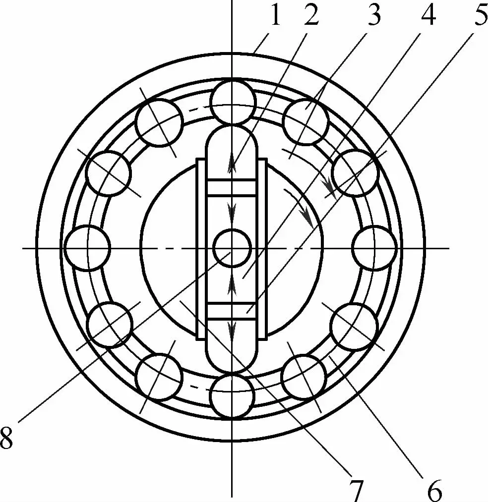 Figure 1 Schematic diagram of the roller rotary forging machine 1—Outer ring 2—Slider 3—Ball 4—Hammerhead 5—Adjustment shim 6—Clamp ring 7—Main shaft 8—Blank | 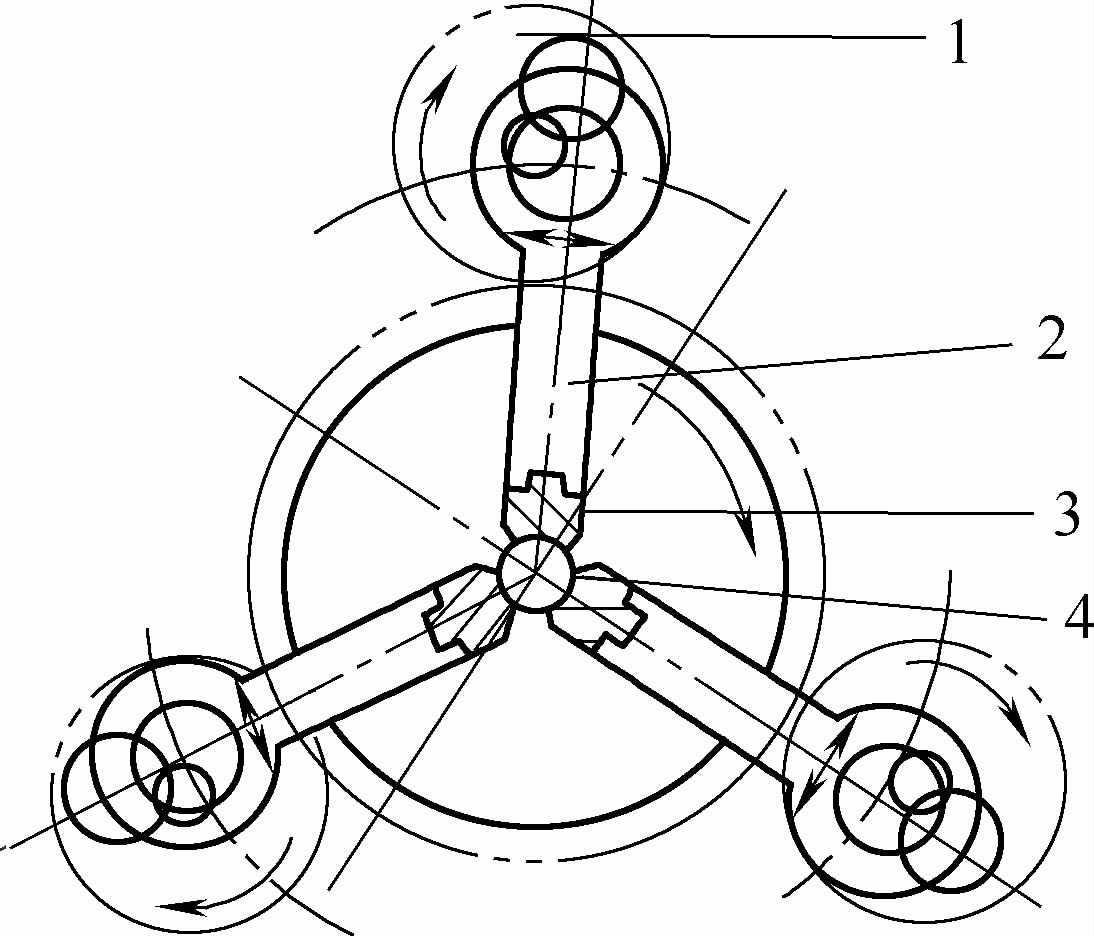 Figure 2 Schematic diagram of the crank radial forging machine 1—Eccentric shaft 2—Connecting rod 3—Hammerhead 4—Blank |
| Classification | Working principle |
| Roller rotary forging machine | See Figure 1 for the schematic diagram. The hammerhead 4 and slider 2 are mounted on the guide rails of the main shaft 7 and rotate with the main shaft. Evenly distributed around the circumference of the main shaft are an even number of balls 3, which are restricted in a certain position by the clamp ring 6 and fitted inside the outer ring 1. When the main shaft rotates causing the slider to be acted upon by the roller, the slider and hammerhead move towards the center of the main shaft, the hammerhead closes and forges the blank 8. As the main shaft rotates, the slider and roller disengage, and under the action of centrifugal force, the slider and hammerhead move away from the center, repeating the process to achieve repeated striking. When the hammerhead opens, the blank is fed axially to form the forging. See Table 9 for its technical parameters. |
| Crank radial forging machine | See Figure 2 for the schematic diagram. The connecting rod 2, driven by the eccentric shaft 1, drives three hammerheads 3 to reciprocate, striking the blank 4. The hammerhead can perform radial feed movement to change the forging stroke and forge stepped shafts with varying cross-sections. The radial feed of the hammerhead and the axial feed of the blank are controlled by an electrical hydraulic system. See Table 10 for its technical parameters. |
Table 9 Main Technical Parameters of Radial Roller Forging Machine
| Parameters | Model D21-4.2 | Model D21-7.3 | Model D21-17.5 | Model D24-30 |
| Maximum Diameter of Defective Material/mm | 4.2 | 7.3 | 17.5 | 30 |
| Minimum Diameter After Forging/mm | 1.1 | 4.1 | 7 | 6 |
| Spindle Speed/(r/min) | 1200 | 900 | 600 | 270 |
| Feeding Speed/(m/min) | 3.5 | 2 | — | 1.44 |
| Motor power/kW | 1.0 | 1.7 | 1.7 | 10 |
| Dimensions (Length × Width × Height)/mm | 1040×730×1300 | 780×760×1300 | 780×760×1300 | 1560×1360×1230 |
| Machine weight/kg | 300 | 465 | 635 | 1478 |
Note: D24-30 is a radial forging machine for pipe material.
Table 10 Main technical parameters of crank-type radial forging machine
| Parameters | D61-80 | D61-80A | D63-80 |
| Number of hammers/pcs | 3 | 3 | 3 |
| Striking force/kN | 1000 | 1000 | 1000 |
| Number of strikes/(times/min) | 600 | 600~800 | 600 |
| Maximum diameter of forgeable workpiece/mm | 80 | 80 | 80 |
| Maximum length of forgeable workpiece/mm | 1000 | 1000 | 1000 |
| Maximum compression amount on diameter/mm | 14 | — | 14 |
| Hammer head adjustment amount/mm | 36 | 40 | 36 |
| Main motor power/kW | 28 | 40 | 28 |
| Dimensions (Length × Width × Height)/mm | 3000×3000×4500 | 2000×1700×3600 | 3000×3000×6500 |
| Parameters | JD-135 | DA65-125 | DA65-85 |
| Number of hammer heads/pcs | 3 | 2 | 4 |
| Striking force/kN | 1000 | 2500 | 1200 |
| Number of strikes/(times/min) | 500 | 600 | 600~800 |
| Maximum diameter of forgeable workpiece/mm | 135 | 125 | 85 |
| Maximum length of forgeable workpiece/mm | 1100 | 1300 | 700 |
| Maximum compression amount on diameter/mm | 18 | — | — |
| Hammer head adjustment amount/mm | 90 | 50 | 45 |
| Main motor power/kW | 28 | 55 | 55 |
| Dimensions (Length × Width × Height)/mm | 1920×1890×4800 | 5700×3100×1600 | 9000×9000×2000 |
Note: Model DA65 is a horizontal radial forging machine.
3. Radial forging process example
Table 11 Radial forging process example
| Serial number | Name | Craft process |
| 1 | Solid step shaft | Forge the main spindle of a conventional lathe (see Figure 1), swage out a Φ205mm head from a Φ115mm×730mm steel billet on a 1t free forging hammer, then clamp the head on a radial forging machine to precisely forge the rod part. The work cycle is shown in Figure 1, where work cycle 1 uses a small reduction amount (2~4mm) for push forging and removes oxide scale. From step 5, first forge the Φ115mm billet to Φ96mm, then progressively forge to Φ85mm, Φ80mm. Compared to the original free forging process, each forging saves 11.4kg of steel.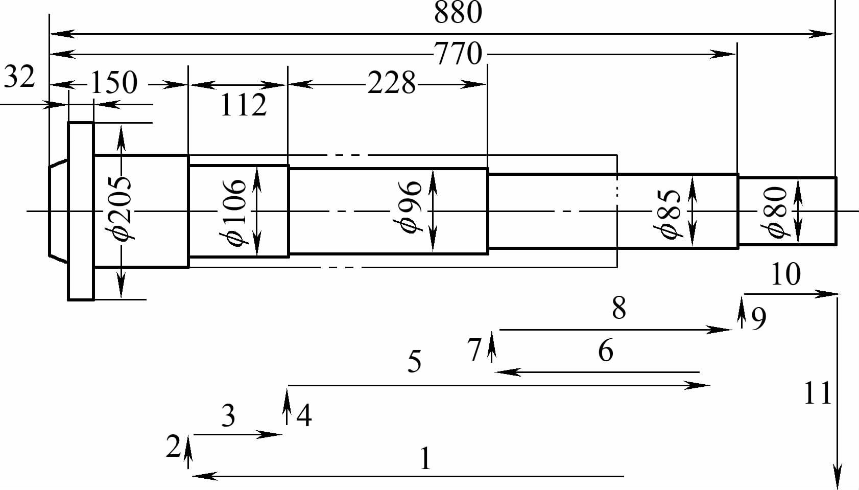 Figure 1 Schematic diagram of the conventional lathe spindle and work cycle |
| 2 | Hollow transition shaft | Both its external shape and internal hole have steps, with diameters arranged from largest to smallest. The blank is a Φ135mm×27mm 40CrNiMoA seamless steel tube. In the work cycle, step 4 forges to Φ105mm, then step 5 immediately demolds (see Figure 2), step 6 the chuck rises a section, step 7 re-enters the mold to forge the lower half of Φ105mm, filling the Φ35mm inner hole. Due to the large reduction in the last segment of the forging, two forging processes are used, the first forges to Φ105mm, with the blank already clamping the mandrel; the second forges to Φ80mm, forcing the blank to slide down on the mandrel. 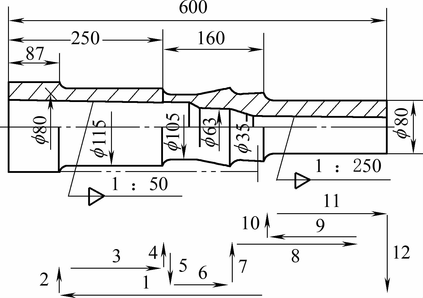 Figure 2 Schematic diagram of the hollow transition shaft and work cycle |
III. Rolling and expanding
1. The essence, characteristics, and application of the rolling and expanding process
Table 12 Rolling Expansion Hole Technology Essence, Characteristics and Product Applications
| Project | Description |
| Technology Essence | 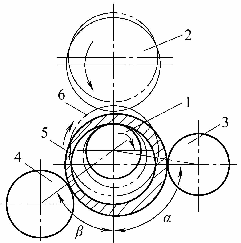 Figure 1 Rolling Expansion Working Principle 1—Driven roller 2—Driving roller 3—Guide roller 4—Control roller 5—Workpiece 6—Blank Rolling expansion is a process on a specialized expansion machine that thins the wall thickness of a ring-shaped blank, increasing both the inner and outer diameters to obtain the required ring-shaped parts. There are four types of rollers on the expansion machine: driving roller, driven roller, guide roller, and control roller. The working process is shown in Figure 1. The heated ring-shaped blank is placed on the driven roller 1, while the driving roller 2 rotates the ring blank and simultaneously moves radially under hydraulic pressure, causing the blank to be compressed and stretched, reducing the wall thickness and increasing both the inner and outer diameters. The guide roller 3 always rests on the workpiece and moves outward as the diameter of the workpiece increases. Its function is to stabilize the rotation of the workpiece and shape it. When the outer diameter of the workpiece reaches the required size, the workpiece contacts the control roller 4, sending a signal to retract the driving roller, ending the expansion. The electric motor only drives the driving roller to rotate, while the other rollers rotate by friction. According to production experience, the angle α between the guide roller and the main axis should be greater than 65°, and the angle β between the control roller and the main axis should be greater than 55°. |
| Characteristics | 1) High forging precision, diameter limit deviation of ±1mm; improves the structure and properties of the metal, resulting in good product quality. 2) High material utilization rate, high productivity 3) Low investment, good working conditions |
| Product application | Rolling expansion is suitable for producing ring parts or blanks of various shapes, sizes, and materials. Currently, the diameter of rolled rings ranges from Φ20 to Φ10000mm, height from 10 to 4000mm, wall thickness from 2 to 48mm, and the weight of the rings from 0.1 to 82000kg. The materials of the rings are usually carbon steel, alloy steel, aluminum alloy, copper alloy, titanium alloy, cobalt alloy, nickel-based alloy, and bimetal, etc. Common rolled ring products include bearing rings, gear rings, train wheels and rims, gas turbine rings, collector rings, etc. The largest rolled ring is a nuclear reactor vessel ring with a diameter of Φ10000mm and a height of 4000mm. A typical rolled ring product cross-section shape is shown in Figure 2.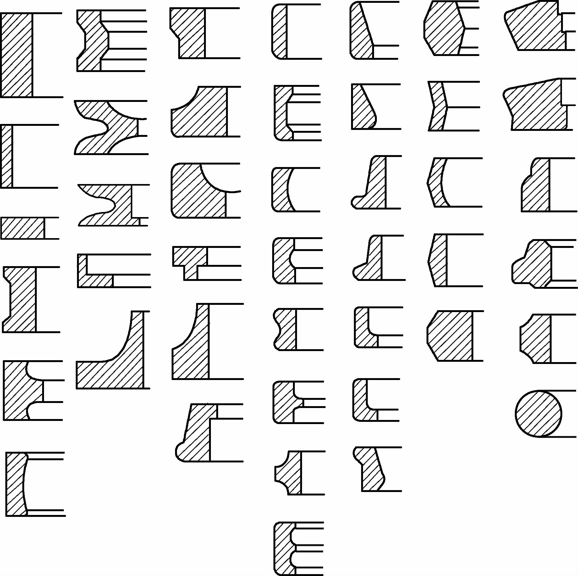 Figure 2 Cross-sectional shape of the rolled expansion product |
2. Rolling expansion process
Table 13 Rolling expansion process
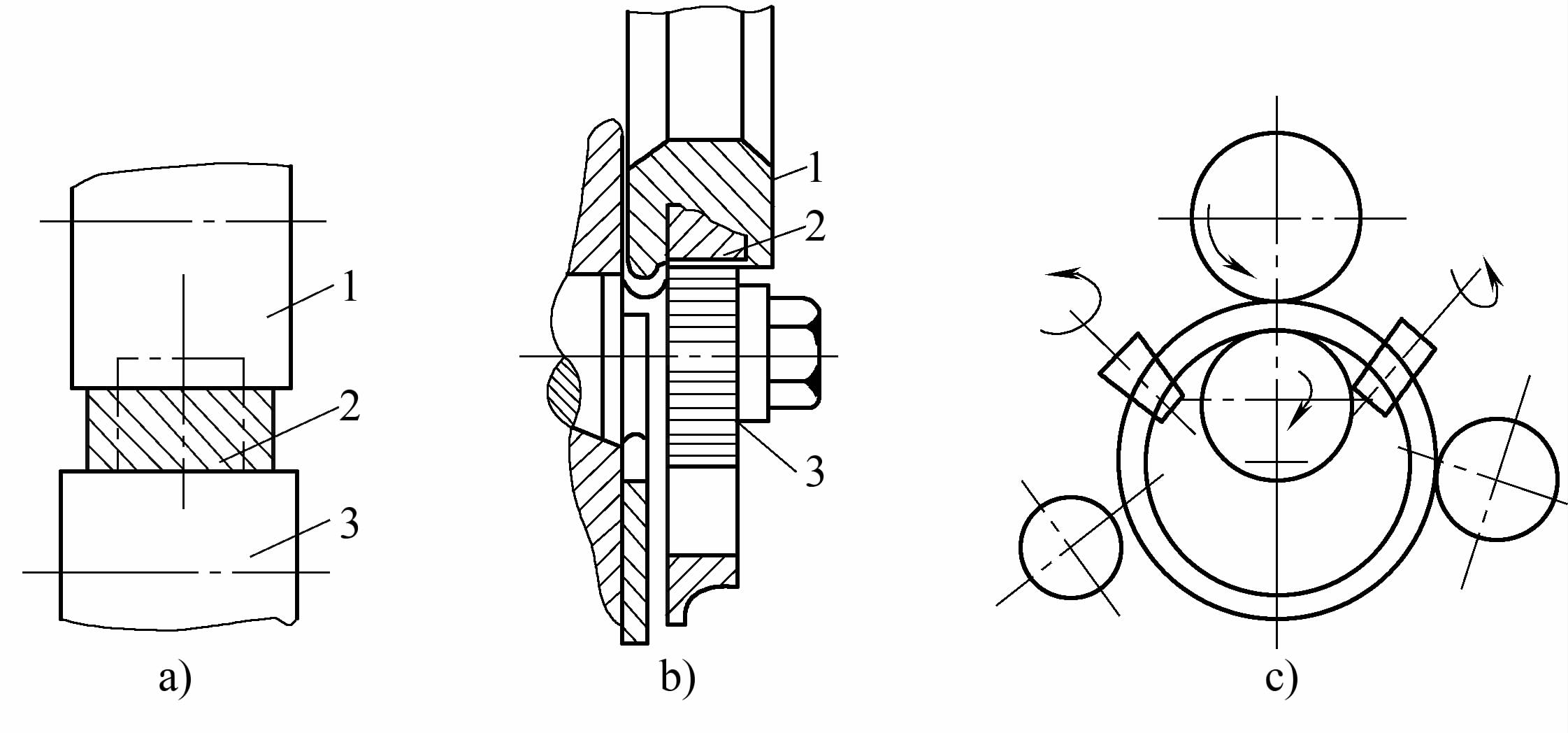 Roll groove types a) Open expansion b) Closed expansion c) Semi-open expansion 1—Drive roll 2—Workpiece 3—Driven roll | ||
| Content | Description | |
| Expanding roll groove type | Open type | The open type expanding roll is a flat roll, mainly used for rolling rectangular section rings, as shown in figure a. To avoid widening caused by uneven deformation, two pairs of freely rotating conical rolls can be added to the expander, as shown in figure c. |
| Closed type | Closed type expanding is used for expanding rings with irregular cross-sections, as shown in figure b. | |
| Determination of billet size | If the height remains unchanged before and after expanding, the forging ratio K before and after expanding is calculated by the following formula K = (D 0 – d 0 ) / (D 1 – d 1 ) Where in the formula D 0 , d 0 – outer and inner diameters of the ring blank D 1 , d 1 – outer and inner diameters of the forging For open-type grooves, take K=1.3~1.6; for closed-type grooves, take K=1.25~1.35. For larger workpieces, take a higher K value Based on the K value, determine the size of the blank according to the principle of equal volume before and after boring, considering the burn-off | |
3. Boring machine type and main technical parameters
Table 14 Types of boring machines
| Type | Main features |
| Vertical boring machine (ring rolling machine) | Specifications generally less than 400mm. The machine body is vertically placed but slightly tilted backward to facilitate loading and unloading and to increase the stability during the rolling process. |
| Horizontal Expanding Machine (Ring Rolling Machine) | Specifications size greater than 400mm. The machine body is set horizontally, with 2 to 4 guide rollers, and equipped with upper and lower face rolling rollers, automatic control of rolling expansion size or with digital display, equipped with mechanized loading and unloading device. Complex structure, good workpiece quality, capable of rolling expansion of various cross-sectional shapes. |
| Multi-station Expanding Machine (Ring Rolling Machine) | Such as a four-station expanding machine, mainly used in forging automatic lines, the workpiece outer diameter tolerance is large, and a sizing process is required afterwards. |
Table 15 Main Technical Parameters of Ring Rolling Machine (JB/T7446—2007)
| Vertical Ring Rolling Machine Parameters | Nominal ring rolling outer diameter/mm | Ring rolling outer diameter range/mm | Ring rolling height/mm | Radial rolling force/kN | Rolling line speed/(m/s) | Slider stroke/mm |
| 160 | 50~160 | 40 | 50 | 2.5 | 60 | |
| 250 | 80~250 | 60 | 100 | 2.3 | 100 | |
| 350 | 180~350 | 85 | 250 | 2.2 | 130 | |
| 400 | 200~400 | 100 | 300 | 2 | 130 | |
| 450 | 220~450 | 120 | 350 | 2.5 | 180 | |
| 500 | 220~500 | 200 | 450 | 1.6 | 180 | |
| 550 | 250~550 | 150 | 350 | 3 | 180 | |
| 630 | 350~630 | 160 | 500 | 1.5 | 200 | |
| 800 | 400~800 | 160 | 650 | 1.5 | 200 |
| Horizontal ring rolling machine parameters | Nominal ring outer diameter/mm | Ring outer diameter range/mm | Ring height/mm | Radial rolling force/kN | Rolling line speed/(m/s) |
| 630 | 200~630 | 160 | 500 | 1.3 | |
| 1000 | 350~1000 | 250 | 800 | 1.3 | |
| 1600 | 400~1600 | 300 | 1000 | 1.3 | |
| 2500 | 450~2500 | 350 | 1600 | 1.3 | |
| 3000 | 500 to 3000 | 400 | 2000 | 1.3 |
Table 16 D52 series horizontal radial ring rolling machine technical parameters
| Model | D52-630 | D52-1000 | D52-1600 | D52-2000 | D52-3000 | |
| Rolling outer diameter/mm | 200~630 | 350~1000 | 400~1600 | 450~2000 | 500~3000 | |
| Rolling height/mm | 160 | 250 | 300 | 350 | 400 | |
| Radial rolling force/kN | 500 | 800 | 1000 | 1250 | 2000 | |
| Rolling line speed/(m/s) | 1.3 | |||||
| Motor power/kW | 110 | 200 | 280 | 355 | 500 | |
| Outer dimensions/mm | Left and right | 5230 | 7500 | 9000 | 10000 | 12700 |
| Front and back | 1900 | 2200 | 2500 | 3500 | 4100 | |
| Height above ground | 2530 | 3600 | 3600 | 4000 | 4300 | |
Table 17 D53K series horizontal CNC radial and axial ring rolling machine technical parameters
| Model | D53K-800 | DK53-1600 | D53K-2000 | D53K-3000 | D53K-3500 | D53K-4000 | D53K-5000 | |
| Rolling outer diameter/mm | 350~800 | 400~1600 | 500~2000 | 500~3000 | 500~3500 | 500~4000 | 500~5000 | |
| Rolling height/mm | 60~300 | 60~300 | 80~500 | 80~500 | 80~500 | 80~700 | 80~750 | |
| Radial rolling force/kN | 1250 | 1250 | 2000 | 2000 | 2000 | 2000 | 2500 | |
| Axial rolling force/kN | 1000 | 1000 | 1250 | 1250 | 1600 | 1600 | 2000 | |
| Rolling line speed/(m/s) | 1.3 / 0.4 to 1.6 | |||||||
| Motor power/kW | Radial | 280 | 280 | 500 | 500 | 630 | 630 | 630 |
| Axial | 2 x 160 | 2 x 160 | 2 x 220 | 2 x 220 | 2 x 280 | 2 x 315 | 2 x 315 | |
| Dimensions/mm | Left and right | 10000 | 11000 | 14500 | 15200 | 16000 | 18500 | 20000 |
| Front and back | 2500 | 2500 | 3500 | 3500 | 3500 | 4500 | 5500 | |
| High on the ground | 3150 | 3300 | 4300 | 4300 | 4400 | 4400 | 5000 | |
IV. Isothermal forging
1. The essence, characteristics, and application range of isothermal forging
Table 18 The essence, characteristics, and application range of isothermal forging
| Project | Content |
| Process essence | The main difference between isothermal forging and conventional forging is that in isothermal forging, the temperature of the forging die is controlled to be roughly the same as the heating temperature of the billet, allowing the billet to complete the entire forging process under essentially constant temperature conditions. This technology, by reducing or eliminating the effects of mold quenching and material strain hardening, not only has low deformation resistance but also helps simplify the forming process and can produce precision forgings that meet the requirements of complex parts. Therefore, isothermal forging has outstanding advantages such as high material utilization, low machining costs, and a wide range of applications. The comparison between conventional forging and isothermal forging is shown in the following figure 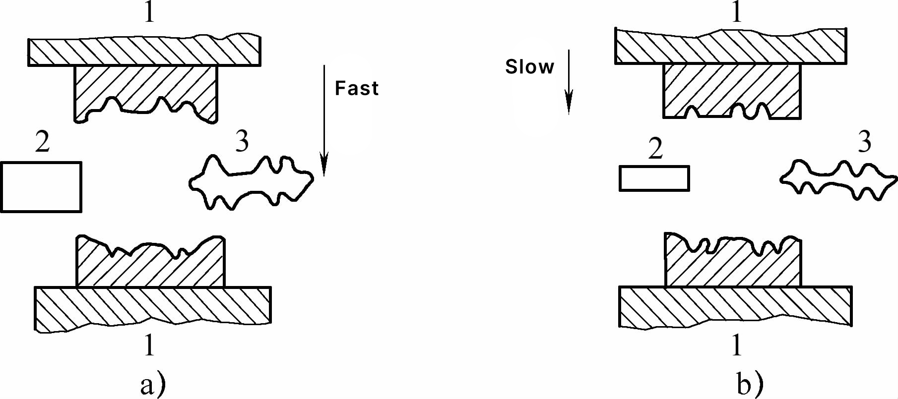 a) Conventional forging b) Isothermal forging 1-mold 2-blank 3-forging |
| Features | Isothermal forming, by overcoming the problem of temperature changes in the billet during conventional thermal deformation processes, has the following characteristics 1) Reduces the deformation resistance of the material. During the isothermal forming process, since the temperature of the billet and the mold are essentially the same, the deformation temperature of the billet does not decrease. At lower deformation speeds, the material softening process is more sufficient, reducing the material’s deformation resistance. Additionally, it is possible to use a range of excellent process and performance lubricants to further reduce deformation resistance, and choose low-power equipment that occupies less space and saves energy. 2) Improves the plastic flow ability of the material. One of the prominent features of isothermal forging is that it can enhance the material’s plastic flow ability. Since the temperature of the billet during isothermal forging does not decrease and the deformation speed is relatively low, this prolongs the deformation time of the material, allowing the softening process to be fully carried out, enhancing the material’s plastic flow ability, and healing defects. This makes the forming of complex shapes with narrow ribs and thin bellies possible, and also provides an effective means for forming low-plasticity, difficult-to-deform materials. 3) High dimensional accuracy of forming, good surface quality, uniform structure, and excellent performance. During isothermal forging, since the deformation temperature of the billet is essentially constant, the material can be formed at a lower deformation temperature, and one-fire forming can be used. The billet heating temperature during isothermal forging is 100~400°C lower than conventional thermal deformation, and the heating time is reduced by 1/2~2/3, thereby reducing defects such as oxidation and decarburization, and improving the surface quality of the product. Since the internal temperature distribution of the billet is relatively uniform, under good lubrication conditions, the deformation of the billet can be uniform, thus the product structure is relatively uniform, achieving the best performance. Additionally, due to the low deformation resistance of the material and small fluctuations in deformation temperature, the elastic deformation of the mold is reduced, which is beneficial to the stability and control of the product’s geometric dimensions. When forming at lower deformation speeds, since the material softening process is more sufficient, the internal residual stress of the formed parts is small, thereby reducing the deformation of the formed parts during cooling and heat treatment, and improving the dimensional accuracy of the products. 4) Long mold life. Although the mold materials and processing costs used in isothermal forming, especially isothermal forging, are higher and the precision requirements are also higher, during the isothermal forging process, since the mold works under quasi-static load, low pressure, and no alternating thermal stress conditions, and can use a series of lubricants with excellent process and performance, the mold life is higher than that of conventional thermal deformation molds. Isothermal forming parts are usually formed in one process, only requiring one set of molds, while conventional thermal deformation generally requires multiple processes, needing multiple sets of molds. Therefore, overall, using isothermal forging can increase mold life and reduce mold costs. 5) High material utilization. Isothermal forging can reduce metal consumption by reducing machining allowances and improving product dimensional accuracy. For example, the raw material used for producing the same turbine engine part in isothermal forging is only about 1/3 of that used in conventional thermal forging. |
| Scope of application | 1) Forming of low plasticity materials. Using isothermal forming methods, materials with low plasticity and difficult to deform, which cannot be processed by conventional deformation methods, can be formed. For example, titanium alloys, high-temperature alloys, and many high-alloy steels, which have a relatively narrow deformation temperature range, make deformation under isothermal conditions very important. Using isothermal forming methods, cobalt-chromium-tungsten-molybdenum alloy can be unidirectionally compressed to 60% without lubrication at a deformation temperature of 900°C and a strain rate of 5×10^0 //s without cracking the billet; at a deformation temperature of 900°C and a strain rate of 2×10^1 /s, gray cast iron can be unidirectionally compressed to 53% without cracking the billet. Currently, isothermal forming processes have been widely applied to the forming and processing of alloy steels, titanium alloys, aluminum alloys, intermetallic compounds, composite materials, and powder materials. With the development of materials science, isothermal die forging processes will play an important role in the preparation and processing of new and difficult-to-deform materials. 2) Forming of high-quality or precious materials. With the development of the aerospace industry, the requirements for structural materials are also increasing. To improve the functionality of aircraft and various modern control devices, high-quality or precious materials such as titanium and titanium alloys, copper and copper alloys, as well as high-temperature alloys, composite materials, etc., are needed. Forming these high-quality or precious materials using conventional thermal deformation methods usually requires increasing the machining allowance, significantly raising material costs and machining costs, causing unnecessary waste. For example, some aircraft titanium alloy parts, due to their complex shapes and very high quality requirements, have a material utilization rate of only about 5% to 15%, with most of the material becoming scrap due to machining. Also, due to the difficulty of machining titanium alloys, machining costs and tool costs are 5 to 10 times higher than other materials. However, using isothermal forming processes, forgings with small draft angles or no draft angles, as well as forgings with distinct stepped sections and small transition radii can be formed, greatly reducing machining allowances, saving materials, and reducing costs. For example, disc-shaped parts with blades manufactured using isothermal die forging methods do not require cutting after forming, saving over 50% of materials compared to conventional thermal deformation methods. 3) Forming of complex high-precision parts. Using isothermal die forging methods, structural parts with high narrow ribs, thin webs, and complex shapes with high dimensional accuracy can be formed, which are often very difficult or even impossible to form using conventional plastic processing methods. Isothermal die forging technology has replaced riveted and screw-fastened assemblies, which were previously mainly manufactured by machining, with large integral structural components, increasing the possibility, reducing costs, and lightening component weight, having a significant impact on the design and manufacturing of aircraft and spacecraft. 4) Forming of large structural parts using low pressure. Isothermal conditions can expand the range of process parameters for material forming, for example, by lowering the strain rate, materials can have higher plasticity at lower deformation temperatures, reducing forming pressure. For instance, when lacking the required high-power equipment, reducing the strain rate and using the billet’s holding pressure in the mold can achieve the forming of large structural parts. |
2. Principles of isothermal forging and mold design
Isothermal forging design is closely related to the process methods and mold structures used during forming, therefore, during the design of forgings, the process methods used should be considered simultaneously, whether it is open die forging or closed die forging, forging with allowance or without allowance, integral mold or composite mold, etc.
Principles of isothermal forging and mold design are shown in Table 19.
Table 19 Principles of isothermal forging and mold design
| Design principles | Content |
| Isothermal forging | 1) Selection of parting line location for forgings. Flat parting should be used as much as possible. For open-die forging, it is the same as conventional open-die parting; for closed-die forging, combination molds are often used, and considering the ease of removing the forging after forging, multi-directional flat parting or curved parting should be adopted. The schematic diagram of the forging parting is shown in Figure 1.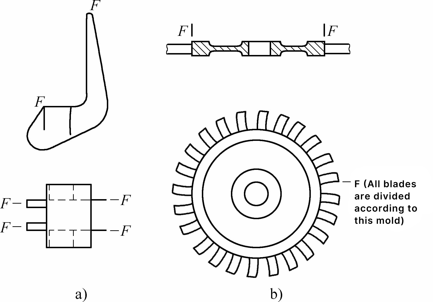 Figure 1 Schematic diagram of forging parting a) Guard plate joint b) Integral turbine 2) Determination of forging draft angle. In open-die forging, the forging draft angle is selected according to recommended values, and a smaller value is chosen when there is an ejector device. In closed-die forging, the external draft angle α on the parting face is 0, and generally 30’~3° in other areas, the internal draft angle β can be 30’~1°30′. Since closed-die forging often uses combination insert molds, the shrinkage rate of the mold material is greater than that of the forging material, and the inserts and forgings are removed from the mold base after cooling in the atmosphere, making the inserts easy to remove from the forgings. The relationship between the forging and the inserts is shown in Figure 2. 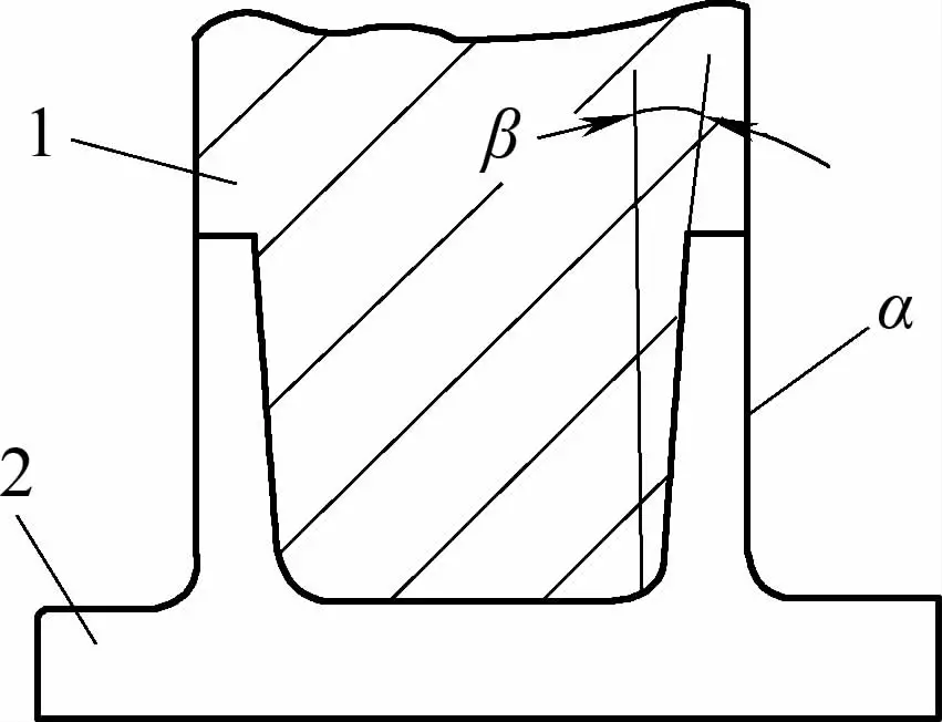 Figure 2 Relationship between forging and inserts 1—Insert 2—Forging 3) Determination of fillet radius. The fillet radius is one of the main factors affecting metal flow and mold life. In isothermal forging, due to multi-directional parting and multi-insert structures, the convex fillet radius on the parting face can be 0, and in other areas, it is the same or slightly smaller than conventional forging; the concave fillet radius should not be too small, mainly considering that during isothermal forging, the blank is primarily pressed into shape in the mold, and a large fillet radius facilitates metal flow and avoids defects. The relationship between the forging fillet and parting location is shown in Figure 3. 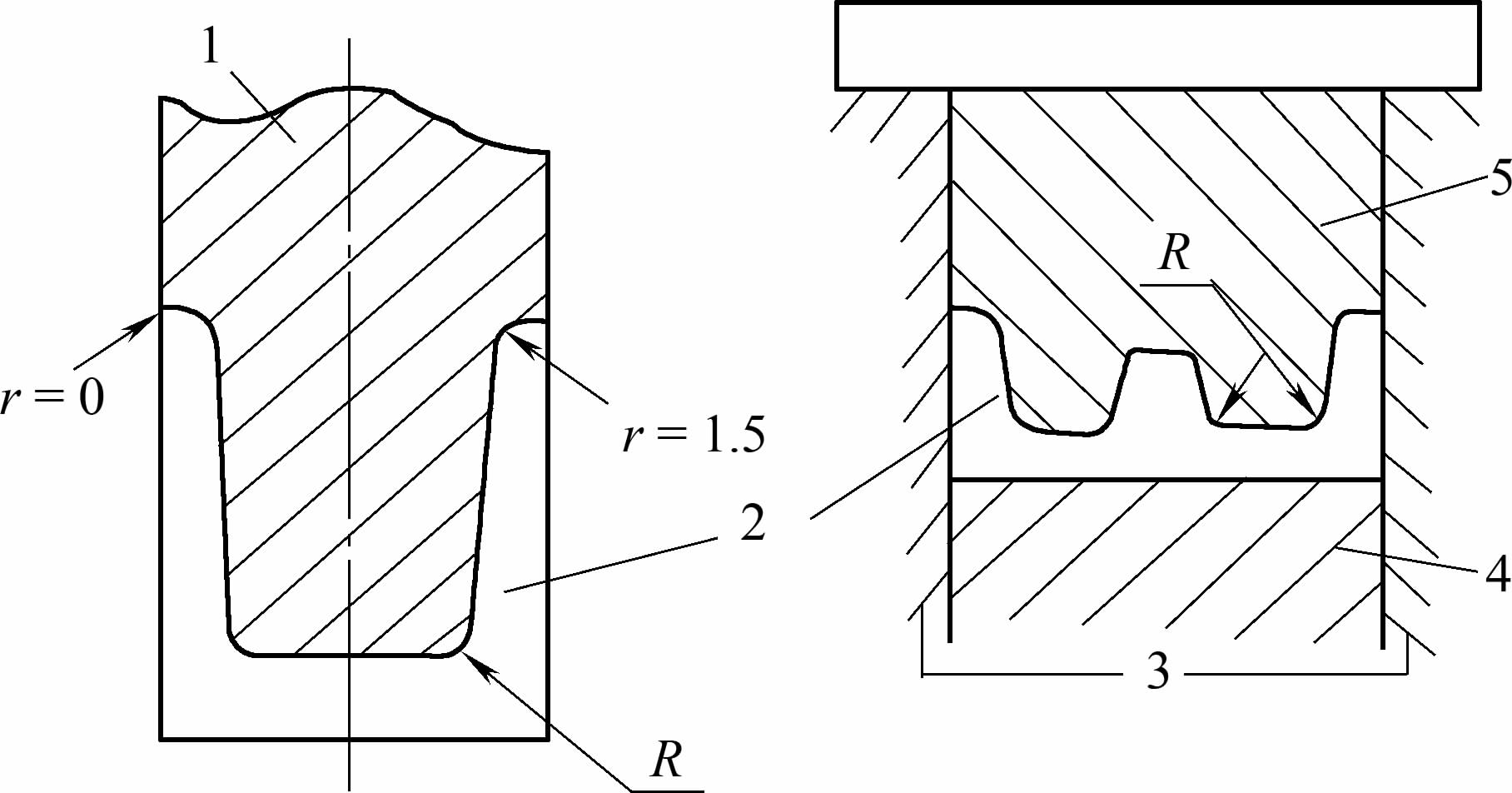 Figure 3 Relationship between forging fillet and parting location 1—Module 2—Forging 3—Mold 4—Lower core 5—Upper press mold 4) Determination of allowance and tolerance. Isothermal forging is mainly used for the forming of non-ferrous metals, which requires lubrication and protection during forming. After forming, the treatment and processing of the forging surface determine whether additional allowance is added. |
| Isothermal mold | 1) Select those forgings that are complex in shape, difficult to form in conventional forging, or require multiple firings, and forgings with very strict requirements on structure and performance as isothermal forgings. 2) Choose open or closed die forging methods according to the structure, size of the forging, subsequent processing requirements, and equipment installation space. 3) The overall design of the mold should meet the requirements of the isothermal forging process, be structurally reasonable, and easy to use and maintain. 4) The forging mold part should have specialized heating, heat preservation, and temperature control devices, and be able to reach the temperature required for isothermal forging. 5) Except for special forgings that require specialized molds, molds should be designed to be universal. 6) Reasonably select the materials used for different parts of the mold to ensure reliable performance of the mold parts at different temperatures. 7) The temperature of the isothermal forging mold is high, to prevent heat loss and excessive conduction to the equipment, an insulating layer should be set between the mold base and the bottom plate, and water channels should be opened in the upper and lower bottom plates for cooling; attention should also be paid to electrical insulation to ensure normal operation of the equipment and safety of production personnel. 8) Consideration should be given to guidance and positioning issues. Since the isothermal forging die is placed in the heating furnace, it is not possible to detect if the die has shifted. Guidance devices should be considered on the die frame and die module, and the internal and external guidance devices should be coordinated; at the same time, positioning blocks should be designed when the blank is placed into the die to prevent the blank from being misplaced. |
3. Mold device for isothermal forging
To make the mold for isothermal forging easy to heat, insulate, and maintain, the general structure of the isothermal forging device obtained from the design and usage experience of scientists from various countries is shown in Figure 1.
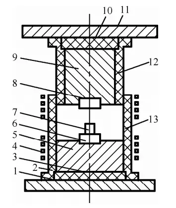
1, 11 – Spacer plate
2, 12 – Insulation cover
3, 10 – Insulation spacer plate
4 – Induction heater
5, 9 – Die base
6 – Lower die
7 – Rough
8 – On mold
13 – Loading and unloading port
V. Powder Forging
1. The essence, advantages, and applications of powder forging
Table 20 The essence, advantages, and applications of powder forging
| Project | Content |
| Process essence | Powder forging is a new method of metal processing that combines powder metallurgy with precision die forging. It uses metal powder as raw material, which is formed by cold pressing, sintering, hot forging, or by hot isostatic pressing of powder, isothermal die forging, or direct hot isostatic pressing and subsequent processing to produce the required shape of precision forgings. A typical powder forging process flow is shown in the diagram below.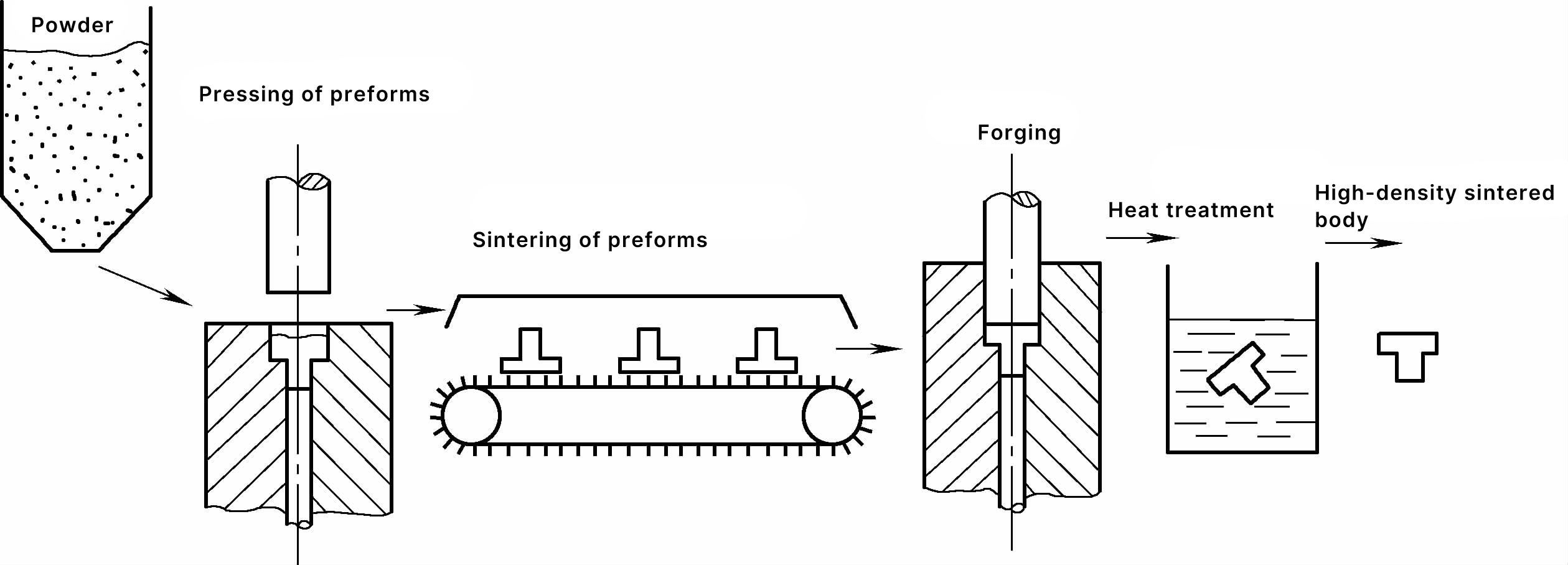 Typical powder forging process flow General powder metallurgy parts contain a large number of pores, poor compactness, and a density usually between 6.2 and 6.8 g/cm³. After hot isostatic pressing or heated forging, the relative density of the parts can be increased to over 98% |
| Advantages | The blanks for powder forging are sintered bodies or extruded billets, or blanks that have undergone hot isostatic pressing. Compared to forging with ordinary steel billets, the advantages of powder forging are as follows 1) High material utilization rate. There is no material loss during preform forging, and the final machining allowance is small, with the overall material utilization rate from powder raw material to finished parts reaching over 90% 2) High dimensional accuracy of forgings, low surface roughness, and easy to obtain complex-shaped forgings. Powder forging preforms use minimal or no oxidation protection heating, achieving precision forging and casting levels in terms of forging accuracy and surface roughness. Optimal preform shapes can be used to facilitate the final forming of complex-shaped forgings 3) Conducive to improving the mechanical properties of forgings. Since the powder particles are formed by the rapid condensation of minute liquid metal, and the composition of the metal droplets is almost identical to that of the parent alloy, segregation is limited within the size of the powder particles. This can overcome defects such as casting segregation and uneven coarse grains in ordinary metal materials (especially for non-solid phase transformation metals and some new materials), making the material uniform and isotropic, which is beneficial to improving the mechanical properties of forgings. However, the presence of certain amounts of pores and inclusions in powder forgings can reduce the plasticity and toughness of the forgings 4) Low forging cost, high productivity, and easy automation. The raw material costs and forging fees for powder forgings are similar to general die forging, but compared to general die forgings, they have higher dimensional accuracy and lower surface roughness, which can reduce or eliminate machining, thus saving a significant amount of labor. For complex-shaped, large-batch small parts such as gears, spline shaft sleeves, connecting rods, and other difficult-to-machine parts, the savings are particularly significant 5) Since metal powder is easy to alloy, it is possible to design and prepare raw materials according to the service conditions and performance requirements of the product, thus changing the traditional forging processing mode of “processing according to supplied materials,” which is conducive to the integration of product process and materials |
| Applications | Powder metallurgy forging is commonly used for various steel powder parts. Currently, dozens of types of steel are used, ranging from ordinary carbon steel to various low-alloy steels, as well as stainless steel, heat-resistant steel, ultra-high strength steel, and other high-alloy steels and high-speed tool steels. For example, powder metallurgy heat-resistant steel has been tested on gas turbine disks, aiming to improve performance. Non-ferrous metal powder forging is not as widely used and mature as steel powder forging. In the aerospace industry, it mainly involves the powder forging of high-temperature alloys, titanium alloys, and aluminum alloys, such as high-temperature alloy turbine disks, titanium alloy fan disks, and aluminum alloy aircraft beam joints. |
2. Requirements for the main processes of powder forging
Table 21 Requirements for the main processes of powder forging
| Item | Content |
| Raw material preparation | Powder raw materials have a significant impact on the performance of powder forgings, but high-quality powder is costly, so it is necessary to reasonably select powder raw materials according to different requirements of powder forgings. Powder raw materials often contain various inclusions, including foreign metal particles and non-metal particles, mostly introduced during the powder raw material and processing stages, especially brittle ceramic inclusions which greatly affect mechanical properties. Therefore, it is necessary to limit the inclusions in powder raw materials, which can be achieved by methods such as magnetic separation or by using vacuum double electrode arc remelting, electron beam cold hearth refining master alloys, and other methods to reduce them to specified limits. The particle size and composition of the powder directly affect the physical and process properties of the powder, and should be included in quality control items. The material ratio and technical requirements for automotive planetary gear powder forging raw materials are shown in Table 22. Ingredients include total loss system oil and zinc stearate as pressing lubricants. The gas content in the powder mainly refers to oxygen content. Oxygen exists in various powder alloys in the form of oxides. The form of oxides varies, and so does their impact on the performance of powder forgings. Most metal powders are oxidized during storage and transportation, and usually undergo reduction treatment before blending. Carbon steel or copper-molybdenum steel powder can be reduced using natural gas or coal gas, low-alloy steel and copper powder can be reduced using decomposed ammonia, and alloy steel powders containing elements like chromium, manganese, and vanadium must be reduced using high-purity hydrogen. Reduction treatment is carried out at a certain temperature, and various process parameters should be adjusted to minimize the residual oxygen content in the powder. |
| Blank preparation | During the design of the blank, it is necessary to carefully analyze and predict the stress and strain state of the key parts of the blank during forging, adjust the geometric shape and size of the blank to prevent forging cracks. For example, during the powder forging of straight spur gears, the projection of the blank in the direction of forging pressure is basically consistent with the forging, and there is only height compression during forging with very little lateral flow. For planetary bevel gears, the shape and size of the blank are shown in Figure 1, the blank shape is relatively simple, very different from the forging, with large metal lateral flow, large forging deformation, good pore elimination effect, and beneficial to improve the performance of the forging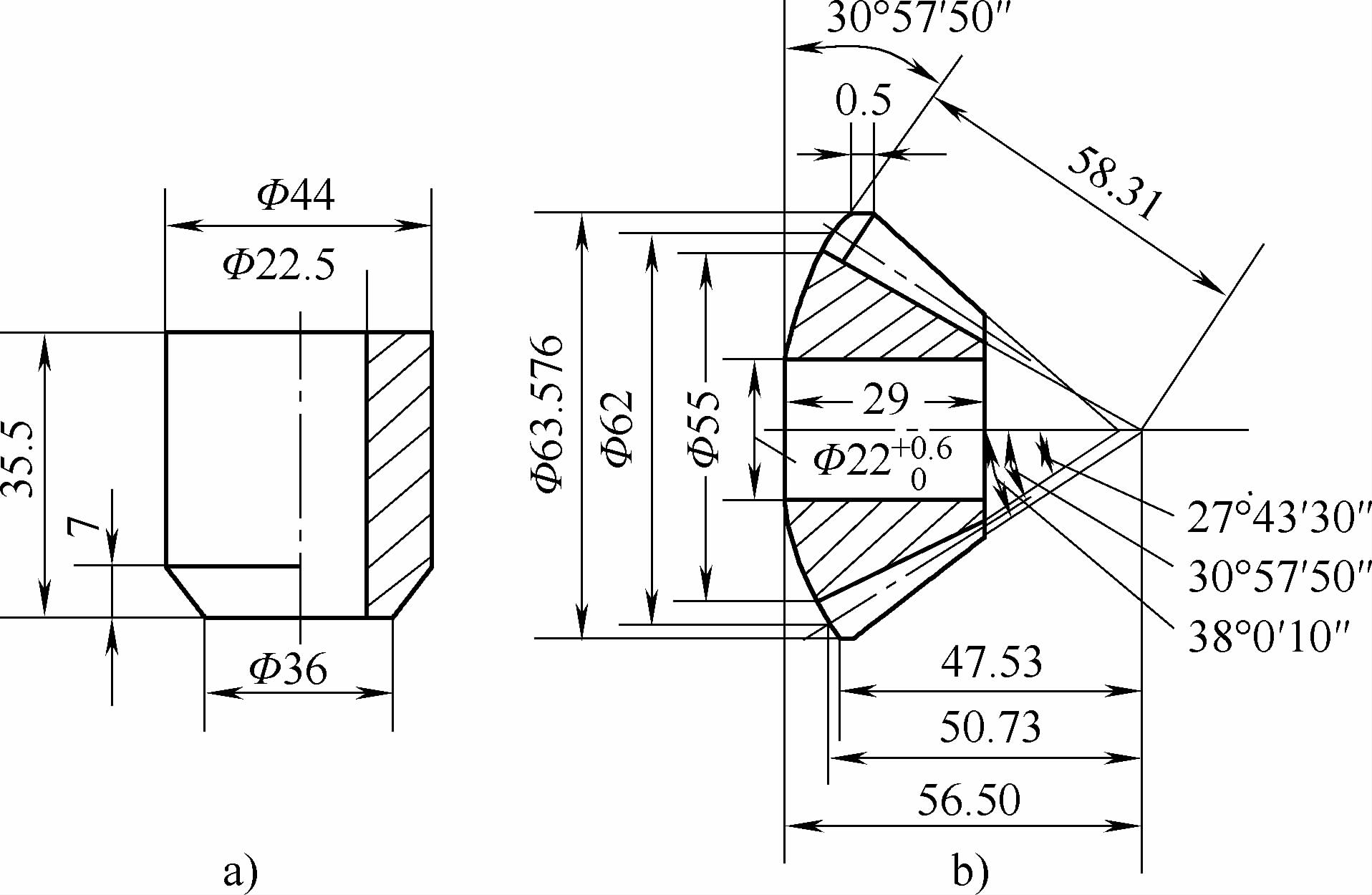 Figure 1 Planetary Gear a) Blank b) Precision forging When pressing the blank with a cold press mold, it is necessary to control the volume or mass of the powder loading to reduce the mass deviation of the blank. An overweight blank will cause the height of the powder forging to exceed the standard, and insufficient mass will cause the height of the powder forging to be insufficient or the density to be insufficient. Attention should also be paid to mold wall lubrication during cold pressing The purpose of sintering is to increase the strength and forgeability of the blank, avoid cracks during forging, homogenize the alloy composition, and sometimes reduce the oxygen content. Sintering is carried out in a protective atmosphere or vacuum. For example, the sintering of automotive planetary bevel gear blanks is carried out in a molybdenum wire furnace with decomposed gas, with a sintering temperature of 1120-1180°C, holding time of 1.5-2.0 hours, and a flow rate of decomposed ammonia as the protective gas of 1.5-2.0m³/h During the sintering of the blank, the volume shrinks, but it still contains a large number of pores. The densification mechanisms of sintering include volume diffusion, grain boundary movement, and diffusion creep When pressing high-temperature alloy powder blanks by extrusion or hot isostatic pressing, they should be sheathed in ammonia protection or placed in a ceramic sheath, then degassed at room temperature and hot state under vacuum, followed by sealing welding, sandblasting, and lubricant coating before extrusion or direct hot isostatic pressing |
| Forging | Common forging equipment for powder forging includes: friction press, crank press, hydraulic press, high-speed hammer, etc. Powder forging generally uses closed die forging, and open die forging is less effective. The size of the forging die groove is determined by adding the shrinkage rate to the size of the forging. The surface roughness of the forging die groove should be low, and appropriate lubricants should also be selected. Pre-forging heating is generally carried out in a protective atmosphere, or high-frequency induction heating can be used, and a protective agent is applied to the surface of the blank. The forging temperature, holding time, and forging pressure for powder forging can be determined by referring to conventional die forging to ensure smooth deformation of the blank and high density in all parts of the forging. The densification of powder forged parts occurs during sintering extrusion, hot isostatic pressing, and plastic forming processes. During plastic forming, the deformation of powder particles reduces and eventually eliminates pores, thus densifying the material, as shown in Figure 2. Experimental results show that the effect of densification depends on the temperature, and under the same degree of deformation, cold deformation is less effective than hot deformation, as shown in Figure 3. Therefore, the heating temperature is an important parameter in powder forging. 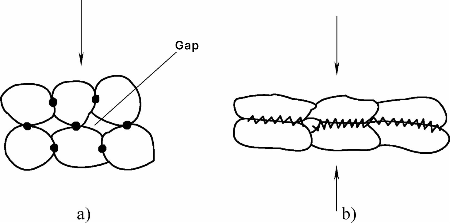 Figure 2 Model of densification mechanism during plastic deformation a) Sintered bonding before plastic deformation b) Plastic deformation bonding after plastic deformation 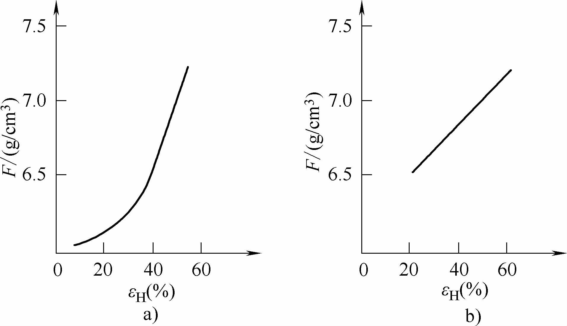 Figure 3 Relationship between upset forging reduction and density a) Room temperature b) 1100°C During powder upsetting, the die should be preheated to a certain temperature, otherwise the chilling effect of the die walls will affect the density and mechanical properties of the surface layer of the billet. After forging, powder forgings should be cooled in a protective atmosphere to prevent oxidation of surface and internal residual pores. |
| Subsequent treatment and processing | During forging, due to the short holding time, although the voids inside the billet are forged together, some parts have not yet fully diffused and combined. This can be improved by annealing, re-sintering, or hot isostatic pressing to ensure full diffusion and bonding. Powder forged parts can undergo various heat treatments just like conventional forgings. To ensure assembly accuracy, powder forged parts sometimes require a small amount of machining, such as grinding the teeth of transmission gears after carburizing and quenching. |
Table 22 Powder Raw Material Proportions and Technical Requirements
| Composition | Fe | Mo | C (Graphite) | Cu | Oil for total loss system | Zinc stearate |
| Content (mass fraction) | Remainder | 0.38%~0.44% | 0.4% ~0.45% | 2.00% | Plus 0.1% | Plus 0.4% |
| Technical requirements | Particle size 100 mesh, annealed in wet and dry hydrogen | Flake graphite powder, purity >98%, particle size 200 mesh | Purity 99%, 200 mesh electrolytic copper powder | L-AN22 | Chemically pure, light zinc stearate | |
VI. liquid die forging
1. Process flow and advantages of liquid die forging
Table 23 Process flow and advantages of liquid die forging
 Liquid die forging process a) Melting b) Pouring c) Applying pressure d) Ejection | |
| Process flow | Liquid die forging uses molten metal as raw material, which is directly poured into the metal mold cavity. Over a certain period, a specific pressure is applied to the liquid or semi-solid metal, causing it to crystallize and undergo minor plastic deformation, thereby obtaining the required forging. The process flow of liquid die forging can be divided into four steps: melting, pouring, mold closing and pressing, and ejection (see above figure). |
| Advantages | Liquid die forging is a process method between casting and forging, thus it possesses the advantages of both casting and forging processes. 1) Liquid die forging is applicable to various non-ferrous metals, carbon steel, stainless steel, as well as brittle gray cast iron and ductile iron, with non-ferrous metals being more commonly used currently. 2) Capable of producing complex parts with high precision and low surface roughness. The precision generally reaches level 3 to 5, and the surface roughness is between 1.6 to 6.3μm. 3) Metal solidifies and crystallizes under pressure, resulting in a dense structure and good mechanical properties. 4) Easy to fill and shape, requiring less forming force, about 1/4 to 1/3 of die forging, which can reduce the tonnage of pressing equipment 5) The mold structure is relatively simple, has a long service life, high material utilization rate, and low production cost |
2. Classification and characteristics of liquid die forging process methods
Table 24 Classification and characteristics of liquid die forging process methods
| Classification | Schematic | Characteristics | |
| Flat punch pressure | Direct pressure method | 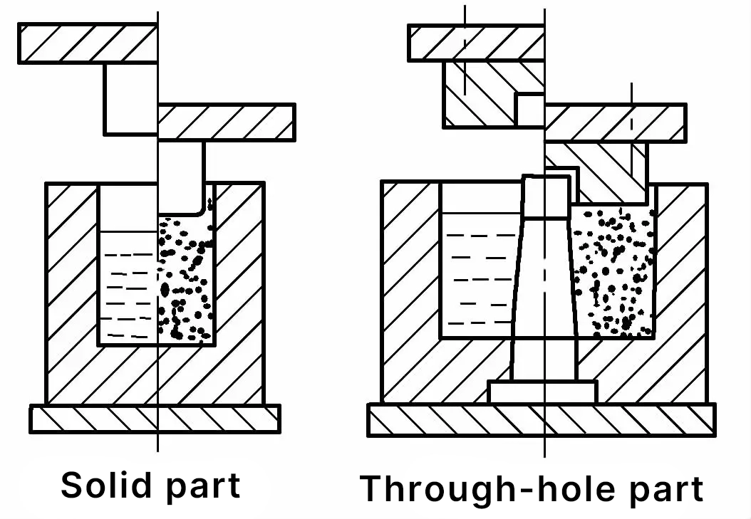 | The part forming is achieved in the metal liquid poured into the die cavity. When the punch is pressed, the metal liquid does not flow significantly, only causing the liquid metal to crystallize and shrink under pressure. It is suitable for manufacturing blanks for pressure processing and through-holes, or cup-shaped thick-walled parts (greater than 5mm) with not too complex shapes. |
| Indirect pressure method | 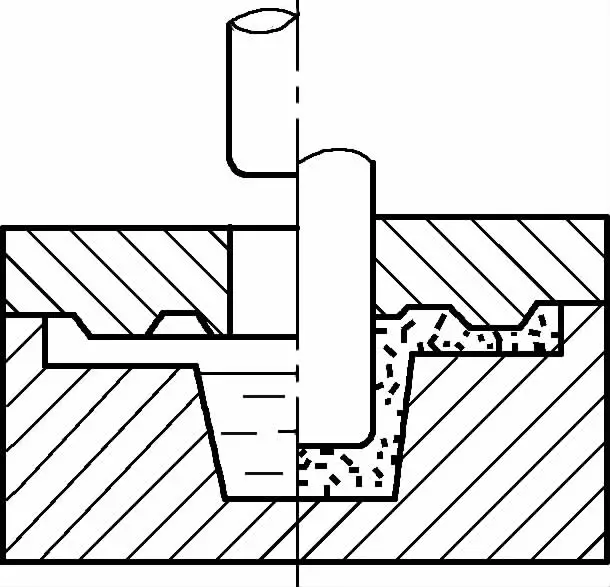 | The part is formed inside the mold cavity after the mold is closed. At this time, the function of the punch is to squeeze the molten metal into the mold cavity, and transmit the pressure to the part through the ingate formed by the punch and the concave mold. The forming method is similar to pressure casting, except that the ingate is wider and shorter, and the molten metal is continuously and slowly squeezed into the working mold cavity, improving the pressurization effect. This process is suitable for production of large quantities, complex shapes, or small parts. | |
| Irregular punch pressure | Convex punch pressure | 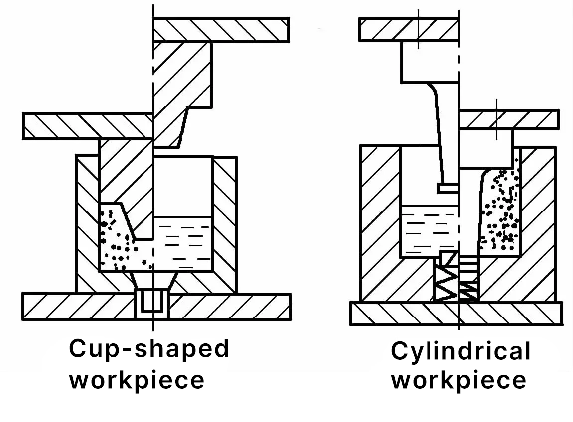 | Part forming is achieved after the mold is closed and pressure is applied. During the forming process, the metal liquid flows upward and radially along the lower mold wall and the upper mold end face to fill the mold cavity. When pressure is applied, the punch directly presses on the upper end face and inner surface of the part, resulting in better pressurization. It is suitable for forming parts with thin walls (greater than 2mm) and complex shapes. |
| Concave punch pressure | 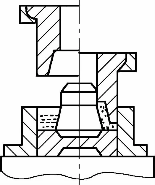 | After the mold is closed and pressure is applied, the molten metal flows along the inner wall of the concave mold and the concave wall of the punch in the opposite direction of the pressure application, to fill the mold cavity, suitable for axisymmetric, complex-shaped hollow parts. | |
| Composite punch pressure | 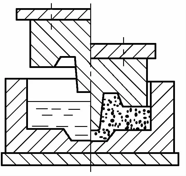 | The pressure punch has a concave notch, and when the mold is closed and pressure is applied, most of the metal does not move, and a small part of the metal directly fills the concave notch of the punch and solidifies under pressure. The liquid forged part of the flange is shown in the left figure. | |
3. Classification and characteristics of hydraulic forging equipment
Liquid die forging equipment uses hydraulic presses, which are easy to control in terms of pressure and pressing speed, and can maintain pressure. See Table 25 for the classification and characteristics of hydraulic die forging equipment.
Table 25 Classification and Characteristics of Liquid Die Forging Equipment
| Classification | Characteristics |
| General hydraulic press | General hydraulic presses can press parts with complex shapes, such as solid, ring-shaped, through-hole, and tubular parts; for some slightly complex parts, necessary process devices can be added. |
| Ordinary special hydraulic press | Ordinary special hydraulic presses are generally based on the general vertical hydraulic press, with hydraulic cylinders installed in horizontal or vertical directions, and some parameters adjusted according to process requirements. |
| Universal special hydraulic press | Side cylinders and auxiliary vertical hydraulic cylinders are installed on the same vertical hydraulic press, giving it both horizontal and vertical clamping forces as well as vertical pressing force. The performance and structural parameters of the Russian УЛМ-2 type universal special hydraulic press are shown in Table 26. |
| Special-purpose hydraulic press | Table 27 shows the parameters of hydraulic presses for two large parts in Russia. Among them, Д0437C uses external casting. П0638 is a three-column hydraulic press with a four-station (casting, pressing, ejecting, cleaning, and cooling) rotary table, revolving around a column at a speed of 0.2 m/s. |
Table 26 ULM-2 type universal hydraulic press equipment performance and structural parameters
| Model | УЛМ-2 |
| Main cylinder piston pressure/kN | 350(800) |
| Main cylinder piston return force/kN | 140 |
| Auxiliary moving crossbeam pressure/kN | 180(370) |
| Auxiliary moving crossbeam return force/kN | 30 |
| Side cylinder pressure/kN | 350(800) |
| Side cylinder return force/kN | 30 |
| Main cylinder stroke/mm | 450 |
| Auxiliary crossbeam stroke/mm | 355 |
| Side cylinder piston stroke/mm | 350 |
| Maximum speed of main cylinder piston/(mm/s) | 220 |
| Worktable dimensions (length × width)/mm | 500×500 |
Note: The parameters in parentheses are after using the booster.
Table 27 Hydraulic Press Parameters for Large Parts
| Model | Nominal pressure of the main cylinder piston/kN | Bottom cylinder ejection force/kN | Maximum downward speed of the main cylinder piston/(mm/s) | Number of stations | Remarks |
| Д0437S | 5000 | 950 500 | 200 | Single station | Manual, semi-automatic |
| P0638 | 6300 | Four stations | Manual, semi-automatic |
VII. Multi-directional forging
Multi-directional forging is a specialized process that forges the blank simultaneously in several directions. It overcomes the limitations of forging hammers, hydraulic presses, and crank presses, changes the drawbacks of large, complex forgings such as large remnants, large allowances, and large tolerances, refines the blank, improves internal quality, and thereby greatly enhances productivity.
1. Multi-directional forging equipment
Table 28 Multi-directional Forging Equipment
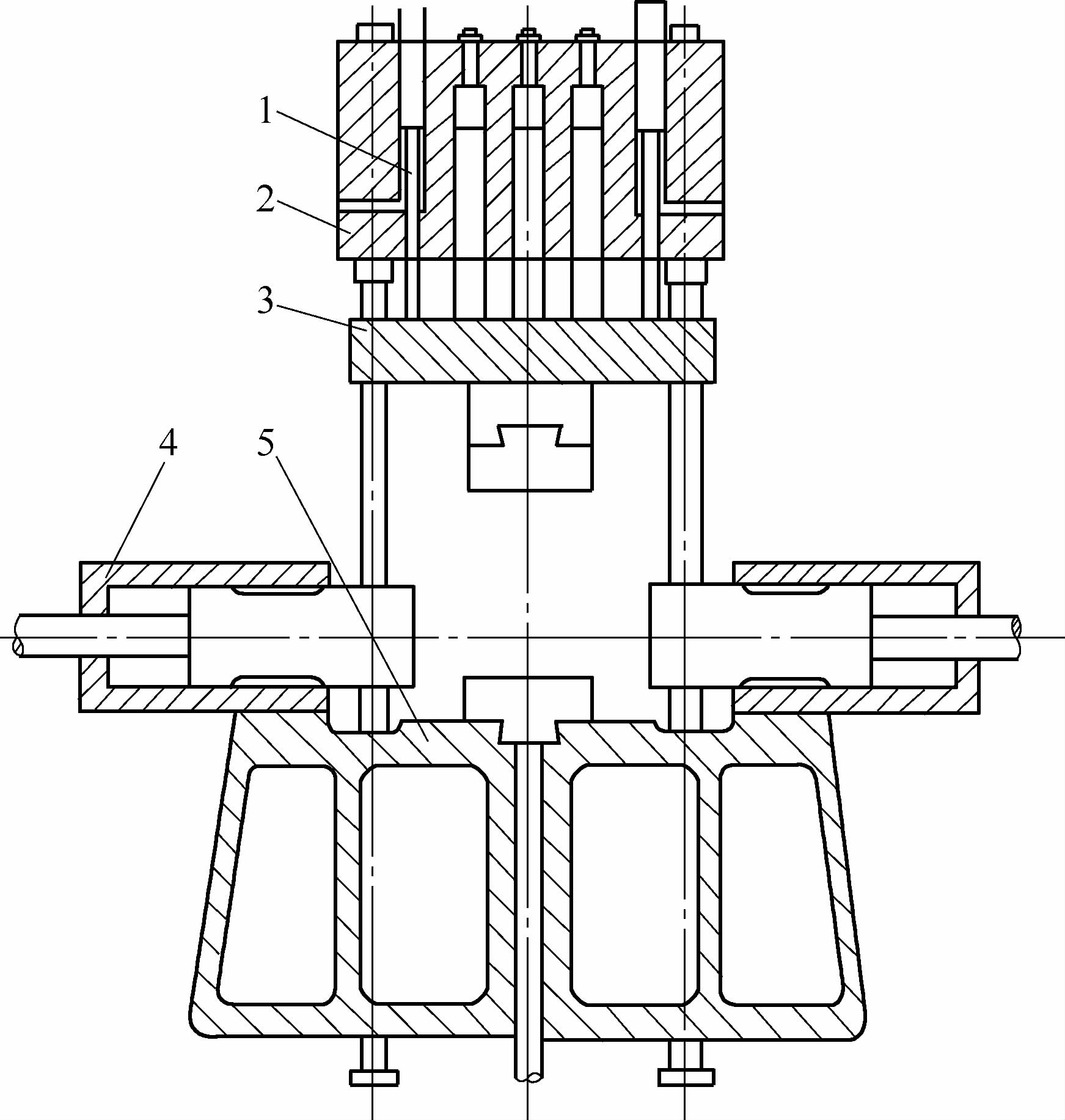 Four-station Multi-directional Forging Hydraulic Press 1—Tie rod 2—Upper crossbeam 3—Moving crossbeam 4—Lateral horizontal working cylinder 5—Workbench |
| Multi-directional forging equipment mainly consists of multi-directional forging hydraulic presses, which are developed based on ordinary hydraulic presses. Two lateral horizontal working cylinders 4 are added on the basis of the ordinary hydraulic press. A module (or punch) is installed on the moving crossbeam 3, the workbench 5, and the horizontal lateral working cylinder, with up to four modules (or punches) that form a pair of molds with a closed-type groove. This type of hydraulic press is called a four-station multi-directional forging hydraulic press, as shown above. In addition to the four-station multi-directional forging hydraulic press, there is also a special hydraulic press composed of an ordinary hydraulic press and four horizontal working cylinders, called a six-station multi-directional forging hydraulic press. Since the molds of the multi-directional forging hydraulic press can consist of several pieces, it can form several parting surfaces. Speaking of multiple parting surfaces, the flat forging machine is also a type of multi-directional forging equipment. The mold of the flat forging machine has two mutually perpendicular parting surfaces, consisting of two die modules (one of which is fixed) and a punch. However, the force of the flat forging machine is in the horizontal direction, and the punch is the main tool for forming the workpiece. The clamping force between the fixed die and the moving die is relatively small, so it is more commonly used to process simple shapes like solid and hollow cylinders and truncated cones. |
2. Multi-directional forging process and typical forgings
Table 29 Multi-directional Forging Process and Typical Forgings
| Project | Content |
| Process Steps | Multi-directional die forging is carried out in a die groove with multiple parting surfaces, as shown in Figure 1. When the blank is placed on the station, the upper and lower die modules close and forge, preliminarily shaping the blank to form a protruding shoulder. Then, installed on the horizontal working cylinder, the punches from left and right press in, and in the die groove formed by the upper and lower modules, the preliminarily shaped forging is punched out to form the required holes. After forging, the punch is first withdrawn, then the upper and lower modules separate, and the forging is removed. Figure 1 Multi-directional die forging process a) Place the blank b) Close the mold and apply multi-directional pressure c) Open the mold (upper mold rises, left and right punches retract) |
| Typical forgings | The shapes of multi-directional die forgings can vary, as shown in Figure 2. Among them, Figure 2a is an aircraft landing gear, a hollow titanium alloy forging; Figure 2b is a hemispherical nickel-based alloy forging; Figure 2c is a large valve body multi-directional die forging, made of 30CrMo alloy structural steel.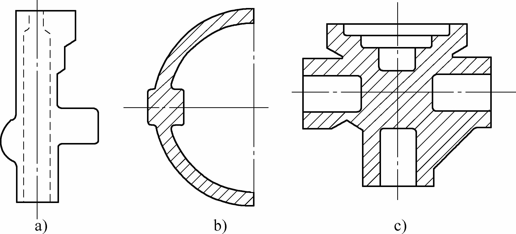 Figure 2 Typical multi-directional die forgings a) Aircraft landing gear b) Hemispherical shell c) Large valve body |
| Advantages and disadvantages | 1) High material utilization. Multi-directional die forging mostly uses closed die forging, the forgings can be designed to be hollow, and can eliminate or set a very small forging taper. With the help of a demolder, forgings are also easy to remove, thus saving a lot of material. Compared to general die forging processes, it can save about 50% of metal, and material utilization can reach 40% to 90%. 2) Good forging performance. Since most shapes are obtained by die forging, the metal flow lines are well arranged, mostly distributed along the contours, and fewer flow lines are cut during machining, resulting in good forging performance. Generally, it can increase strength by more than 30%. 3) Multidirectional die forging is often completed in one heating, which maximally avoids defects and losses caused by heating. This is extremely important for high alloy steels, nickel-based alloys, and titanium alloys, which are expensive and have a narrow forging temperature range. Using multidirectional die forging reduces the number of heatings and oxidation losses, thereby reducing costs and improving quality, which is conducive to mechanization. Equipping with a robotic arm can greatly reduce labor intensity. 4) Wide application range. Multidirectional die forging can process forgings of various complex shapes, and there are fewer restrictions on the size and material of the forgings. In addition to general metal materials, it can also die forge high alloy steels, nickel-chromium alloys, etc., because multidirectional die forging can improve the plasticity of the material. Multidirectional die forging also has some disadvantages. Firstly, it requires the blank to have high shear quality, and the size and weight of the blank must be precise; secondly, after the blank is heated, oxidation scale should be avoided as much as possible, requiring less or no oxidation heating of the blank or setting up a device to remove oxidation scale; it also requires the use of rigid, high-precision specialized equipment or the addition of specialized die forging devices on general equipment. |
VIII. Crankshaft bending upsetting forging process (full fiber forging)
The crankshaft bending upsetting forging process is a specialized process for batch forging of large crankshafts, which can be forged on a specialized hydraulic press, or on a general hydraulic press or crankshaft press with a specialized device (mold).
The essence and method of crankshaft bending upsetting forging are shown in Table 30.
Table 30 The essence and method of crankshaft bending upsetting forging
| Item | Description | |
| Essence of the process | It utilizes the shape characteristics of the crankshaft itself, forging each bend in the mold using the bending upsetting method. Compared to free forging crankshafts, the use of bending upsetting method to produce crankshafts allows the metal fibers to continuously distribute along the exterior of the forged piece, with the centerline of the billet and the axis of the crankshaft essentially coinciding. After machining, the metal fibers are not cut, and defects such as segregation and inclusions in the core of the billet are not exposed. Moreover, finer billets can be used, improving the mechanical properties of the crankshaft. It also significantly reduces the machining allowance, saving about 34% of metal, reducing machining time by 28%, and has the advantages of fewer defects, higher productivity, and reduced labor intensity. | |
| Process method | RR upsetting method | The RR upsetting method is a crankshaft bending upsetting method developed in France in the 1940s, and its working principle is shown in Figure 1. It uses a sliding die frame with an inclined surface to convert the press force of the forging press into a horizontal upsetting force, which remains constant throughout the upsetting process, about 0.4 times the tonnage of the press.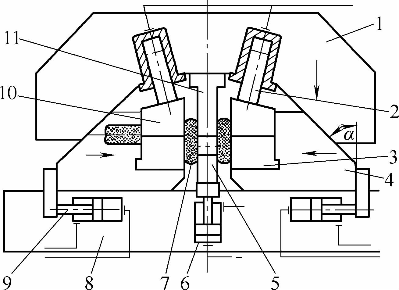 Figure 1 RR crankshaft bending upsetting device working principle diagram 1-Upper die frame 2-Clamping cylinder (four) 3-Positioning clamping module 4-Sliding die frame (left, right one each) 5-Lower punch 6-Ejector cylinder 7-Forging 8-Base plate 9-Side cylinder (two) 10-Clamping module 11-Upper punch In forging the crankshaft, first forge the steel ingot into a round bar, cool it, and then turn out parts equivalent to the main shaft neck and crank pin of the crankshaft, forming a stepped shaft. The depth of the step is generally 10~15mm, and the amount of metal in the crank arm is determined by calculation. Then, the metal to be formed into two crank arms is heated in a local heating furnace. After placing the blank in the mold, close the upper punch 11 and lower punch 5. At this time, modules 3 and 10 clamp the main shaft neck, and the upper and lower punches also tightly clamp the crank pin, preventing it from thickening due to the arm upsetting (the first step of forming forging). Move the left and right sliding die frames 4 to pre-upset (the second step of forming forging). After pre-upsetting to a certain extent, start upsetting while pressing the upper and lower punches, moving the crank pin half a crankshaft stroke from its original position, and the crank arm is also formed in the module (the third step of forming forging). One bend upsetting of the crankshaft is completed. Finally, open the upper and lower molds and take out the formed forging blank of one bend, then heat the next bend. The flange at the end of the crankshaft can also be upset in this device. In upsetting the second bend and subsequent bends, use the previous bend to position in the positioning mold, thus forming one bend (or flange) at a time, and the entire crankshaft can be forged. |
| TR upsetting method | With the development of diesel engines and continuous production practice, it was found that the upsetting force of the RR upsetting method was insufficient, requiring large-tonnage forging presses, generally above 50000kN, to forge large power medium-speed diesel engine crankshafts. Based on these reasons, a TR bending upsetting method was successfully researched in Poland in the 1950s. Its principle is the same as the RR bending upsetting method, but the structure of the bending upsetting device (mold) is more superior, allowing for much greater horizontal upsetting force. It decomposes the press’s pressure into vertical bending force and horizontal upsetting force through a bell crank mechanism, with a more reasonable distribution of forces. During the upsetting process, as the angle of the bell crank α gradually decreases, the horizontal upsetting force gradually increases, reaching its maximum at the end of upsetting, about 1.2 times the nominal tonnage of the press, as shown in Figure 2.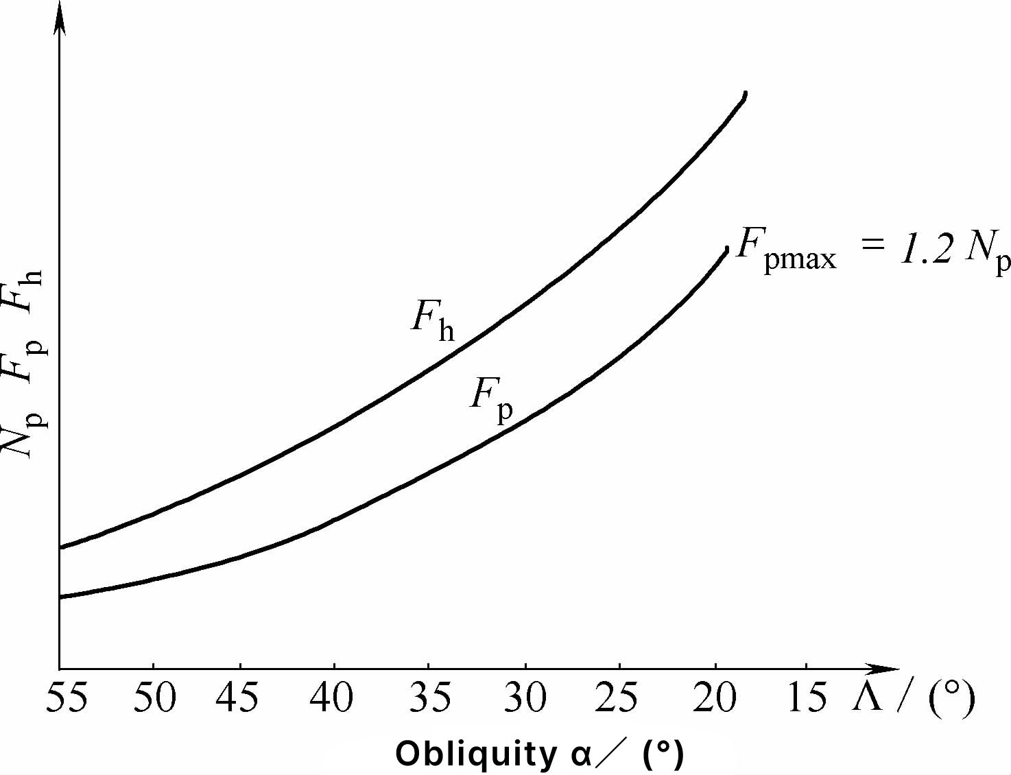 Figure 2 Relationship between upsetting force and bell crank angle α N p — Press tonnage F p — Horizontal upsetting force F h — Theoretical upsetting resistance The trend of the horizontal upsetting force and the change in the forming resistance of the crank arm are consistent. Therefore, the TR bending upsetting device requires a smaller press tonnage, and a crankshaft much larger than that which can be forged by the RR bending upsetting device can be forged with the same tonnage press. In addition, the TR bending upsetting device has a simple structure, is easy to install and dismantle, is lightweight, and can forge crankshafts on a general hydraulic press, and can perform free forging after removing the mold. Due to these advantages, the TR bending upsetting device is gradually replacing the RR bending upsetting device. The working principle of the TR bending upsetting device is shown in Figure 3. The elbow mechanism 7 is connected between the upper die frame 1 (C-frame) and the upper die module 6, and is a key component for decomposing and transmitting force, with four sets including elbows, upper and lower support shafts, upper and lower half shaft sleeves, etc. The vertical component Fv from the elbow mechanism clamps the forging 2 between the upper die module 6 and the lower die module 10, and the horizontal component Fh forges the billet through the sides of the two modules. The clamping and synchronous movement of the upper and lower modules are ensured by their own locks. The lower half mold slides in the guide groove of the base plate 13. The initial position of the upper and lower modules is adjusted and positioned by the limit screw 14. 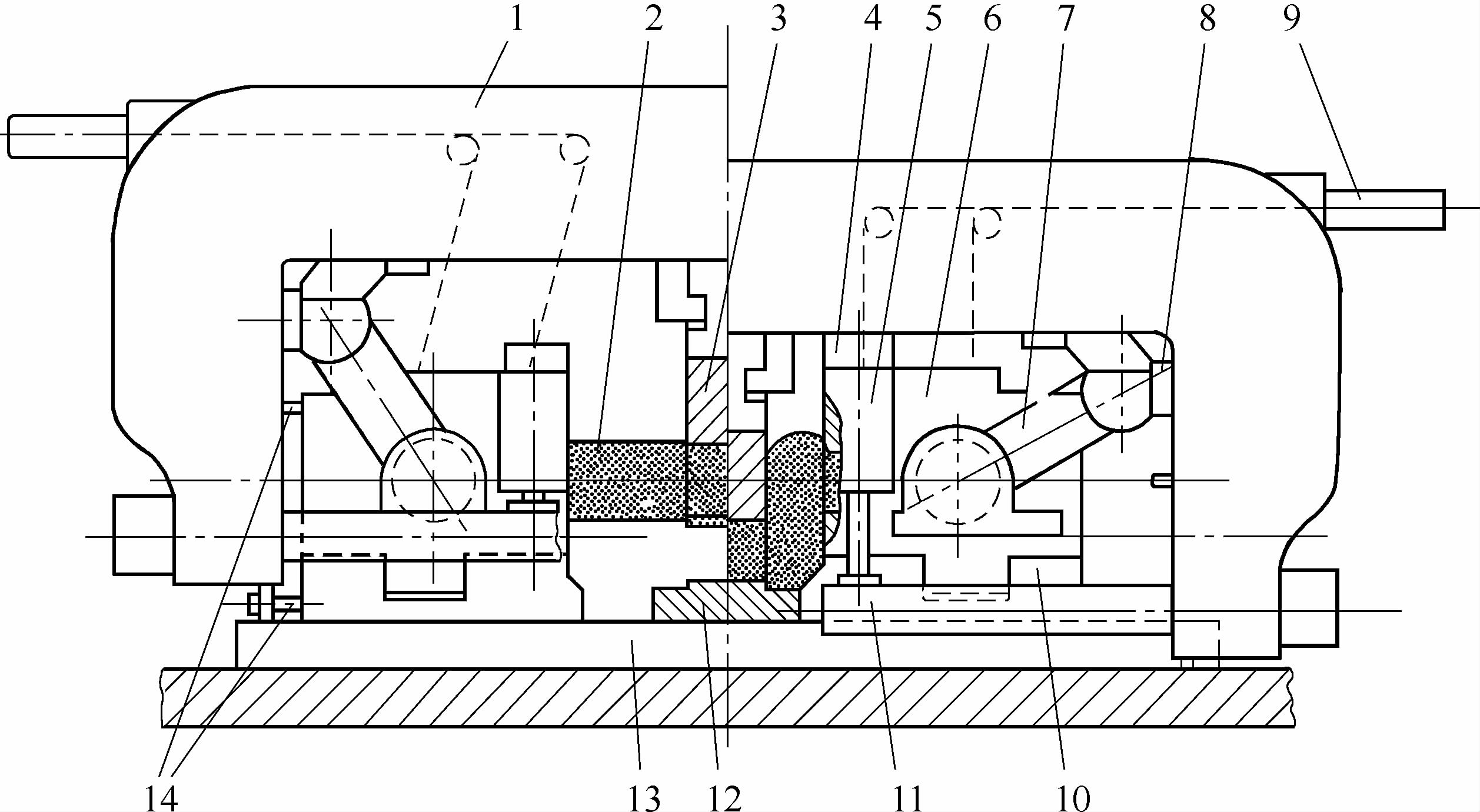 Figure 3 TR crankshaft bending upsetting device working principle diagram 1—Upper die frame 2—Forging 3—Upper punch 4—Adjustment pad (1) 5—Vertical hydraulic cylinder 6—Upper die module 7—Elbow 8—Adjustment pad (2) 9—Upper hydraulic cylinder 10—Lower die module 11—Tie rod 12—Lower anvil block 13—Base plate 14—Limit screw The fork-shaped bending upper punch 3 is installed at the top of the upper die frame, which is easy to install and dismantle. When the bending upsetting starts, it forks at the crank pin position of the blank, pushing the bar material to bend, and finally forms on the stationary lower anvil block 12. The upper die frame is the main load-bearing component and also supports the upper die; it forms a closed load-bearing system with the tie rod 11. Adjustment pads 8 and 4 can be swapped for different crankshafts to adjust the upsetting amount and misalignment. Four upper hydraulic cylinders 9 are installed on the outer side of the top of the upper die frame, which hang the upper die module on the upper die frame through chains and pulleys, mainly to hold the upper die module at the end of upsetting to keep it in place, preventing tilting and slipping, to smoothly remove the upper die module. The vertical hydraulic cylinder 5 assists the upper oil cylinder in balancing. After demolding, the upper hydraulic cylinder and the vertical hydraulic cylinder are depressurized, and the upper die module smoothly returns to its initial position under the influence of gravity. The lower die module resets by the reset cylinder. Two pairs (four pieces) of blocks are installed on the outer side of the lower die module’s crank arm forming slot (see Figure 4). On one hand, it prevents the metal from flowing towards the short axis of the crank arm; on the other hand, the blocks leave the forging only after the upper die module is lifted and the forging is no longer in contact, serving the demolding function. 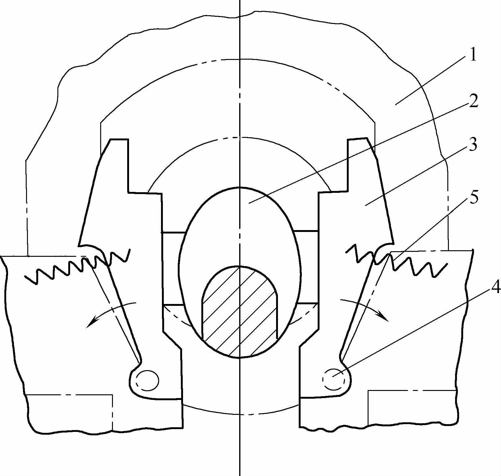 Figure 4 Crank arm forming block diagram 1—Upper module 2—Forged crank arm 3—Stop block 4—Pin 5—Spring | |

