Introduction to Radius Calculators
Purpose of a Radius Calculator
A radius calculator is designed to help professionals in the metal forming industry estimate important parameters when working with press brakes. It aids in determining the required force (tonnage) and the bending radius, given the material’s properties and the desired bend angle.
This valuable tool is essential in ensuring accurate and efficient project planning. By providing reliable estimates, it enables operators to prevent overloading or underpowered press brakes, which could potentially damage equipment and waste resources.
The internal radius R of press brake air bending is approximately 16% of the die opening V. You can use the press brake radius calculator to get the most accurate data.

Min Bending Radius
| No. | Materials | Min bending radius |
| 1 | 08, 08F, 10, 10F, DX2, SPCC, E1-T52, 0Cr18Ni9, 1Cr18Ni9, 1Cr18Ni9Ti, 1100-H24, T2 | 0.4t |
| 2 | 15, 20, Q235, Q235A, 15F | 0.5t |
| 3 | 25, 30, Q255 | 0.6t |
| 4 | 1Cr13, H62(M, Y, Y2, cold rolled) | 0.8t |
| 5 | 45, 50 | 1.0t |
| 6 | 55, 60 | 1.5t |
| 7 | 65Mn, 660SiMn, 1Cr17Ni7, 1Cr17Ni-Y, Cr17Ni-DY, SUS301, 0Cr18Ni9, SUS302 | 2.0t |
- The bending radius refers to the inner radius of the bending part, and t is the wall thickness of the material.
- t is the wall thickness of the material, M is the annealed state, Y is the hard state, and Y2 is the 1/2 hard state.
1. Bending Radius
The degree of bending deformation is represented by the relative bending radius (r/t). The smaller this value, the greater the deformation. When the value of the relative bending radius (r/t) decreases to a certain extent, the outer fibers of the sheet metal exceed the maximum permissible deformation of the material, resulting in tensile rupture damage.
To ensure no cracks occur during bending, it is necessary to limit the degree of deformation, i.e., limit the extreme bending deformation of the sheet metal – the minimum relative bending radius (r/t).
While there exists a minimal bending radius (rmin/t) for any material, it is generally not advisable to use this minimum radius for bending operations. The bending radius should be as large as possible, but not too large as this could increase springback.
The influence of springback makes it challenging to guarantee the shape and size precision of the bent part. Therefore, the bending radius should not be too large or too small; an appropriate selection is necessary.
1.1 Factors Influencing the Minimum Bending Radius
1. Impact of Material Mechanical Properties
The sheet metal to be bent should have sufficient plasticity, relatively low yield strength, and a high modulus of elasticity. A high level of plasticity ensures no cracking occurs during bending (i.e., the minimum bending radius of the sheet metal is small). Lower yield strength and higher modulus of elasticity make it easier to achieve accurate bending shapes. As the thickness of the material increases (t increases), the minimum bending radius also increases.
2. Influence of the Bending Central Angle (α)
Theoretically, the degree of bending deformation only relates to r/t. However, in actual bending operations, when the bending central angle (α) is small, the bending deformation is small, and the adjacent parts of the material may take on more tensile deformation (in the bending deformation area).
Therefore, the allowed minimum bending radius may also be smaller. For instance, if the bending central angle (α) is between 120° to 130°, the rmin is 30% to 50% larger than when the bending central angle (α) is 90°. When a is less than 90°, rmin can be reduced by 20%.
3. Influence of Sheet Width and Hardened Layer of the Sheared Surface
As the width of the sheet increases, the minimum bending radius also increases. However, this effect diminishes when the sheet width increases to about (8~10)t.
The blank before bending is usually obtained by shearing or punching, and the sheared surface has a work-hardened layer that reduces the plasticity of the material, increasing the minimum bending radius. Therefore, when a very small bending radius is required, it is necessary to include an annealing process before bending to eliminate the hardened layer of the blank.
4. Impact of Bending Line Direction
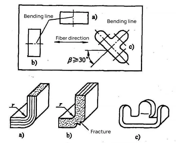
Since most sheet metals for bending are rolled, they exhibit a fibrous structure, with anisotropy in the mechanical properties of the thickness direction and the plane of the sheet. When the bending line is perpendicular to the rolling (fiber) direction, the minimum bending radius of the sheet is smaller.
When the bending line is parallel to the rolling (fiber) direction, the minimum bending radius of the sheet is larger. Special attention needs to be paid to the direction of the bending line for materials with significant anisotropy, like brass and phosphor bronze.
Therefore, during the punching layout, the rolling direction should be considered. The bending radius (r) when the curve is perpendicular to the rolling direction is shown in Figure 1a, and the bending radius (r) when the bending line is parallel to the rolling direction is shown in Figure 1b, where cracking occurs.
Hence, the layout should make the bending line as perpendicular to the rolling direction as possible. When bending smaller parts with bending lines perpendicular to each other, the angle (β) between the bending line and the rolling direction of the sheet should be greater than 30° during the layout, as shown in Figure 1c.

5. Influence of Blank Material Surface and Shearing Quality
When the blank material of a part has defects, or the shearing cross-section is not smooth, has burrs, or is of poor quality, it can lead to stress concentration and cause ruptures. At this point, it is necessary to appropriately increase the minimum bending radius.
Removing burrs before bending, or positioning the side with burrs towards the pressure zone of the punch, can reduce the chance of rupture. The shearing quality significantly impacts the bending of narrower blank materials. As the width of the blank material increases, the impact gradually decreases.
1.2 Determination of Minimum Bending Radius
There are many factors affecting the minimum bending radius of sheet metal, and they are extremely complex. It is difficult to accurately calculate the minimum bending radius using theoretical methods, and it has no practical application significance.
Therefore, the minimum bending radius commonly used in actual production is usually determined by experimental methods. The experimental data for the minimum bending radius (i.e., the radius of the inner arc) of commonly used sheet metals, rmin, is presented in Table 4-1.
Table 1: Minimum Bending Radius of Sheet Metal (Unit: mm)
| Material | Annealed condition | Cold work hardened condition | ||
| Bend line position | ||||
| Vertical Rolling Direction | Parallel Rolling Direction | Vertical Rolling Direction | Parallel Rolling Direction | |
| 08, 10, Q195, Q215 | 0. 1t | 0. 4t | 0.4t | 0.8t |
| 15, 20, Q235 | 0.1t | 0.5t | 0. 5t | 1. 0t |
| 25, 30, Q255 | 0. 2t | 0. 6t | 0.6t | 1. 2t |
| 45, 50, Q275 | 0.5t | 1. 0t | 1.0t | 1.7t |
| 65Mn | 1. 0t | 2. 0t | 2.0t | 3.0t |
| Aluminum | 0.1t | 0.35t | 0. 5t | 1.0t |
| Pure Copper | 0. 1t | 0.35t | 1.0t | 2. 0t |
| Soft Brass | 0. 1t | 0.35t | 0.35t | 0.8t |
| Semi-Hard Brass | 0.1t | 0.35t | 0.5t | 1.2t |
| Phosphor Bronze | – | – | 1. 0t | 3.0t |
Note:
- When the bending line is at a certain angle to the rolling direction, depending on the size of the angle, values between vertical and parallel to the rolling direction can be used.
- When bending unannealed narrow strips in punching or trimming, they should be treated as hardened metals.
- During bending, the side with burrs should be on the inside of the bend.
- The ‘t’ in the table represents the thickness of the sheet metal.
- ① The Q255 grade was discontinued in GB/T 700-2006.
1.3 Techniques to Improve the Degree of Limit Bending Deformation
Generally, it’s not advisable to use the minimum bending radius rmin for bending parts. From a purely technical perspective, the general requirement is r≥t; for thick materials, r=2t. Only when the product structure requires it, should the allowable approach to the minimum bending radius values be used.
When the required part bending radius <rmin, in addition to using some techniques to improve the plasticity of the material (such as annealing, hot bending, etc.) and trimming or polishing the blank cutting surface, the following measures can be adopted:
1) Increase the shaping process, gradually reducing the bending radius r, thus enlarging the bending deformation area and reducing the stretch rate of the outer metal layer to ensure the required inner corner radius of the bent part. For example, using a two-stage bending process: using a larger bending radius in the first bend, then annealing (stress relieving), and the second time bending according to the part’s required corner radius.
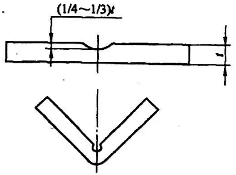
2) For thick materials, it’s essential to start with a process groove, reducing the thickness of the material in the bending part to ensure the requirements of the bent part, as shown in Figure 2.

2. Straight Edge Height of Bent Parts
If it’s necessary to ensure a very straight edge of the bent part during bending, then the straight edge height H should be greater than 2.
When H<2t, the contact surface of the bent edge in the bending mold is too small, making it difficult to form enough bending moment and correction force, and it’s tough to get an accurate shape of the bent part (or impossible to bend and form).
Therefore, when H<2t, it’s necessary to pre-open a process groove or increase the straight edge height dimension, and after the bending is formed, the excess material is cut off, as shown in Figure 3.

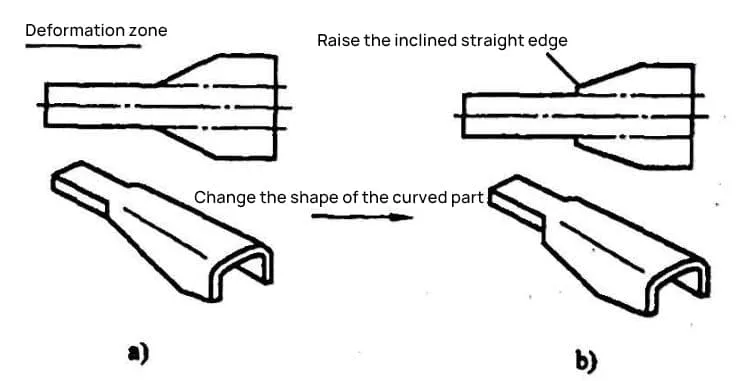
If the straight edge of the bent part has an angle (see Figure 4), and the angle is within the deformation zone, as shown in Figure 4a, it is impossible to bend the section with a straight edge height less than 2t to the desired degree, and it is also prone to cracking. Therefore, it is necessary to change the shape of the part and increase the size of the straight edge of the angle, as shown in Figure 4.


