Comparison of Hydraulic and Mechanical Press Brakes
When it comes to the precision and efficiency of metal fabrication, the debate between hydraulic and mechanical press brakes is…

At first glance, bending dies appear to be relatively regular geometric shapes, much simpler than stamping dies. However, upon examining the brochures of bending die manufacturers, we often find them filled with dozens or even hundreds of pages of technical details. The structural diagrams look incredibly complex. Why is that?

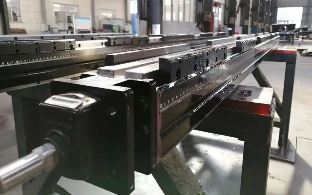
Common CNC press brake tooling can be categorized into upper dies (top punches) and lower dies (bottom dies), intermediate plates (also called quick clamps, which secure the top punch to the press brake’s ram), guide rails (also known as die holders, connected to the bottom dies), and spacer blocks (also called lower die seats, connected to the mechanical compensation worktable and installed on the press brake’s support).
The mainstream press brake rams are upper moving, meaning the top punch is the active die, applying pressure to the sheet metal down into the cavity of the bottom die; the bottom die remains stationary, supporting the metal sheet as the passive die.
Related reading: Press Brake Tonnage Calculator
Press brake tooling is generally divided into standard and special dies.
In terms of shape, upper dies can be classified as standard punch, radius punch, gooseneck punch (most commonly seen), and forming dies.

Typical upper dies have angles of 30 degrees, 60 degrees, and 78 to 88 degrees, while bottom die grooves are approximately at 30 degrees, 60 degrees, and 80 to 90 degrees; radius punches are designed based on the radius and arc length of the workpiece; gooseneck punches are mainly used for U-shaped workpieces or for avoiding interference in multiple bends.
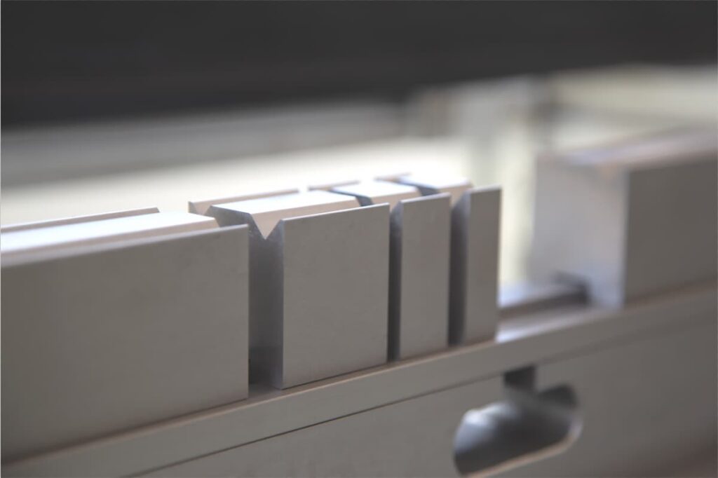
Standard lower dies can be divided based on the number of grooves into: single-V dies, double-V dies, and multi-V dies.
Single-V and double-V dies have one or two grooves on their surfaces and are commonly used for precision bending on medium and small CNC press brakes.
A common standard is the concentric double-V die, where the distance from the centerline of the two V-shaped openings to the centerline of the guide rail slot below is equal.
The advantage of this design is that, for example, when switching from a V8 groove to a V12 groove on the same plane, one can simply pull the die out along the guide rail, flip it and reinsert it into the rail to switch to the V12 groove.
The die automatically aligns itself, and the switch can be completed in a few seconds, which is also convenient for avoiding interference during bending.
Multi-V lower dies can be double-sided multi-V dies or the more common four-sided multi-V dies, with several grooves of different sizes or shapes on each of the four surfaces, suitable for multi-purpose use and adaptable for bending various thicknesses of sheet metal.

When switching grooves, screws need to be turned to rotate the die and recenter it, generally used for large press brakes and conventional bending machines.
Additionally, there are adjustable opening lower dies, where the size of the groove can be adjusted according to customer requirements. These dies come with various adjustment methods and locking structures, including semi-automatic adjustable lower dies with rack-and-pinion openings, automatic adjustable lower dies with wedge-block openings, insertable adjustable lower dies, and shim-adjustable lower dies, all of which can be adjusted to meet customer needs.
Special dies are mainly used for forming parts with special shapes, such as pipe expansion, preforming of steel pipes, and other unique applications, similar to stamping dies. Within bending dies, the structure of special dies is the most complex, generally available in monolithic and modular forms.
Monolithic dies are more expensive to manufacture and are usually used for small to medium-sized dies. In contrast, modular dies are often used for large and structurally complex dies, as they have relatively lower segmented manufacturing costs and better precision control.
Functionally, press brake tooling can be categorized into single-purpose and multipurpose dies. Single-purpose dies can only produce workpieces of a specific shape, while multipurpose dies can process various shapes.
For example, a multipurpose die can first bend a sharp angle and then flange to form the edges of a box. Some dies can be disassembled and reassembled, known as compound dies, including offset dies (used for forming Z-shaped parts) and double flange dies. These multipurpose dies increase production flexibility and are suitable for processing various workpiece shapes.
From the perspectives of economy and technical feasibility, bending dies are flexible and cost-effective. They are suitable for bending small batches of varied parts as well as large-scale production of single sheet metal products.
Primarily used for bending right angles, sharp corners, and rounded angles in sheet metal structures, bending dies are versatile, with multiple short dies combinable to form a long die.
Compared to stamping dies, they have relatively lower design and manufacturing costs and shorter production cycles.
During the bending process, due to handling varying sheet metal thicknesses, different edges, angle sizes, and V-groove openings, bending dies must be frequently changed. This necessitates quick die changes and rapid calibration of the die center points.
Unlike stamping, bending dies require precise positioning of the sheet metal relative to the die before closing, achieved through a backgauge mechanism. Additionally, during bending, the force distribution is uneven across the ram’s ends and center, which can lead to springback, hence the need for a compensation worktable to adjust for bending deflection.
This makes bending dies more complex than standard stamping dies. This complexity is why some bending die technical manuals are so extensive, as they need to accommodate a wide range of mainstream models and manufacturer-specific dies.
Bending dies, one of the most crucial components in contact with sheet metal, withstand continuous squeezing and friction. Localized pressure and temperature can be exceedingly high, leading to wear on the die surface.
There are multiple criteria for evaluating bending dies, including cost, design sophistication, complexity, the precision of both upper and lower die flatness and concentricity, as well as the surface roughness of the die cavity.
Additional factors encompass service life, durability, wear resistance, corrosion resistance, safety, manufacturing difficulty, interchangeability between different brands of bending machines, and maintainability. The selection is tailored to meet the diverse requirements of clients’ products.
For instance, precision bending dies must have high flatness (0.02mm per meter) and central alignment precision (±0.01mm). Achieving perfect alignment and a crease-free fold when bending a sheet of paper is challenging enough in everyday life.
Can you bend it into the desired shape according to the design? How do you avoid misfolding complex shapes? Will the angle stay true post-bend without springing back? Given the inevitable wear and tear on bending dies, can you ensure consistency from the first to the thousandth bend? Therefore, the complexity of manufacturing precision dies is apparent.
Although bending dies may seem simplistic in shape, the manufacturing process is intricate, involving steps such as blanking, forging, tempering, precision machining, inspection, quenching, annealing, conditioning, rough grinding, fine grinding, further inspection, and finally, packaging for delivery. Nearly every step requires excellent equipment and techniques to guarantee the final quality.
A variety of materials are used to manufacture press brake tooling, including steel, cemented carbides, steel-bonded cemented carbides, zinc-based alloys, low-melting-point alloys, polymers, and more. Predominantly, steel is the material of choice, with the specific type selected based on application requirements and cost considerations.
Press brake tooling materials must possess high strength, toughness, and wear resistance. For standard tooling, materials such as 45# steel, T8, T10, or T10A carbon tool steel are commonly used.
Though these materials may undergo significant deformation after quenching and have a slightly lower load-bearing capacity, they offer excellent value for money.
For high-precision tooling with more stringent requirements, 42CrMo is often chosen for its superior strength and toughness.
For even more demanding applications, Cr12MoV high carbon high chromium tool steel is selected, ideal for high-frequency usage, bending of large cross-sectional areas, and complex parts.
Each set of bending tools has its maximum pressure limit, typically denoted as the maximum pressure per meter, such as 300 tons/meter, indicating the pressure threshold that should not be exceeded.
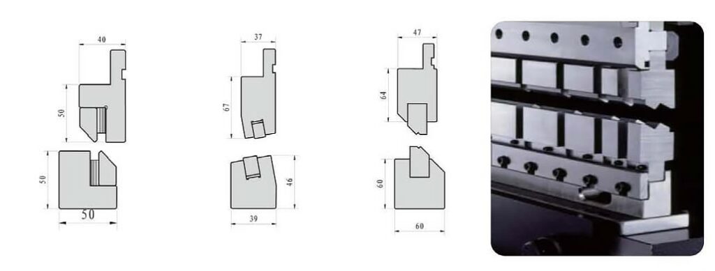
The standard and segmented lengths of the upper die for press brake tooling designed by Alliance Tooling are compatible with the dimensions of mainstream press brakes on the market. The specific specifications are as follows:
(1) Standard lengths for upper die: 835mm, 515mm, 595mm, 415mm
Segmented lengths for upper die:
(2) Standard lengths for lower die: 835mm, 515mm, 595mm, 415mm
Segmented lengths for lower die:
Although the tooling is sold as a complete set, it can be divided into multiple segments to meet customer needs.
The custom bending die process typically involves gathering the following information:
A complete drawing of the bending part and a detailed local drawing of the bending section, including the bending radius, internal and external contour dimensions, and tolerance ranges; the material and thickness of the sheet metal being bent; quality requirements for the appearance of the bent product, such as indentations and scratches; the type and model of the mechanical equipment used during the bending process, including maximum processing pressure, worktable length, clamping methods for the upper and lower dies, and die-closing height; as well as any other special requirements.
Our technical team is dedicated to providing clients with consultation services, offering solutions, information, and technical support to address complex technical issues. Only by thoroughly understanding the clients’ needs can we deliver customized bending die solutions.
To address the issue of sliding friction between the workpiece and the die slot during the bending process with traditional bending molds, which leads to abrasions on the outer side, mold manufacturing enterprises have actively pursued the development of mark-free mold structures.
This innovative design aims to reduce or eliminate the marks created on workpieces during the bending process, especially on the outer surfaces. By employing various mark-free mold structures, the surface quality of the workpieces during bending has been improved, enhancing the overall appearance and texture of the products.
The first type is the roller-style mark-free lower die.

By replacing the radiused corners of the bending die slot with a roller structure, the roller turns as it is driven by the workpiece during bending. This results in rolling friction on the outer side of the workpiece, effectively reducing abrasion marks.
Additionally, rollers made from high-hardness materials significantly increase the mold’s lifespan, making it the most commonly used type of mark-free mold. This innovative design not only improves the surface quality of the products but also enhances the durability of the mold, significantly improving the efficiency of the bending process and the quality of the finished products.
The second type is the rotary flip plate-style mark-free lower die.

Its structure features symmetric left and right rotating flip plates instead of a fixed integral V-groove. During the bending process, the workpiece and the rotating flip plates do not slide relative to each other, thus completely eliminating marks and abrasions that might occur.
The rotary flip plate-style mark-free lower die has several advantages: a modular structure, precision manufacturing, high mold accuracy; it prevents the formation of traditional bending marks; it avoids damage to the mold when bending laser-cut plates; it achieves ultra-short edge bending; and it prevents deformation when bending near holes or slots.
Suitable for bending mirror-finish stainless steel, aluminum plates, and other aesthetically decorative plates that require high surface quality, the rotary flip plate-style lower die greatly optimizes the surface quality of bent products.
The third type is the polyurethane mark-free lower die.
This design involves the use of a polyurethane structure for the lower die of the bending machine. It can completely eliminate marks on the outer side of the workpiece, although it presents some challenges in controlling the bending angle. Hence, this structure is mainly suitable for bending scenarios where precision in bending dimensions is not critical.
Despite the challenges in controlling the bending angle, this mark-free design provides softer support for specific workpieces, effectively avoiding the creation of marks on the outer side and offering another solution for specific bending needs.