I. Manual bending of profiles and pipes
Due to the high bending resistance of profiles, they are not easy to bend, so they are usually bent manually using a heating method.
1. Flat steel annealing bend
Flat steel bending usually adopts the following steps and methods:
(1) Making the mold
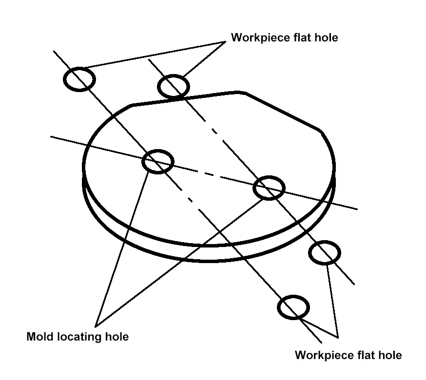
The mold for hot bending flat steel is generally made of steel plate, its thickness can be equal to or slightly thicker than the workpiece, and the mold’s arc diameter can be equal to the inner diameter of the workpiece. The mold for bending flat steel rings should not be made into a full circle, but about 2/3 of a full circle, as shown in Figure 4-15, which facilitates the placement and removal of the workpiece during bending.
The position and size of the holes for fixing the mold on the platform should be determined after the position of the mold on the platform is fixed, based on the position and size of the holes on the platform.
(2) Bending
Place one end of the heated flat steel against the mold, clamp it with a conical wedge and ram’s horn clamp, then insert the bender at the appropriate position to perform the bending, as shown in Figure 4-16. Each heating should not bend too long to avoid wrinkling the flat steel or causing material hardening due to low temperature. For larger part sizes, bending should be done in sections.
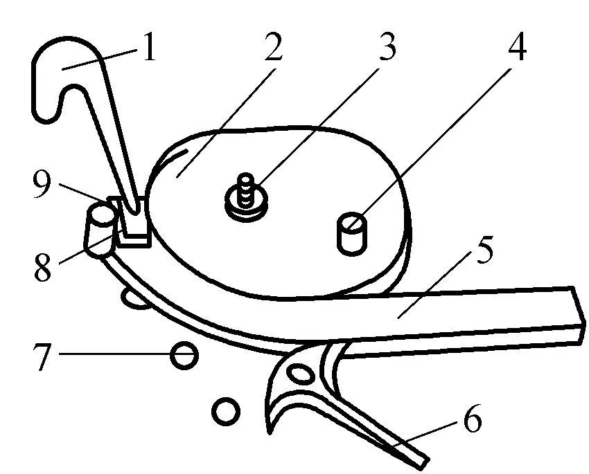
1—Ram’s horn clamp
2—Mold
3—Lock bolt
4—Tire wedge
5—Flat steel material
6—Bender
7—Platform hole
8—Tightening wedge
9—Spacer plate
(3) Leveling
After each annealing section, before the clamps are removed, use a flat hammer to level along the inside of the flat steel first, then along the outside, making the thickness on the inside and outside roughly equal, and to prevent significant deformation during the cooling process after demolding, as shown in Figure 4-17.

2. Angle steel bending
Angle steel bending also involves the processes of making molds, bending, and flattening.
The molds for angle steel bending are usually welded from steel plates, and their shapes depend on whether the bending is internal or external, as shown in Figure 4-18. Due to the asymmetrical cross-section of angle steel, the contraction of the inner and outer sides during cooling after bending is unequal, causing changes in the shape and size of the workpiece.
Therefore, the diameter of the mold should be appropriately increased when bending the angle steel externally; the diameter of the mold should be appropriately reduced when bending internally. The values for increasing or decreasing the diameter of the mold can be selected according to Table 4-1. Other requirements for angle steel bending molds are the same as those for flat steel bending molds.

a) Welded external angle steel bending mold
b) Welded internal angle steel bending mold
c) Mold made from a whole steel plate
Table 4-1 Angle steel hot bending mold diameter scaling sizes
| Internal bend/mm | Outer bend/mm | ||
| Template diameter | Tire tool diameter reduction size | Template diameter | Tire tool diameter enlargement size |
| <300 | <10 | <900 | 3~5 |
| 900 ~ 1400 | 10 ~15 | 900 ~1400 | 6 ~10 |
| 1500 ~10000 | 15 ~20 | 1500 ~10000 | 15 |
| >10000 | 25 | >10000 | 20 |
When bending angle steel, first quickly clamp one end of the heated angle steel on the tire tool, then bend while hammering the wrinkled part of the angle steel surface until the section of the angle steel to be bent is completely fitted to the tire tool, as shown in Figure 4-19. The bending of angle steel should also be carried out within the temperature range of steel hot bending.

a) Angle steel outer bend
b) Angle steel inner bend
After bending, it is also necessary to use a sledgehammer and a flat hammer to straighten it, so that the shape and dimensional accuracy of the workpiece meet the requirements.
3. Pipe Bending
Manual pipe bending is commonly used for bending single pieces or small batches of pipes, the steps and methods of manual pipe bending are as follows:
(1) Sand filling
Before manual bending, sand must be filled inside the pipe to prevent deformation of the pipe section. For non-ferrous metal pipes, substances with low melting points such as rosin and aluminum can be filled, and removed after bending. The sand should be pure, clean, dry, and generally have particles smaller than 2mm. The sand filled inside the pipe must be compact, therefore it is hammered while filling. The ends of the pipe are tightly plugged with wooden plugs or sealed with steel plates.
(2) Marking
For hot bending pipes, the length of the heating part must be marked. Generally, the midpoint position of the bending part is predetermined according to the drawing size, and from there, the bending length is measured to both sides of the pipe, plus the allowance for the pipe diameter, which is the length to be heated.
(3) Heating
Pipes can be heated using charcoal, gas, or heavy oil as fuel. Ordinary coal is not suitable for heating pipes, as coal contains a lot of sulfur, which can penetrate into the steel at high temperatures, deteriorating the quality of the steel. The heating temperature is about 950°C, and it is maintained for a period of time to bring the sand inside the pipe to the same temperature.
(4) Bending
Small diameter pipes can be bent on a semi-circular groove mold using a lever, while large diameter pipes can be bent on a platform using an electric winch. When there are multiple bends, start bending from the bend at the end of the pipe in sequence. During bending, water can be sprayed on the outer wall to prevent the pipe wall from becoming too thin. Spraying water for cooling can also adjust the degree of bending. If the inner side of the pipe is cooled with water spray, the metal on the inner side contracts, increasing the degree of bending, similarly, when the outer wall is sprayed with water, the degree of bending decreases.
II. Pipe Mechanical Heating Bending Forming
When bending pipes mechanically with heating, the methods include medium frequency heating and flame heating, which are introduced below respectively.
1. Medium Frequency Heating Bending
Medium frequency heating bending involves placing a medium frequency induction coil around the pipe blank, relying on medium frequency induction current to locally heat the blank to the required high temperature, then bending the heated part, and immediately spraying water to cool after bending, thus obtaining the required bent pipe parts.
Medium frequency heating bending requires specialized equipment for medium frequency induction electric heating bending machines. Depending on the method of applying bending torque by the bending machine, it is divided into pull bending and push bending types.
(1) Pull Bending Medium Frequency Bending
Figure 4-20 is a schematic diagram of pull bending medium frequency bending. The medium frequency induction coil 3 is located on the rotational centerline, passing medium frequency current through the coil, thereby generating an alternating magnetic field, and the induced current caused by the alternating magnetic field in the pipe blank heats the pipe blank.
The pipe blank 1 passes through the induction coil, one end is fixed on the rotating arm 5 with a chuck 4, and the other end is freely placed on the support roller or machine bed. Three support rollers 2 are used to determine the axial position of the pipe blank, to keep the pipe blank concentric with the induction coil and chuck.
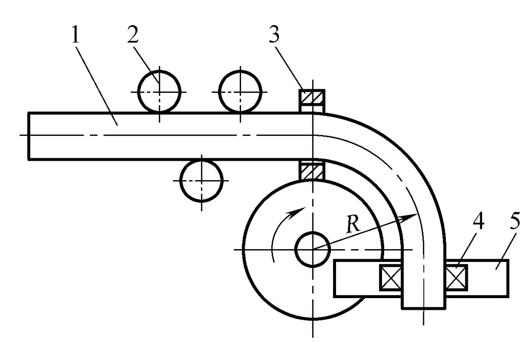
1—Pipe Blank
2—Support Roller
3—Induction Coil
4—Chuck
5—Swivel Arm
The pipe blank located behind the bending area is water-cooled by a ring device mounted on the induction coil after heating and bending, giving the bent pipe sufficient rigidity to maintain a perfectly circular cross-section. During operation, the induction coil locally heats the pipe blank to 800~1200°C, then the motor drives the swivel arm to rotate through the reducer, pulling and bending the pipe blank into shape.
Draw bending can bend smaller radii (minimum bending radius R=1.3D, while general cold bending machines are 1.5D), and the quality of the bent pipes is better.
The bending angle of the pipe can be accurately controlled by stopping the rotation of the swivel arm and the heating of the induction coil in time through limit switches. The bending radius is determined by the position of the chuck on the swivel arm, and the position of the chuck can be adjusted on the pipe. Heating temperature and heating zone width can be controlled by changing the current size, bending speed, water spray amount, and selecting the diameter of the induction coil. The current and the diameter of the induction coil are mainly selected according to the diameter of the pipe blank.
If the current is too high, the pipe blank will melt; if too low, the heating is insufficient. When the diameter of the induction coil is too large, the thermal efficiency is low; when too small, the gap between it and the pipe wall is small, adjustability is poor, and operation is inconvenient. When the bending radius is large, the deformation is small, and the bending speed can be faster. Conversely, the bending speed should be slower; otherwise, the outer wall thickness reduces significantly.
The bending radius obtained during medium frequency bending in draw bending is relatively uniform, and the adjustment is convenient, the bending angle can reach 180°, but the outer wall thickness is somewhat reduced.
(2) Push Bending
Figure 4-21 shows bending using medium frequency heating, with a schematic diagram of medium frequency heating bending. The pipe blank 2 is supported by the support rollers 3. By using the thrust plate 1 at the end of the pipe blank, an axial thrust F is applied to the pipe blank, thereby bending it into shape.
The bending radius is determined by the position of the top roller 5 or the position of the chuck 6 on the swing arm 7. Obviously, when bending pipes using the push bending method, the thinning of the outer wall thickness of the bent pipe blank is small, and because the high temperature zone is relatively narrow, it prevents the pipe wall from losing stability and the inner wall from wrinkling.
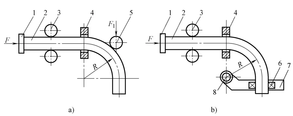
1—Thrust plate
2—Pipe blank
3—Support rollers
4—Induction coil
5—Top roller
6—Chuck
7—Swing arm
8-axis
The push bending method shown in Figure 4-21a can bend any radius, with minimal thinning of the outer wall of the tube, but it is difficult to ensure the bending radius at the start of the bend and adjustments are difficult. The push bending method in Figure 4-21b produces a uniform bending radius and is easy to adjust, with a typical bending angle of ≤90°, but the bending radius is limited by the adjustment range of the swing arm.
In summary, medium frequency induction bending has the following characteristics:
1) Cold bending of large diameter thick-walled tubes requires a large cold bending machine, occupies a large area, is costly, and also requires expensive molds. However, medium frequency induction bending does not require molds, just different pipe diameters and corresponding induction coils. But medium frequency induction units consume a lot of electricity and the equipment investment is also large.
2) Medium frequency induction heating is rapid, with high thermal efficiency, and the surface of the bent tube does not produce oxide scale.
3) The quality of the bent tube is good, with better roundness and less thinning of the wall thickness compared to cold bending. The bending radius is easy to adjust and highly adaptable. Especially suitable for bending single or small batches of large diameter pipes, as no molds are needed, thus manufacturing costs are low.
It should also be noted that since medium frequency bent tubes are immediately water-cooled after heating and bending, the impact should be considered when bending steel tubes prone to cracking by quenching using this method.
Flame heating bending
The principle of flame heating bending is the same as that of medium frequency induction bending, using a flame heating coil to replace the medium frequency induction coil to heat the billet, eliminating the need for a medium frequency induction unit.
The structure of the flame bending machine is simple, the cost is lower, maintenance is easy, and it can ensure good quality of the bent tubes, thus it has gained certain promotion and use in production. However, since the thermal efficiency of flame heating is not high, it is only suitable for bending thin-walled tubes.
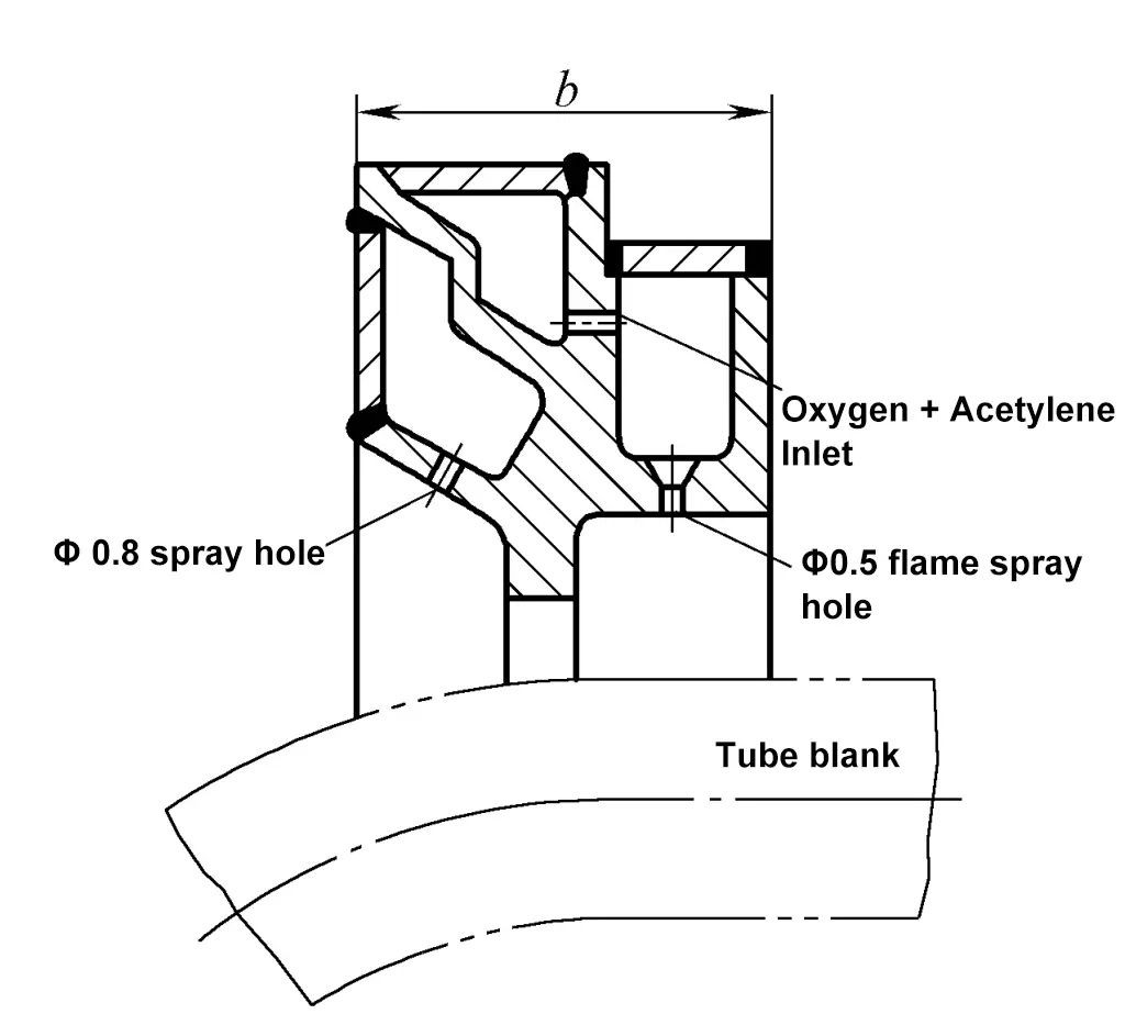
The flame heating ring is shown in Figure 4-22. It uses a mixture of oxygen and acetylene as fuel, generally with acetylene pressure at 0.05~0.1MPa and oxygen pressure about 0.5~10MPa. The diameter of the heating ring should match the outer diameter of the tube blank, and the usual distance between the flame nozzle ring and the tube wall is 13~15mm.
The inner circumference of the heating ring has a row of flame nozzles, with the nozzle diameter being about φ0.5mm, and the spacing between the holes is 4~5mm, evenly distributed. On the circumference of the heating ring facing away from the direction of the bent pipe, there are water spray holes, with the diameter of the spray holes being about φ0.8~1mm, and the spacing between the holes is about 10mm.
