Profile Bending: Top 4 Methods Explained
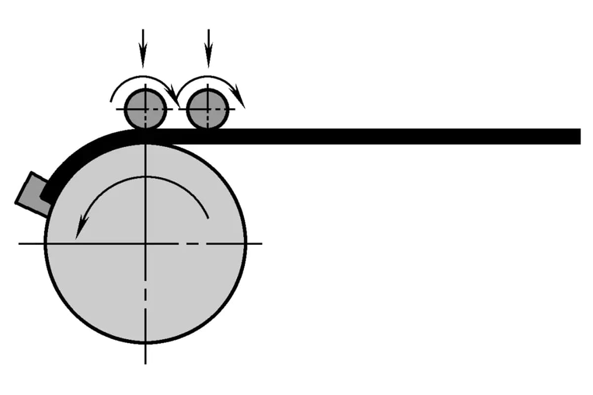
How do engineers bend profiles into intricate shapes with precision? This article explores four primary methods: press bending, roll bending,…
Why do profiles wrinkle, warp, or twist during bending? This article delves into the complexities of profile bending, highlighting common issues such as wrinkling, sectional distortion, and wall thickness reduction. It also offers practical solutions, including the use of core rods, fillers, and tension application, to mitigate these problems. By understanding these techniques, you can ensure higher quality in profile bending processes, reducing defects and improving overall efficiency. Ready to enhance your bending techniques? This article provides the insights you need.
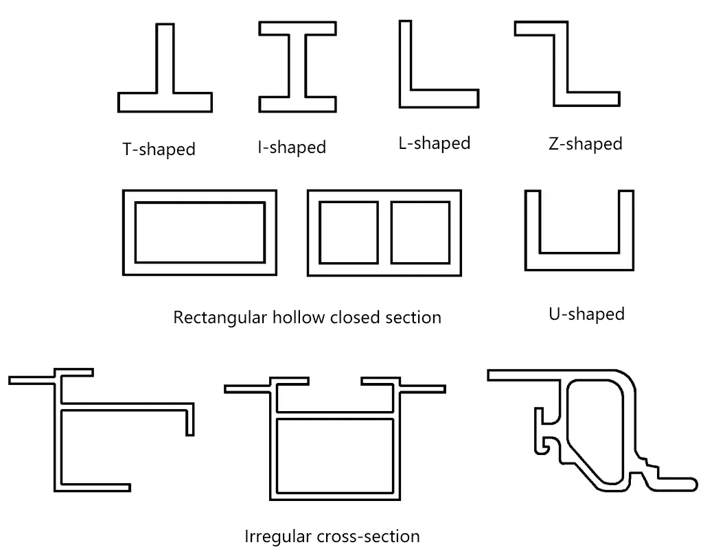
Compared with sheet metal, an important feature of profiles is their variety of cross-sectional shapes, as shown in Figure 1. Bending forming of profiles is different from that of sheet metal. Due to their specific cross-sectional shapes, many special quality issues often arise, such as cross-sectional distortion, inner side wrinkling, twisting, etc.
When the profile section is relatively high and the relative bending radius is small, and the process parameters are not set reasonably, wrinkling phenomena may occur on the inner edge or web of the profile after bending forming. The reason for the wrinkling is that during the bending process, the part below the neutral layer is subjected to longitudinal compressive stress. When the compressive stress is too large, or the compressed part lacks effective support, longitudinal wrinkling is likely to occur.
In stretch bending forming, if a certain amount of tension is applied to the profile while bending, wrinkling can be avoided; applying additional tension after bending also has a certain wrinkle-removing effect. Additionally, using limit or wrinkle-preventing grooves on the mold, or employing core rods for filling, are measures that can prevent wrinkling.
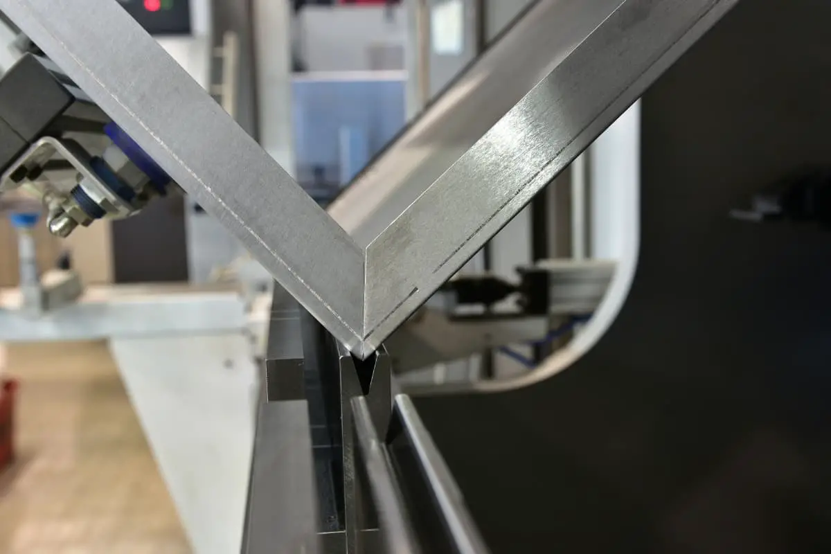
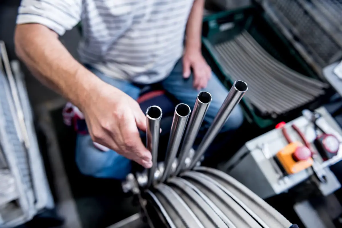
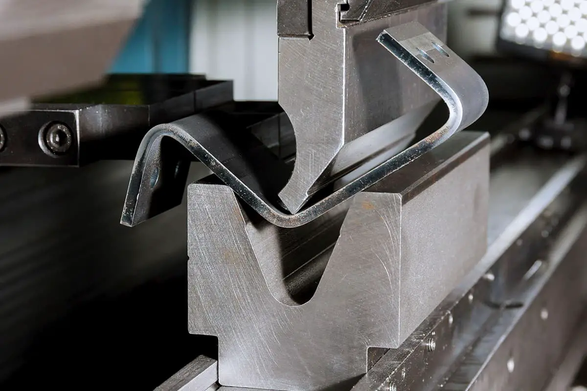
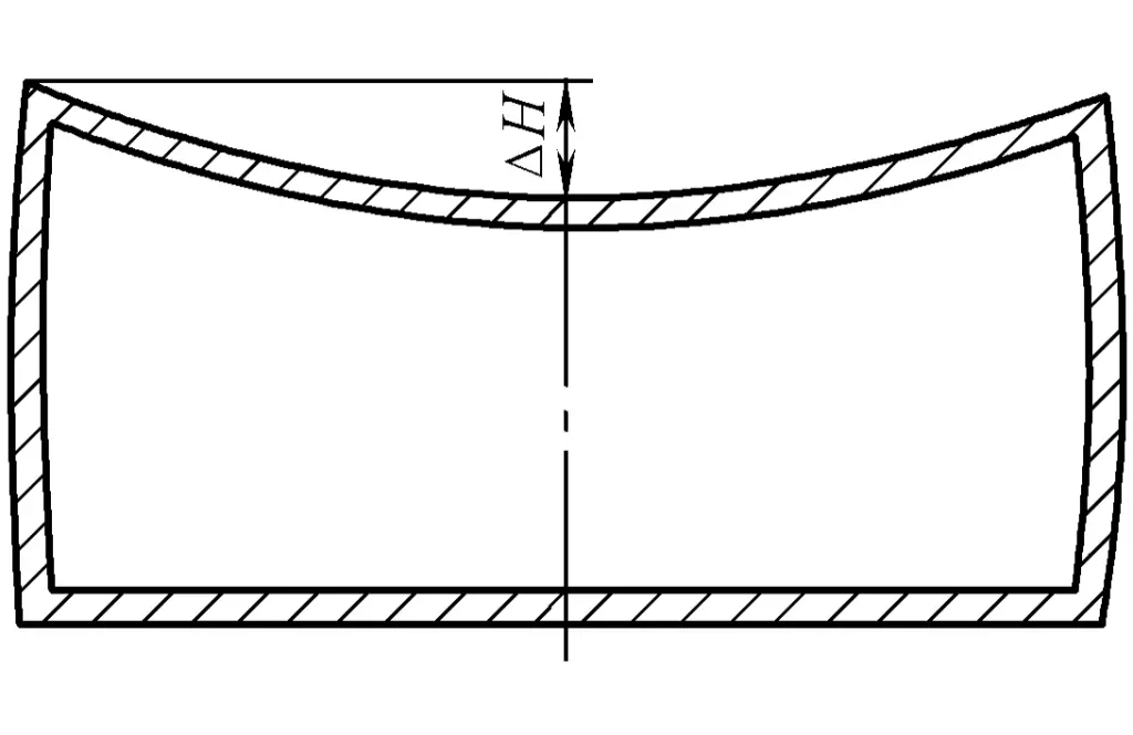
Sectional distortion is a problem that is difficult to avoid in profile bending forming. The deformation resistance of a profile section is closely related to the shape of the profile section. During the bending of closed-section profiles, when the web width is large, the wall thickness is thin, and there is no support inside or the support is weak, phenomena such as upper edge collapse can easily occur, causing sectional distortion of the profile, as shown in Figures 2 and 3. Similar phenomena occur during the bending of profiles with other sectional shapes.
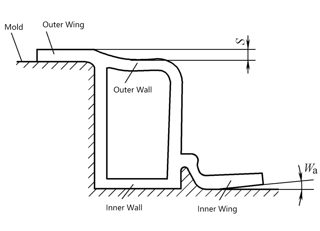
The occurrence of sectional distortion is very difficult to control, and it also makes the control of springback more complicated.
Currently, the methods to eliminate or reduce sectional distortion include, first, determining the profile section shape based on the manufacturability of the profile parts structure; second, supporting the profile during production (adding a core rod or filler).
To reduce sectional distortion, the first consideration should be the structural manufacturability of the profile parts, which is the most economical method. The main approaches are as follows (see Figure 4):
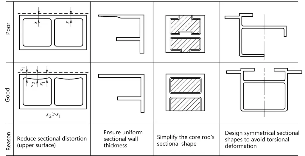
There are a variety of profile specifications. For structures with no special requirements, priority should be given to profiles with good formability, simple cross-sectional shapes, and symmetry, such as angle profiles, T-shaped profiles, rectangular hollow section profiles, arch-shaped profiles, etc.; the inner surface of the profile should be as smooth as possible to facilitate the insertion and removal of core rods and other fillers; the radius of the inner corner of the closed section profile should be designed as large as possible: the profile section should be as symmetrical as possible to prevent torsional deformation during bending.
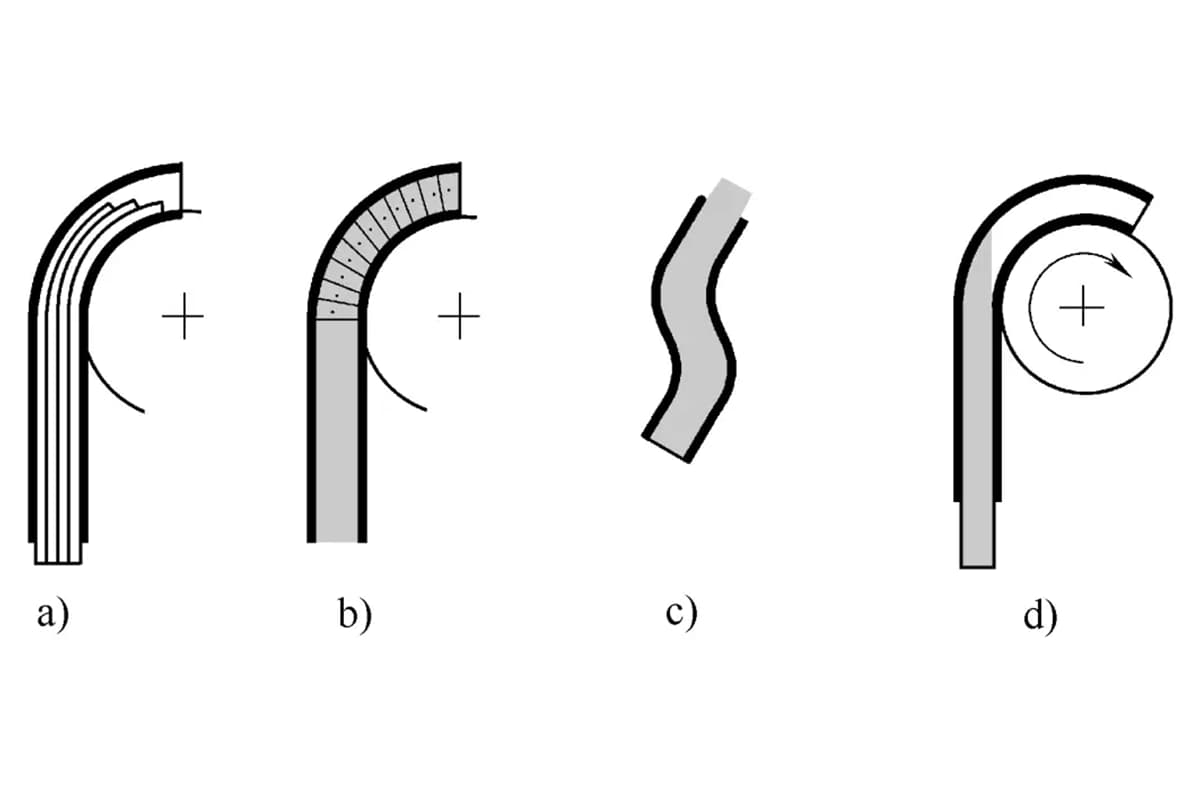
Inserting a core rod (laminated board, thin steel plate) or filler inside the profile can effectively prevent section distortion. The core rod has the same or similar shape as the undeformed inner surface of the profile, is inserted inside the profile before deformation, bends with the profile, or supports the bending part of the profile, and is pulled out from inside the profile after forming. Common core rod forms:
(1) Laminated core rod, as shown in Figure 5a, can be made of thin steel plates or materials such as PVC (Polyvinyl Chloride), Nylon, etc., and is widely used in two-dimensional bending. Thin plates are stacked together, placed inside the profile, bend with the profile, layers can slide relative to each other during bending, and because each layer is very thin, during bending, each layer of material is in an elastic deformation state.
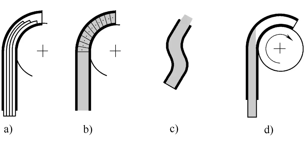
a) Laminated core rod
b) Linked core rod
c) Plastic core rod
d) Rigid core rod
Due to the existence of a certain gap between the core rod and the inner wall of the profile, the amount of profile cross-section distortion is affected by the size of the gap. The disadvantage of this type of core rod is that it is not easy to pull out due to the tight compression between the inner wall of the profile and the core rod after bending. Moreover, the work efficiency is lower during the production process.
(2) Link-type core rod, as shown in Figure 5b. The core rod is made up of many linked units, each chain unit’s shape is similar to the inner wall of the profile, and the core rod can deform with the bending of the profile. The effect of reducing cross-section distortion is very obvious. The disadvantage is that it is difficult to manufacture and costly.
(3) Plastic core rod, made of plastics such as polyethylene, has good sliding performance, making it easy to insert and pull out. It is in an elastic bending state during bending, as shown in Figure 5c. The disadvantage of the plastic core rod is that its elastic modulus and hardness are relatively low, which results in less constraint on the distortion of the profile cross-section, especially when the bending radius is small. In addition, the service life of this type of polymer material is short.
(4) Rigid core rod, as shown in Figure 5d. It does not bend with the profile, similar to the core rod used in bending formation with tubes. The metal rigid core rod is inserted into the inner cavity of the profile to the part where bending deformation occurs, providing rigid support to the upper belly plate of the profile during bending, effectively preventing the occurrence of cross-section distortion. This type of core rod is suitable for bending of constant curvature profiles.
In addition to adding a core rod, for closed-section profiles, some easily removable materials can also be filled to support the inner wall of the profile, as shown in Figure 6, this method is simple and easy to implement.
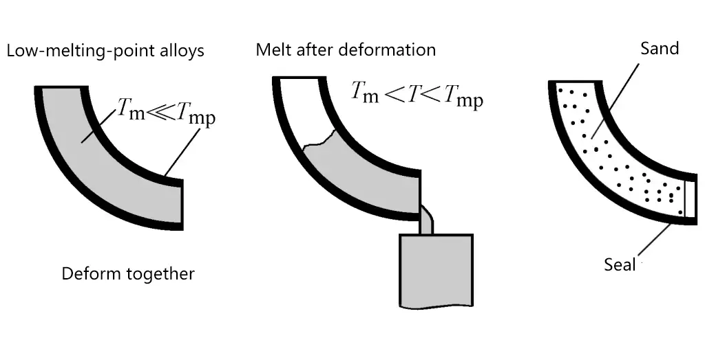
The most commonly used filler materials, such as low melting point alloys and wet sand. For filling with low melting point alloys, the interior of the profile is filled with low melting point alloy before bending, and after bending, it is heated to melt and flow out the alloy. The disadvantage of this method is that low melting point alloys are generally soft, providing weak support during the bending of the profile. If sand is used, the effect would be even worse, and it requires more manual labor, resulting in low efficiency.
Injecting liquid into the interior of closed section profiles can also reduce section distortion. Controlling the pressure of the liquid during bending forming has a significant effect on reducing distortion, but the downside is the need to increase pressurization and sealing devices.
The magnitude of the pressure depends on the material of the profile, the shape and size of the section, and the degree of bending. Practice has shown that the pressure does not have to be very high to have a noticeable effect; too high pressure can cause reverse bulging. Not only liquids but also gases can be filled to reduce section distortion.
When the bending radius is too small, or additional tangential tensile force is added to reduce springback and prevent wrinkling on the inner wall, there is a greater tensile stress on the section, especially on the outer wall, which causes excessive thinning of the outer wall thickness, and even rupture.
When the section height of the profile is relatively large and the bending radius is small, the thinning phenomenon is more serious. In the process of profile bending forming, excessive thinning or even rupture of the outer wall is one of the manifestations of the limits of profile bending forming.
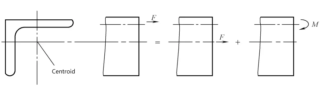
For profiles with asymmetric section shapes, in addition to common problems such as rupture, wrinkling, springback, and section distortion during forming, warping and twisting may also occur. Therefore, when stretching and bending profiles, the pulling center of the clamp block should coincide with the centroid of the profile section to avoid additional bending moments causing longitudinal warping of the profile, as shown in Figure 7. When bending, the point of application of the bending force should also be as close as possible to the center of bending to avoid torsional deformation.