Comprehensive Guide to Sheet Metal Bending: Z and N Bending Techniques and Safety Precautions
Bending sheet metal can be a complex yet rewarding task, essential for creating precise components in various industries. However, without…
Profiles are widely used in automobiles, aircraft, chemical machinery, and various metal structures, mainly formed by bending methods. Currently, in production, the common profile bending methods include pressing, rolling, wrapping, and drawing.
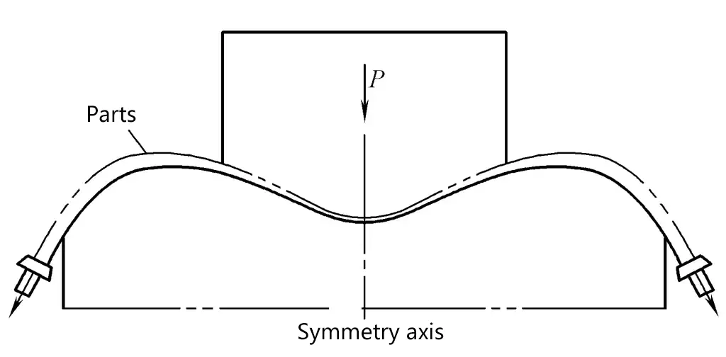
The process of bending profiles using bending dies on pressure processing machine tools such as presses and hydraulic presses is called press bending, as shown in Figure 1. To improve the quality of press-bent parts, concave dies with swinging devices are often used in press bending molds.
The biggest advantage of the press bending process is its simplicity and ease of operation, no need for special forming equipment, lower investment in equipment and molds, and high production efficiency. However, the accuracy of press-bent parts is generally poor, serious collapse often occurs at the bending parts, and springback is not easy to control. This method is generally used for simple-shaped, short parts and flat bending of profiles with thicker walls, the bending angle should not be too large, usually not exceeding 120°.
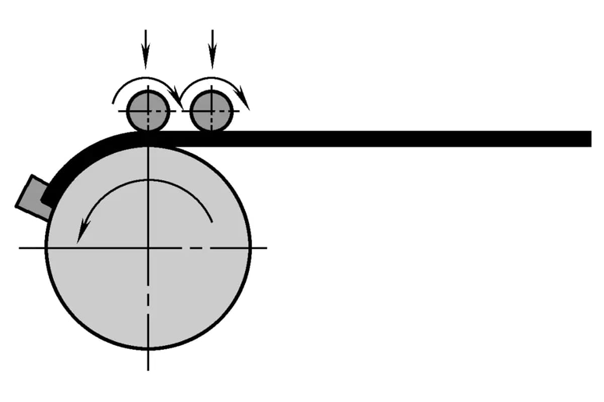
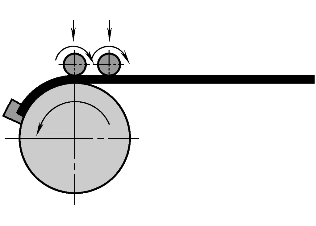
The forming process in which profiles are pushed forward and undergo bending deformation under the pressure and friction of rollers or roll shafts is called roll bending. Roll bending is divided into three-roll bending, four-roll bending, and multi-roll bending according to the number and arrangement of rollers, as shown in Figure 2.
Taking three-roll bending as an example, the profile is placed between the bending rollers, the driving roller pushes the profile forward, and the bending torque can vary with the distance between the rollers. The radius of curvature of the profile mainly depends on the vertical center distance between the upper roller and the two lower rollers and the horizontal distance between the two lower rollers.
Roll bending is versatile, and the amount of springback can be compensated by adjusting the position of the bending rollers sequentially. Four-roll bending can improve the accuracy of the profile’s cross-sectional shape because it can support the lower part of the profile.
Roll bending is suitable for forming profile parts with a larger radius of curvature and simple cross-sectional shapes, especially for forming profiles with equal curvature and symmetrical cross-sections. The advantage of roll bending is the simplicity of the equipment. The disadvantage is that the ends of the profile cannot be bent, and in addition, the workpiece lacks reliable support during forming, the inner wall is prone to wrinkling and instability, and the cross-section is prone to distortion; when bending asymmetric cross-section profiles, it is easy to twist and deform in the bending plane.
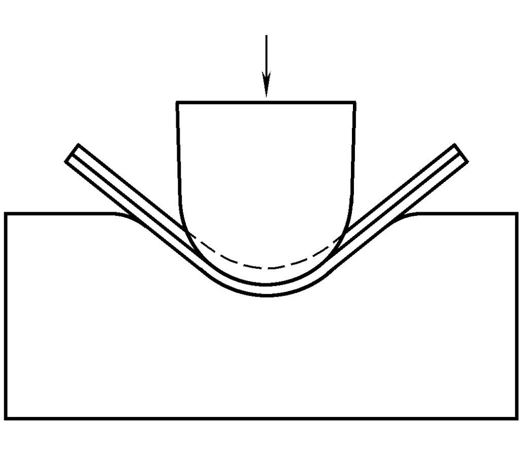
Wrap bending refers to the process of pressing the profile with a side press wheel or block, and gradually bending it around the bending mold as shown in Figure 3. The profile is clamped by the clamping slider on the rotatable bending mold, and the bending of the profile is achieved under the joint action of the mold rotation and the moving side press block.
When bending in this way, a tensile force can be applied to the tail of the profile, becoming bending under the action of tensile force. Controlling the axial tensile force can effectively avoid wrinkling on the inner wall and reduce the springback after forming, thus achieving bending forming of profiles with smaller radius of curvature. When applying guidance up and down in the direction of the vertical bending plane, three-dimensional bending forming can also be performed.
Another method of the wrap bending process is that the profile is clamped on the stationary bending mold by a clamping mold or clamping slider, and the profile is bent by rotating the turn mold or moving press block around the bending mold. This method has high production efficiency, and the bending angle can reach about 180°. However, the bending radius should not be too small, otherwise, wrinkles may occur on the inner surface of the bent part.
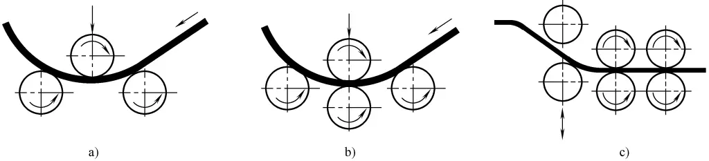
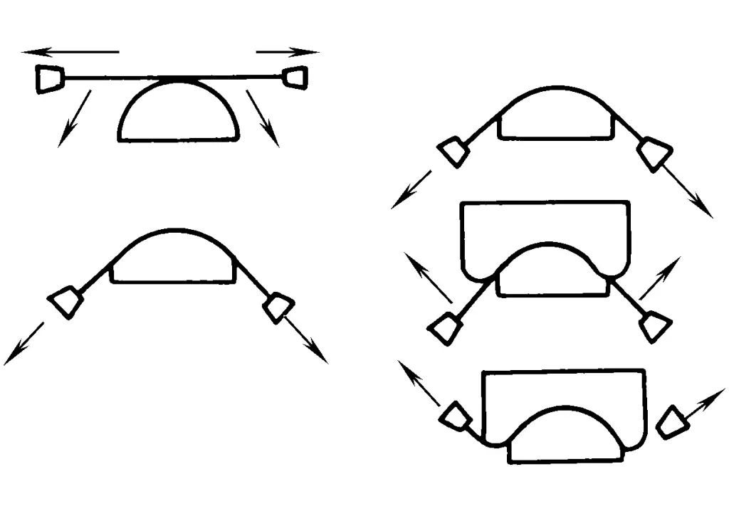
Stretch bending is a processing method that clamps both ends of the profile in a holding device (clamp) and bends it around the mold while applying tensile force. From the perspective of the equipment used, stretch bending forming can usually be divided into three types: straight-through table stretch bending forming, swing arm stretch bending forming, and turntable stretch bending forming, as shown in Figure 4.
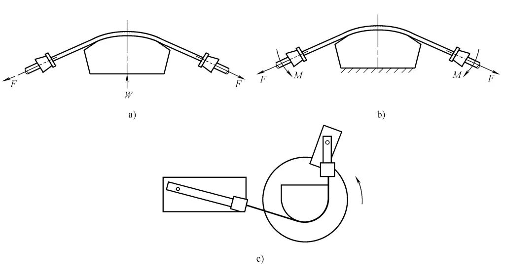
a) Straight-through table stretch bending
b) Swing arm stretch bending
c) Rotary table bending
The advantages of bending forming are small rebound of parts, low residual stress, and high production efficiency. It is most widely used in the bending processing of long profiles. The bending process is mostly used for the bending forming of open section profiles, but can also be used for the forming of closed section profiles. It can produce equal curvature bent parts as well as process variable curvature bent parts. The maximum bending angle of bending forming is generally less than 180°.
There are various bending methods according to different loading methods and sequences.
First, apply axial pre-tension to both ends of the profile, then apply bending moment under tension until it conforms to the mold.
First, apply bending moment to the profile to make it bend until it conforms to the mold, then apply axial supplementary tension.
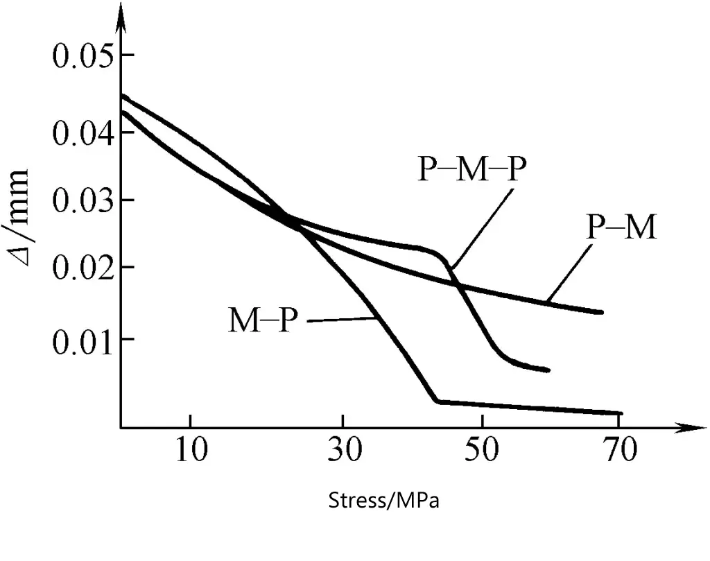
This method is most commonly used. First, apply axial pre-tension to both ends of the profile, then apply bending moment under tension until it conforms to the mold, and finally apply axial supplementary tension.
The purpose of pre-tensioning is to eliminate the initial torsional deformation of the profile in its supply state and to produce a certain initial tensile deformation, which can prevent the instability and wrinkling of the inner web of the profile during bending. The purpose of additional tensioning is to further reduce springback and improve forming accuracy.
The comparison of springback after unloading for three types of bending is shown in Figure 5, where
Δ =1 – R/R’
where
Under the premise of satisfying the precision of stretch bending forming, the amount of stretching of the profile should be as small as possible. Based on the relative bending radius and the size of the bending angle of the profile parts, determine the number of stretch bending operations and the amount of stretching for each operation.
Single stretch bending
Single stretch bending is suitable for stretch bending of medium and small-sized profile parts with small deformation. The minimum relative bending radius for typical aluminum alloy profiles in single stretch bending is shown in Table 1. The additional stretching rate for single stretch bending is shown in Table 2.
Table 1 Minimum relative bending radius for initial bending of 2024O, 7075O
| Bending angle α/(°) | 30 | 60 | 90 | 120 | 150 | 180~220 | 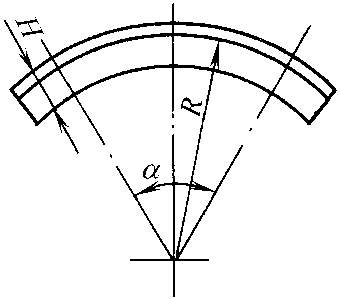 |
| Relative bending radius R/H | 10 | 15 | 23 | 27 | 34 | 38 |
Table 2 Initial bending stretch ratio A (%)
| R/ H | Material | ≥100 | 75 | 50 | 40 | 35 | 30 | 24 |
| α (90°) | 2024 | 3 | 3.2 | 3.8 | 4.2 | 4.5 | 4.9 | 5.6 |
| 7075 | 1.5 | 2.6 | 2.8 | 3 | 3.1 | 3.3 | 4.4 | |
| α (120°) | 2024 | 3.5 | 3.9 | 4.4 | 4.8 | 5.2 | 5.6 | |
| 7075 | 3 | 3.2 | 3.4 | 3.6 | 3.7 | 3.9 | ||
| α (150°) | 2024 | 4.1 | 4.4 | 5 | 5.5 | 5.8 | ||
| 7075 | 3.6 | 3.7 | 4 | 4.2 | 4.4 | |||
| α/(above 180°) | 2024 | 4.7 | 5 | 5.7 | 6.1 | |||
| 7075 | 4.2 | 4.3 | 4.6 | 4.8 |
Secondary bending
For aluminum alloy profiles, if the part’s relative bending radius is small, or there are higher requirements for the precision and surface quality of the part, or if the stiffness of the profile part is large, a reasonable manufacturing method is to use the same mold to bend twice. The first bending uses annealed profile raw materials, loaded in a “stretch then bend” manner, pre-stretched by about 1%, and then bent. The raw material is removed immediately after fitting the mold, and then sent for quenching.
In the newly quenched state, the second bending is formed by a “bend then stretch” loading method. At this time, the pre-formed part is first bent, and after fitting the mold, tension is applied. At the end of the second bending, the elongation of the material near the clamp can be controlled within the range of 1.5% to 3%. After two bendings, most parts significantly reduce the amount of springback, and can be delivered for inspection after minimal or even no manual rectification.
Secondary bending has the advantages of high accuracy, minimal manual rectification, and lower residual stress. The second bending after quenching must be completed within the new quenching incubation period of the material. To extend the incubation period after quenching, the newly quenched parts should be placed in refrigeration equipment. The stretch ratio after quenching is shown in Table 3.
Table 3 Elongation A (%) after quenching of 2024, 7075
| R/ H | 30 – 15 | 10 | 8 | 6 | 5 |
| α (90°) | 1.3 | 1.7 | 1.8 | 2 | 2.4 |
| α (120°) | 1.4 | 1.8 | 2 | 2.2 | 2.5 |
| α (150°) | 1.5 | 1.9 | 2.1 | 2.3 | 2.6 |
| α / (180°) | 1.6 | 2 | 2.2 | 2.4 | 2.8 |
The raw material length of bent parts can be calculated by the following formula
LM =0.99(L+2A)+2B
Where in the formula
Can be implemented on a cantilever bending machine or a turntable bending machine. When implemented on a cantilever bending machine, it is usually divided into two situations: bending without a side pressure device and bending with a side pressure device, as shown in Figure 6 and Figure 7 respectively.
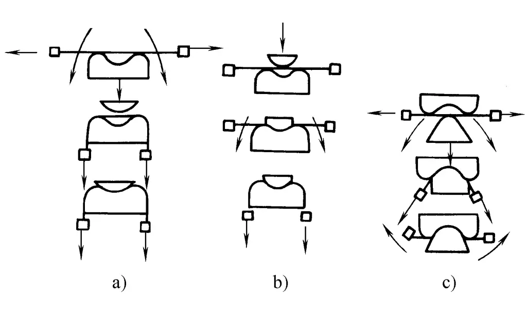
The typical process flow for bending without a side pressure device is to first pull out the first curvature, then install the reverse bending mold, reverse to form the second curvature, and finally pull again. There are three typical methods for bending with a side pressure device:
1) Pull first and then bend, followed by bending with the side pressure cylinder pressing against the convex mold, and finally pull again, as shown in Figure 7a. This method can only be used for parts with a small middle indentation.
2) Pre-pull first, bend with the side pressure cylinder pressing against the auxiliary convex mold, then bend again with the bending mold, and finally pull again, as shown in Figure 7b.
3) Pull first and then bend, the concave mold is pressed by the side pressure cylinder to hold the material, then bend according to the concave mold (reverse the cantilever or flip the part), and finally pull again, as shown in Figure 7c.
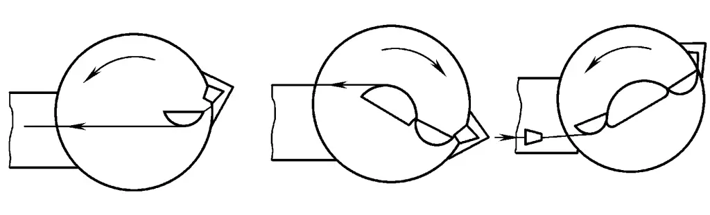
The typical process flow on a turntable bending machine is to complete the bending of parts with reverse curvature in separate steps through the forward and reverse rotation of the worktable, as shown in Figure 8.
For parts with changing profile section angles, the following measures can be taken according to the size of the angle change:
1) If the angle change is less than 3°, it can be pulled out directly while bending. To ensure the angle finally meets the technical requirements, a certain amount of manual correction can be performed after bending.
2) If the angle change exceeds 3°, to ensure the quality of the bending forming and reduce the amount of manual angle correction, a bevel can be prefabricated before bending according to its different angle changes; considering that the angle will change within a certain range during the bending process, the prefabricated bevel should be selected according to Table 4 for different types of parts. To make the part angle match the bending mold, the part can be adjusted by tapping the mold before unloading at the end of bending.
Table 4 Selection of prefabricated bevels before bending
| Bending form | Edge in | Edge out | ||
| Part bevel form | Open bevel | Closed bevel | Open bevel | Closed bevel |
| Pre-fabricated angle deviation direction | Too small | Too large | Too large | Too small |
3) On a turret type bending machine, it is possible to produce part bevels while bending, with an accuracy of up to ±30’.
General profile bending is carried out under constant cross-section and thickness, but for the following types of variable thickness profiles, bending can also be performed by taking necessary measures:
1) A profile with a uniformly increasing cross-section from small to large can be bent on a turntable bending machine. Start bending from the smaller cross-section end, initially using a smaller pulling force, and gradually increase the pulling force as the size of the cross-section increases until the final shape is formed.
2) Uniformly thickened “S” shaped parts. The paired combination bending method can be used, and the end with the smaller cross-section size is used as the combination end, as shown in Figure 9.