Punching of Tubular and Profiled Materials: Ultimate Guide
What if there was a way to enhance production efficiency while maintaining superior quality in machining tubular materials? The article…

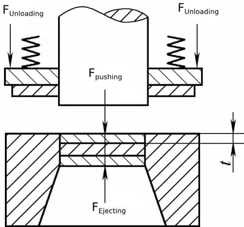
Punching force includes blanking force, stripping force, pushing force, and lifting force. Calculating the punching force is fundamental to selecting the right press, as shown in Figure 1.
Blanking Force
where:
Stripping Force, Pushing Force, Lifting Force
a) Stripping force is the force required to remove the material clamped on the punch, given by
Funloading = kunloading * F
b) Pushing force is the force needed to push the blank along the direction of blanking out of the die cavity, given by
Fpushing = n*kpushing*F
c) Ejecting force is the force required to lift the blank against the direction of blanking out of the die cavity, given by
Fejecting = kejecting * F
where:
The coefficients for unloading force, pushing force, and ejecting force are provided in Table 1.
Table 1: Ratios of Unloading Force, Feeding Force, Stripping Force to Punching Force
| Material Thickness/mm | Kunloading | Kpunching | Kejecting | |
| Steel | ≤0.1 | 0.065 – 0.075 | 0.1 | 0.14 |
| >0. 1 ~0.5 | 0.045 – 0.055 | 0.063 | 0.08 | |
| >0.5 ~2.5 | 0.04 – 0.05 | 0.055 | 0.06 | |
| >2.5 ~6.5 | 0.03 – 0.04 | 0.045 | 0.05 | |
| >6.5 | 0.02 – 0.03 | 0.025 | 0.03 | |
| Aluminum & aluminum alloys | 0.025 – 0.08 | 0. 03 ~ 0. 07 | ||
| Pure copper & brass | 0.02 – 0.06 | 0.03 ~ 0.09 | ||
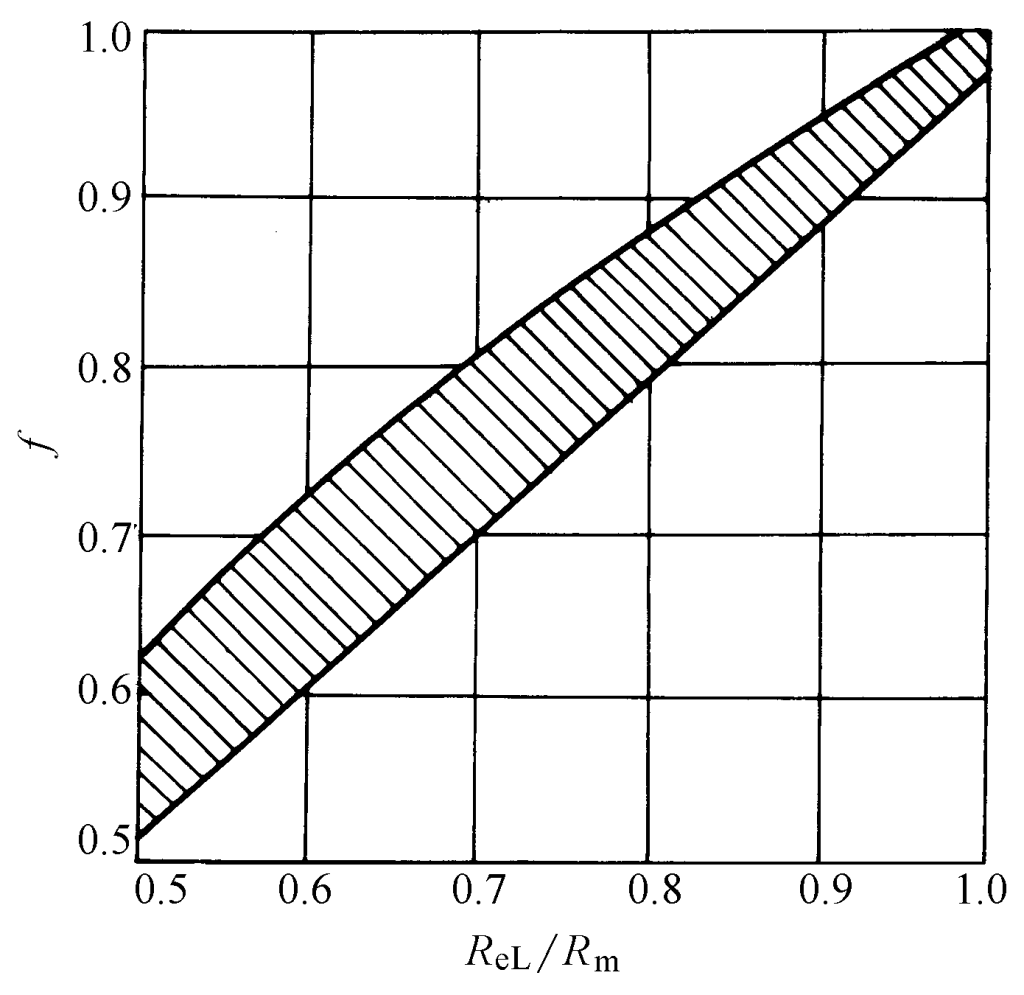
The magnitude of the punching force P depends on the total length of the inner and outer perimeters of the punching, the thickness of the material, and the tensile strength, and is related to the yield strength ratio of the material, which can be calculated by the following formula
P = fLtRm
The above calculation method was proposed by Timmerbeil. f=1-t’/t, where t’ is the depth at which the punch presses into the material when the maximum punching force occurs (i.e., the punching force P in the above formula), and it is related to the material’s yield strength ratio.
The punching force calculated using the above formula is quite consistent with reality and has been incorporated into the German standards. Additionally, the mechanical properties provided by the raw materials include the material’s tensile strength R m and lower yield strength R eL , and their ratio is used to obtain f from Figure 2-2-35, thereby calculating the punching force, which is convenient for use.
After the punching operation is completed, the punched workpiece (or scrap) undergoes radial elastic deformation and expands, while the hole on the scrap (or workpiece) undergoes radial elastic contraction. At the same time, both the workpiece and scrap attempt to recover their elastic curvature. The result of these two elastic recoveries causes the workpiece (or scrap) to get stuck in the die cavity, and the scrap (or workpiece) to clamp tightly onto the punch.
The force used to unload the workpiece (or scrap) from the punch is called the unloading force. The force used to push the workpiece (or scrap) out of the die cavity in the punching direction is called the pushing force. The force used to eject the workpiece (or scrap) from the entrance of the die cavity in the opposite direction of punching is called the ejecting force (see Figure 2-2-36). Clearly, these forces must be considered when selecting the press tonnage and designing the mold.
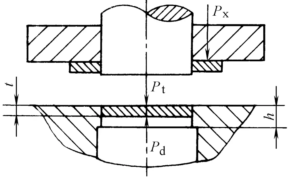
Many factors affect these forces, mainly including: the mechanical properties and thickness of the material, the shape and size of the workpiece, the clearance between molds, the size of the layout overlap, and lubrication conditions, etc. Due to the complex influence of these factors, it is difficult to calculate accurately. In production, the following empirical formulas are commonly used for calculation
Px =KxP
Pt =nKtP
Pd=KdP
Table 2-2-9 Values of coefficients K x , K t , K d
| Material and thickness / mm | Kx | Kt | Kd | |
| Steel | ≤0.1 | 0.065~0.075 | 0.1 | 0.14 |
| >0.1~0.5 | 0.045~0.055 | 0.065 | 0.08 | |
| >0.5~2.5 | 0.04~0.05 | 0.055 | 0.06 | |
| >2.5~6.5 | 0.03~0.04 | 0.045 | 0.05 | |
| >6.5 | 0.02~0.03 | 0.025 | 0.03 | |
| Aluminum, aluminum alloy | 0.025~0.08 | 0.03~0.07 | ||
| Pure copper, brass | 0.02~0.06 | 0.03~0.09 | ||
Note: K x should take the upper limit value when punching multiple holes, large flanges, and complex contours.
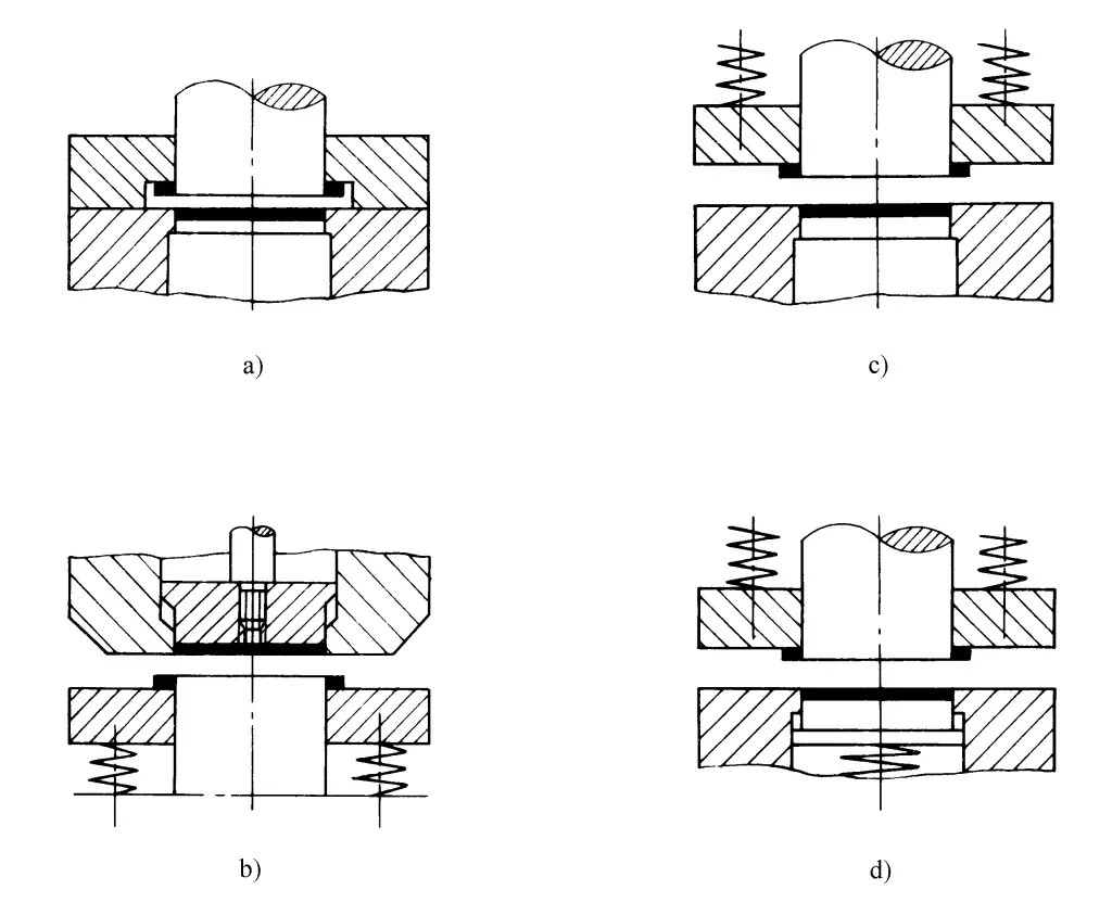
When selecting the tonnage of the press, whether these forces are considered in the total punching force depends on the different mold structure types (see Figure 2-2-37).
1) The total punching force using a rigid stripper plate (see Figure 2-2-37a) is
Pz=P+Pt
2) The total punching force using a rigid ejector, elastic stripper inverted mold (see Figure 2-2-37b) is
P z = P + P x
3) The total punching force using an elastic unloading plate (see Figure 2-2-37c) is
P z = P + P t + P x
4) The total punching force using elastic top parts and elastic unloading (see Figure 2-2-37d) is
P z = P + P d + P x
Clamping force P y is the mandatory constraint force on the sheet metal, an effective method to improve the quality of the workpiece cross-section and reduce bulging. The clamping force on the die surface is provided by an elastic movable clamping plate. The clamping force on the punch end face is provided by a movable back pressure plate. The magnitude of the clamping force can be approximately calculated by the following formula:
P y = (0.10 to 0.20)P
The coefficient value depends on the material properties, with higher values for hard materials or materials with a high work hardening coefficient, and lower values for soft materials.
Comparing P x , P d , and P y , P y is the largest. Therefore, when designing molds, if clamping is needed, just design the elastic clamping device according to P y , which can not only achieve clamping but also provide reliable, sufficient unloading force and top part force. If clamping is not needed, then design the corresponding unloading device and top part device according to P x and P d respectively.
Lateral force P c , on one hand, causes wear on the convex and concave sides of the mold, and on the other hand, when the punching line is not closed (such as single-sided punching or side blade punching), it makes the convex mold susceptible to unwanted bending deformation under lateral force, and even breakage. In such cases, it is necessary to design rear support to provide a lateral reaction force similar in magnitude and opposite in direction to P c , maintaining basic lateral force balance on the convex mold. Generally, lateral force P c can be approximately calculated by the following formula
P c = (0.30 to 0.38)P
When punching high-strength materials or thick, large-sized workpieces, if the required punching force exceeds the tonnage of the existing presses in the workshop, measures must be taken to reduce the punching force. Generally, the following methods are used:
The shear strength of the material significantly decreases when heated, thus effectively reducing the punching force. The downside of this method is that the material forms an oxide skin after heating, and the working conditions are poor due to the heating. Therefore, it is generally only suitable for thick plates or workpieces where surface quality and dimensional accuracy are not highly demanded.
Table 2-2-10 lists the shear strength of steel when heated. When calculating the heated punching force, τ b should be taken based on the actual stamping temperature. Due to heat dissipation, the stamping temperature is usually 150-200°C lower than the heating temperature. Additionally, the effects of thermal expansion and contraction on the dimensions of the workpiece, as well as the softening of the material during hot punching, should be considered, and the mold gap should be appropriately smaller than during cold punching.
Table 2-2-10 Shear strength of steel when heated
| Material grade | τ at the following temperature b / MPa | |||||
| 200°C | 500°C | 600°C | 700°C | 800°C | 900℃ | |
| Q195, Q215, 10, 15 | 360 | 320 | 200 | 110 | 60 | 30 |
| Q235, Q255, 20, 25 | 450 | 450 | 240 | 130 | 90 | 60 |
| Q275, 30, 35 | 530 | 520 | 330 | 160 | 90 | 70 |
| Q295, 40, 45, 50 | 600 | 580 | 380 | 190 | 90 | 70 |
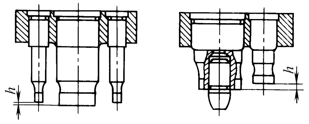
In multi-punch blanking, the punches are made at different heights in a step arrangement, which allows the punches to contact the material at different times, avoiding the simultaneous occurrence of maximum blanking force on each punch, thereby reducing the blanking force.
The calculation of the blanking force for step-arranged punches should be determined by the sum of the maximum blanking forces of punches at the same height.
The following principles should be considered when using step-arranged punches:
1) The difference in punch height h is related to the material’s tensile strength (see Table 2-2-11).
Table 2-2-11 Relationship between punch height difference h and material tensile strength
| Material tensile strength R m /MPa | h/mm |
| <200 | 0.8t |
| 200~500 | 0.6t |
| >500 | 0.4t |
Note: t is the material thickness.
2) The distribution of each step punch should pay attention to symmetry and proximity to the pressure center.
3) The first punch to start work should be the one with a guide pin at the end (see Figure 2-2-38), or make the larger punch longer and the smaller punch shorter, which can prevent the smaller punch from breaking or tilting due to the pressure of material flow. Moreover, making the smaller punch shorter improves its rigidity, prevents longitudinal instability, and enhances its service life.
When punching with a flat edge die, shearing occurs around the entire perimeter of the workpiece simultaneously, so the punching force is often very large when punching large and thick workpieces.
When using a bevel edge die for punching, similar to bevel shearing, the entire edge does not contact the workpiece perimeter simultaneously, but gradually punches the material, thus significantly reducing the punching force and reducing vibration and noise during punching.
When using a bevel edge for punching, to obtain a flat workpiece, the punch should have a flat edge, and the bevel should be on the die, so that the punched workpiece is flat and the scrap is bent (see Figures 2-2-39a, b, c). When punching holes, the die should have a flat edge, and the bevel should be on the punch, so that the punched holes are flat and the scrap is bent (see Figures 2-2-39d, e, f). When designing the bevel, it should be symmetrically arranged to avoid the die (or punch) experiencing unilateral lateral pressure during punching, causing misalignment and damaging the edge.
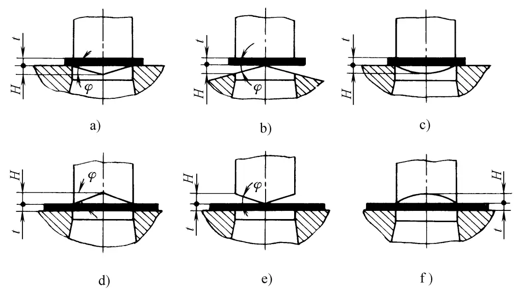
The degree of force reduction in bevel punching depends on the bevel angle φ (see Table 2-2-12).
Table 2-2-12 Bevel Parameters
| Material Thickness/mm | Bevel blade height H/mm | Bevel angle φ/(°) | K |
| <3 | 2t | <5 | 0.3~0.4 |
| 3 ~10 | t | <8 | 0.6~0.65 |
The punching force of each bevel blade is calculated by the following formula
Ps=KP
For large punching dies, when making a bevel die, the bevel should be made into a symmetrically arranged wavy form (see Figure 2-2-40).
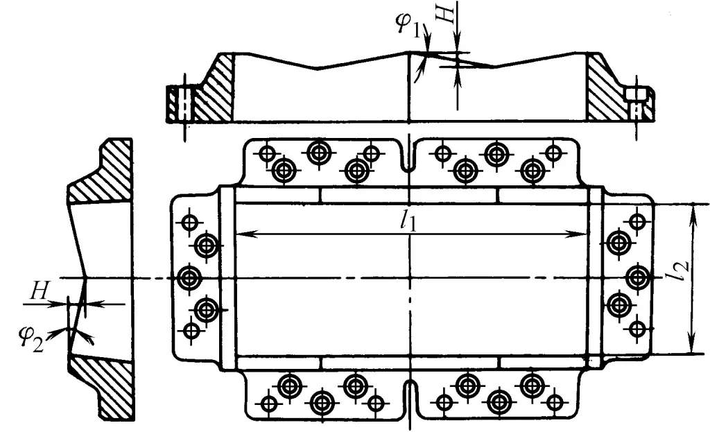
Although the bevel die reduces the punching force, it increases the difficulty of mold manufacturing and grinding, and the blade edge is also prone to wear, thus it is generally only used for large workpieces and thick plate punching.
The punching power of a flat blade die can be calculated by the following formula
W =(xPt)/1000
Table 2-2-13 Values of coefficient x
| Materials | Material thickness / mm | |||
| <1 | 1~2 | 2~4 | >4 | |
| Mild steel (τ b =250~350MPa) | 0.70~0.65 | 0.65~0.60 | 0.60~0.50 | 0.45~0.35 |
| Medium hardness steel (τ b =350~500MPa) | 0.60~0.55 | 0.55~0.50 | 0.50~0.42 | 0.40~0.30 |
| Hard steel (τ b =500~700MPa) | 0.45~0.40 | 0.40~0.35 | 0.35~0.30 | 0.30~0.15 |
| Aluminum, Copper (annealed) | 0.75~0.70 | 0.70~0.65 | 0.65~0.55 | 0.50~0.40 |
The punching power of the oblique blade die can be calculated by the following formula
W s = x 1 P s (t+ H)/1000
Where
When the stamping process involves simultaneous blanking force, feeding force, and ejecting force, the total stamping force F is calculated as follows: Total stamping force Ftotal = F + Funloading + Fpushing + Fejecting.
In this case, the tonnage of the press selected should be approximately 30% greater than Ftotal to provide the necessary margin.
When F, Funloading, Fpushing, and Fejecting do not occur simultaneously, Ftotal is calculated by only adding the forces present at the same instant.
In production, detailed calculations are typically performed for the punching force only, while the unloading force is estimated based on a fixed proportion of the punching force, plus the margin required for punching, totaling 50%.
Thus, the formula for calculating the tonnage of the press is:
Fpress = F × 150% = 1.5F