I. Perforation of the pipe wall
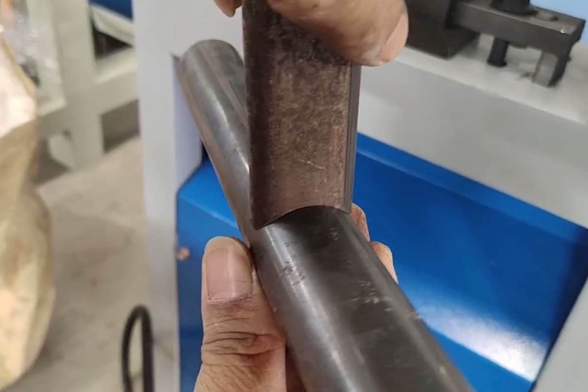
In mass production, the holes on pipe parts are processed by punching instead of drilling and milling, which has the advantages of high production efficiency, beautiful surface of the parts, and can meet the special needs of some products. At the same time, pipe punching does not require special equipment, and can be punched on a general press, with a simple mold structure, thus it can be included in the conventional production process.
Pipe punching is different from sheet punching. Since the sheet is a flat blank, the male and female dies apply force to the sheet during stamping, causing the material to separate, thus making the punching process easy to complete. However, the pipe is a hollow cylindrical blank, and during stamping, the male die contacts the curved surface of the pipe wall rather than a flat surface, therefore, special technological measures and structural forms need to be adopted when designing the mold.
Pipe wall punching molds can be divided into three types according to their structural features: with female die punching, without female die punching, and rubber mold punching.
1. With female die punching mold
When the pipe wall has a female die punching, according to the relationship between the movement direction of the male die during the mold operation and the movement direction of the press slider, it can be divided into vertical punching and horizontal punching.
Vertical punching means that the movement direction of the male die is the same as the movement direction of the press slider. It involves mounting the male die on the upper mold, which moves up and down with the press slider, while the female die is mounted on the cantilever bracket of the lower mold, allowing punching when the male die moves downward. Since the female die in this type of mold is cantilever-mounted, it is often referred to as a cantilever punching mold.
During horizontal punching, the movement direction of the male die is perpendicular to the movement direction of the press slider. Both the male and female dies are mounted on the lower mold, using a diagonal wedge mounted on the upper mold to push the slider with the male die on the lower mold to move horizontally, achieving the purpose of punching the pipe wall (multiple holes can be punched simultaneously).
Since this type of mold uses a diagonal wedge mechanism to drive the male die to move horizontally, it can be called a diagonal wedge type punching mold. Below are introductions to several typical mold structures.
(1) Cantilever punching mold
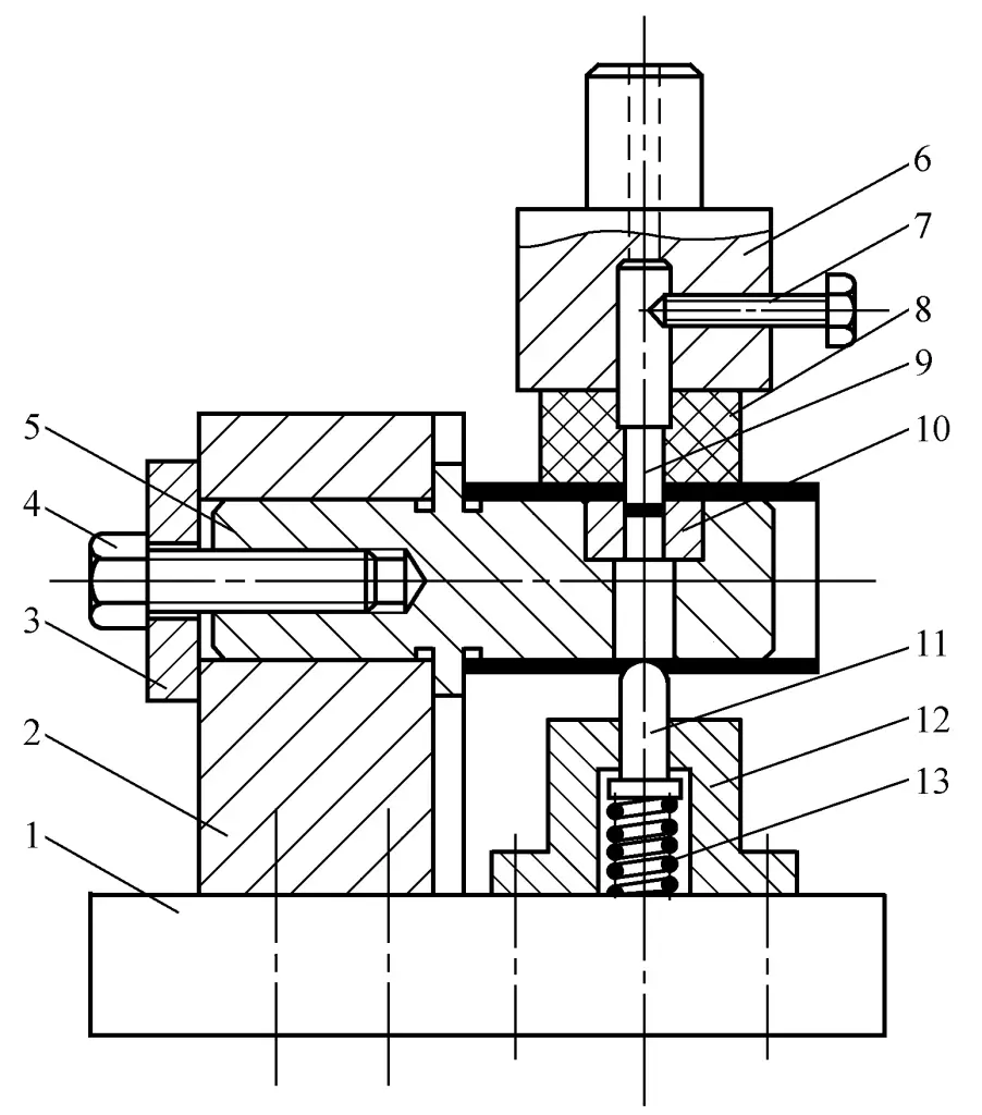
Figure 2-2-87 shows the structure of a cantilever single punch punching die. The die 10 is press-fitted on the die holder 5, which is mounted in the holder 2 and fastened by screws. The two holes on the wall of the tube are punched out in two strokes.
1—Lower die plate
2—Holder
3—Pressure plate
4,7—Screws
5—Die holder
6—Die handle
8—Rubber
9—Punch die
10—Concave mold
11—Positioning pin
12—Spring seat
13—Spring
After punching the first hole, rotate the tube blank 180°, and punch the second hole after the positioning pin 11 is inserted into the punched hole. The structure of this mold is simple and suitable for small batch or batch production. However, the disadvantage is that the cantilever bracket is under poor stress conditions, and when the punching force or force arm is large, the bending moment produced is large, so strength verification should be carried out.
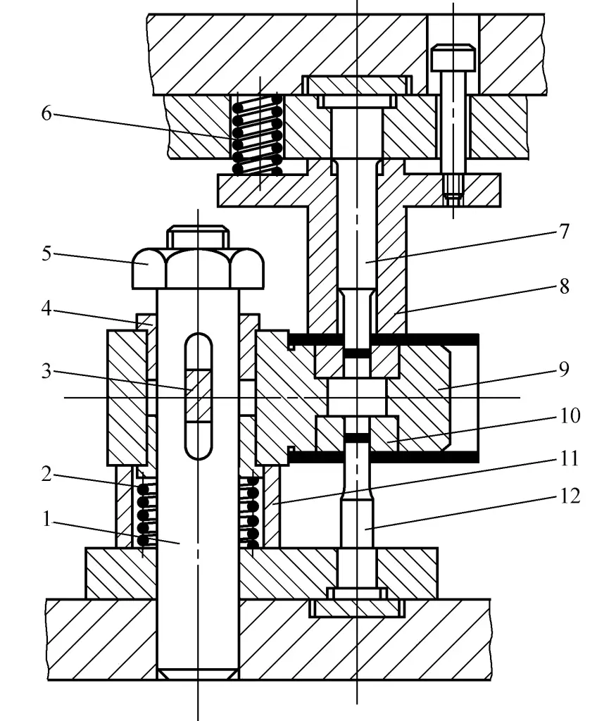
Figure 2-2-88 shows the structure diagram of a cantilever type counter-punching hole mold. The two convex molds 7, 12 are mounted on the upper and lower molds respectively, and the concave mold 10 is press-fitted on the concave mold bracket 9. The bracket is guided by the guide post 1 and can move up and down, and the slide key 3 is mounted on the bracket and slides along the slot of the guide post to ensure that the bracket does not rotate relative to the guide post.
1—Guide post
2, 6—Spring
3—Slide key
4—Liner
5—Nut
8—Discharge plate
9—Die holder
10—Concave mold
11—Limiter
This mold can punch two opposite holes on the tube wall in one stroke of the press. As the mold uses a simultaneous punching process and the holder is balanced in force, it can avoid the problem of insufficient strength caused by large bending moments during cantilevered single punching.
(2) Oblique wedge punching die
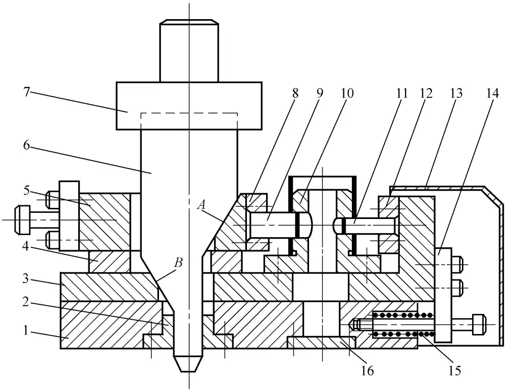
Figure 2-2-89 shows the structure of a single oblique wedge punching die. Its working principle is: when the oblique wedge 6 moves downward, it moves the upper slider 5 to the right by the inclined surface A, and the lower slider 3 to the left by the inclined surface B, then the left and right punches 9, 11 enter the die 10 simultaneously, punching two holes on the tube wall. As the oblique wedge moves upward, the upper and lower sliders are reset by the spring 15 (the reset spring for the upper slider is not shown in the figure). The punching scrap is then discharged through the scrap holes.
1—Lower die plate
2—Guide sleeve
3—Lower slider
4—Support plate
5—Upper slider
6—Inclined wedge
7—Die handle
8, 12—Punch fixing plate
9—Left punch
10—Concave mold
11—Right convex mold
13—Protective cover
14—Baffle
15—Spring
16—Cover plate
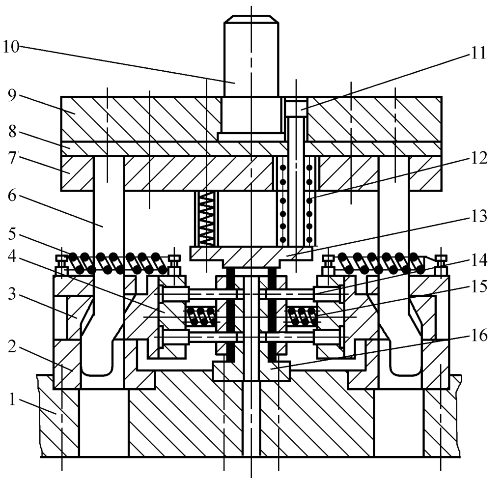
Figure 2-2-90 shows the structure of a double oblique wedge punching die. The mold uses two oblique wedges 6, and the mold structure is symmetrical left and right. In one stroke of the press, holes can be punched simultaneously on the left and right side walls of the tube. When the oblique wedge moves upward, the left and right sliders 3 are reset by the oblique wedge and auxiliary springs 5, 15. The punching waste then falls through the hole in the worktable of the press.
1—Lower die plate
2—Guide plate
3—Slider
4—Convex mold fixing plate
5, 12, 15—Spring
6—Inclined wedge
7—Fixed Plate
8—Spacer Plate
9—Upper Template
10—Mold Handle
11—Ejector Screw
13—Press Plate
14—Punch
16—Die
Compared to the cantilever punching die, the inclined wedge punching die has the following characteristics:
1) The left and right convex dies enter the concave die at the same time, the concave die works stably, and the strength of the concave die is more guaranteed.
2) The inclined wedge converts the vertical movement of the press slider into the horizontal movement of the convex die, so the alignment of the convex and concave dies is not affected by the guiding accuracy of the press slider.
3) The disadvantage is that the die has a larger plane size, and the manufacturing precision of the inclined wedge and slider, as well as the assembly precision of the convex and concave dies (to ensure alignment) are required to be high.
2. Punching die without concave die
Punching the tube wall without a concave die, that is, punching the tube wall with only the convex die without concave die support inside the tube. Obviously, when punching in a hollow state, if the pressure applied by the convex die on the tube wall exceeds the capacity the tube wall can withstand, the tube will be flattened, making the punching process impossible. To perform punching on the tube without a concave die, the primary condition is to maximize the pressure-bearing capacity (rigidity) of the tube.
Therefore, special measures must be taken in both the process and the die structure to meet this requirement and ensure that the punching process can proceed.
(1) Process characteristics
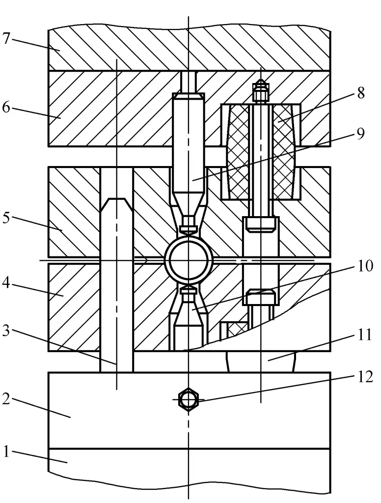
Figure 2-2-91 shows a simplified diagram of the tube double-hole punching die, which is symmetrically arranged above and below, and is one of the typical structures for tube punching without a concave die. When the die starts working, before the upper and lower convex dies 9 and 10 touch the tube wall, the upper and lower movable pressing plates 5 and 4 first press the tube, and then the upper and lower convex dies punch into the tube wall sequentially.
1—Lower die holder
2—Lower punch fixing plate
3—Guide post
4—Lower movable pressure plate
5—Upper movable pressure plate
6—Upper punch fixing plate
7—Upper die holder
8,11—Polyurethane rubber
9—Upper punch
10—Lower punch
12—Top thread
When the work is finished, the press slider returns, and the movable pressing plate unloads the pipe fitting, completing one punching process.
The punching process is shown in Figure 2-2-92. Since the tube material is always under compression before and during punching, this greatly enhances the stiffness of the tube material, preventing unstable deformation (flattening due to insufficient stiffness) during the punching process.

Therefore, during the tube punching process, the hole area of the tube wall is gradually pushed into the inner part of the tube wall by the punch, causing the material to bend elastically to plastic deformation, and finally resulting in fracture separation.
It can be seen that compared to punching with a die, tube punching without a die has the following characteristics:
1) When performing tube punching without a die, the primary condition is that all the tube material outside the punching area must be compressed before the start of punching, until the entire punching process is completed. Otherwise, the tube material will deform under the pressure of the punch, making the punching process impossible. Therefore, a pressing device must be set up on the mold to provide sufficient compressive force.
2) During tube punching without a die, since there is no die support, the elastic deformation process of the material is longer and the bending deformation is greater, thus forming a “dent” around the punched hole (see Figure 2-2-93). The size of the “dent” depends on the size of the tube material, type of tube material, punching size, mold structure, compressive force, etc. Therefore, tube punching without a die is only suitable for tube parts that allow a “dent” around the punched area.
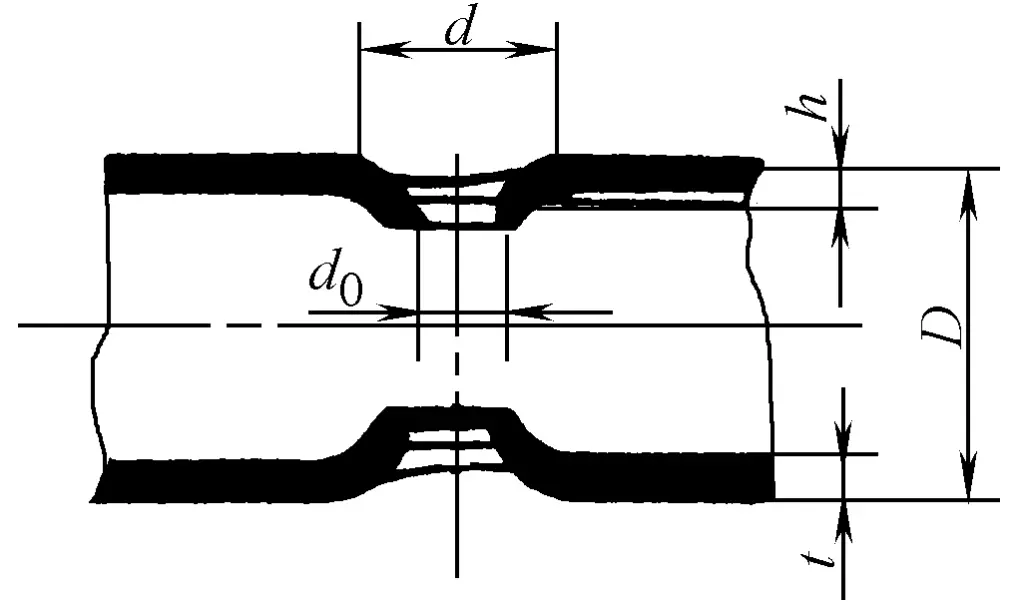
Table 2-2-42 lists the “dent” sizes formed in steel tubes with an outer diameter of ϕ30mm under the same compressive force but different materials, wall thicknesses, and punching diameters. As the table shows, the harder the material, the thicker the tube wall, and the smaller the punching diameter, the smaller the size of the “dent”; conversely, the larger the “dent” size.
Table 2-2-42 “Pit” Size Formed During Pipe Punching (Unit: mm)
| Steel Pipe Outer Diameter × Wall Thickness Dxt | Material | Punching Diameter do | “Pit” Diameter d | “Pit” Depth h |
| Φ30×2.5 | 20 | Φ9.5 | Φ19 | 3.2 |
| Φ30×1.5 | 10 | Φ9.5 | Φ24 | 7.5 |
| Φ30×2.6 | 10 | Φ9.5 | Φ20 | 6.5 |
| Φ30×2.6 | 10 | Φ4 | Φ12 | 3 |
| Φ30×5 | 10 | Φ9.5 | Φ16 | 2.5 |
3) During the punching process of the pipe material, since the material is always tightly against the punch, the heating and wear of the punch are more severe than usual punching, therefore, when designing the mold, it is necessary to reasonably determine the structure, material, and heat treatment requirements of the punch.
(2) Mold Structural Features
Compared to general punching molds, pipe material without a die punching mold has some special requirements only in the structure of the punch and the pressing and unloading device.
1) Punch Structure Form.
Since the punch heats up and wears more severely during pipe punching and unloading parts is difficult, the design of the punch should minimize the contact area with the pipe material. When punching on a round pipe, since the surface contacted by the punch is not flat but the arc surface of the pipe wall, it is also necessary to ensure that the punch does not suffer eccentric stress during design, otherwise it is very likely to break.
Figure 2-2-94 shows several punch die structures for round tube punching. Production practice shows that the punch die structure shown in Figure 2-2-94d is the best. This punch die not only has good alignment but also has a smaller contact area with the tube wall during operation, hence it has a good usage effect. However, the center tip of this punch die is not the cutting edge, which relatively increases the working stroke of the punch die, especially requiring a longer stroke to cut through the material when punching softer tube materials.
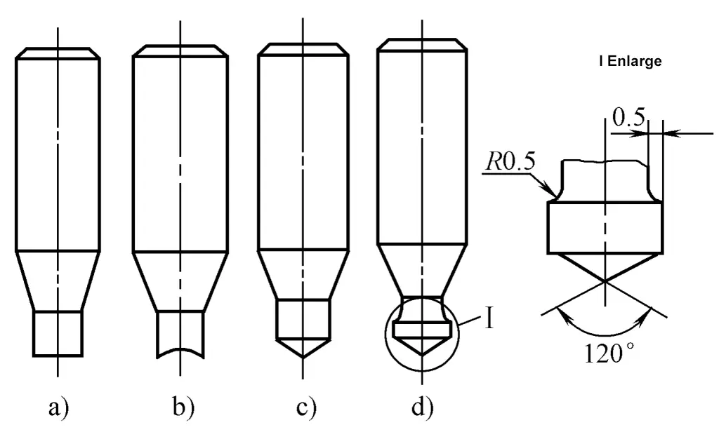
The punch dies shown in Figure 2-2-94a and 2-2-94b are convenient to manufacture and grind, but due to their poor alignment, they have high cutting resistance and are prone to breakage when the material is hard or the tube wall is thick.
Therefore, the punch dies of type 2-2-94a and 2-2-94b are suitable for punching steel tubes with softer materials or wall thickness less than 2mm, while types 2-2-94c and 2-2-94d are suitable for punching steel tubes with harder materials or thicker walls. The punch dies are made of wear-resistant tool steel such as C12, with a required heat treatment hardness of 56~60HRC.
2) Clamping and unloading device.
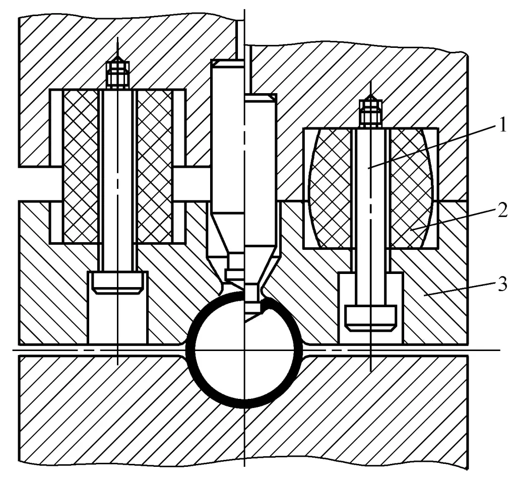
To achieve the requirement of keeping the tube material in a clamped state before and during punching, a clamping device must be set up on the mold. Figure 2-2-95 shows the clamping device for punching on round tubes, which consists of a pressing plate 3, polyurethane rubber 2, and unloading screw 1.
1—Unloading screw
2—Polyurethane rubber
3—Pressing plate
The clamping device has a dual function, not only clamping the tube during punching but also acting as a discharging function when the press slider returns after the stroke. Production practice has proven that using polyurethane rubber instead of general rubber or springs as the elastic element has good effects.
3) Scope of application.
Tube wall without concave die punching, as a “pit” is formed around the punched hole, this process is only suitable for tubes where a “pit” around the punched area is permissible. For most tubes, the “pit” formed during punching provides better results and a smoother and more aesthetically pleasing surface compared to holes made by drilling, boring, or milling.
As shown in Figure 2-2-96, the tube uses the “pit” formed during punching to meet the assembly requirements of the tube well. It is evident that whether to use the concave die-free punching process must first understand if the tube allows for a “pit.”
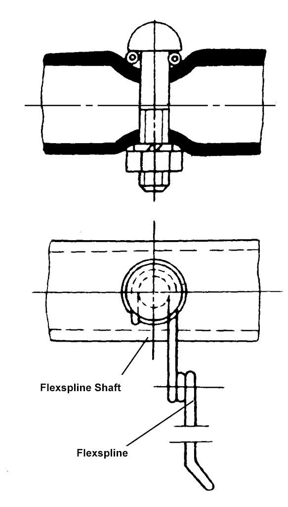
Tube wall without concave die punching, besides being used for punching round holes, oval holes, or special-shaped holes, it can also be used for punching notches (see Figure 2-2-97). Compared to machining holes, this process has lower manufacturing costs, higher production efficiency, and better usage effects, especially suitable for punching tubes in agricultural machinery, electrical appliances, light industry products, with significant economic benefits.

Rubber punching die
Utilizing the deformability and non-flowing polymerization of rubber, placing it inside the tube blank as an elastic convex die, thereby implementing the punching process for any shape of hole on the tube wall, is called rubber die punching.
Rubbers used for punching include natural rubber (black rubber) and polyurethane rubber (synthetic rubber). Since the former can withstand lower unit pressure (generally less than 40MPa), it is only suitable for small-scale production of soft materials and thin-walled tube punching.
Polyurethane rubber is an elastomer that lies between natural rubber and plastic, possessing a range of unique physical and mechanical properties. It not only has high strength and allows for large unit pressures (generally up to 500MPa, and up to 1000MPa when production volumes are small), but also has a wide range of hardness, and is resistant to wear, oil, aging, and tearing, thus it has a long lifespan and can be used for mass production.
(1) Process characteristics
Using polyurethane rubber as the elastic male die and tool steel as the rigid female die, the following process characteristics are exhibited when perforating the tube wall.
1) Since the rubber punching die is a semi-die structure, where the male die is rubber and only the steel female die needs to be manufactured, this simplifies the die manufacturing and solves the problem of difficult matching due to the small clearance between steel male and female dies.
2) Since polyurethane rubber can generate high unit pressures, the diameter of the holes or the width of the slots punched on the tube wall can reach 1 to 2 times the thickness of the material, or even smaller. Practice has shown that when the unit pressure is 500~700MPa, slots with a width of 0.5~0.7mm can be punched in the wall of an aluminum alloy tube with a thickness of 1mm.
According to data from the former Soviet Union, when using polyurethane rubber for punching, the typical diameter of the tube blank ranges from 20~100mm, and the diameter of the holes punched can be 4~40mm; when the tube wall thickness is 0.6~1.5mm, the diameter of the holes punched can even reach 2~3mm. Materials suitable for punching include ordinary carbon steel, stainless steel, non-ferrous metals and their alloys, etc., except for brittle materials, all can be processed with rubber dies.
3) Similar to using polyurethane rubber dies for punching flat parts, the quality of the punched section of the tube is very good, with no burrs. However, on the inside of the tube, due to the action of the polyurethane rubber, a very small radius is formed, which is a significant advantage compared to the burrs formed by machine drilling or milling, eliminating the difficulty of deburring internally.
4) During the punching process, the polyurethane rubber first corrects the diameter of the tube, and then punches according to the edge of the rigid female die, thus achieving high dimensional accuracy of the punched holes. The dimensional accuracy of the punched holes generally reaches IT9~IT11, and for larger holes with thinner materials, it can reach IT6~IT7.
(2) Key points of mold design
The structure of the rubber punching die is shown in figure 2-2-98, mainly consisting of the integral female die sleeve 1, female die 2, polyurethane rubber rod 4, and press head 5. During operation, the tube blank 3 is first placed in the female die, then the polyurethane rubber rod along with the press head (bonded together using polyurethane adhesive) is inserted into the tube blank.
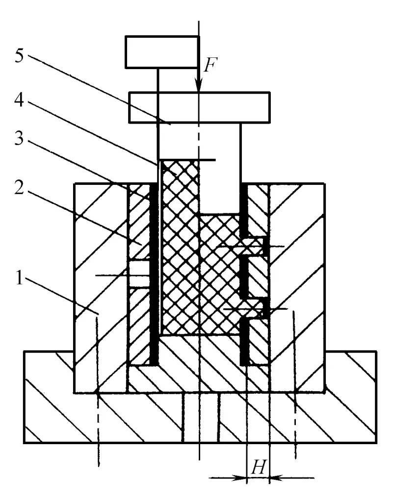
1—Die sleeve
2—Die (segmented structure)
3—Tube blank
4—Polyurethane rubber rod
5—Press head
As the press slide moves downward, the press head presses down, causing the rubber rod to undergo axial compressive deformation and fill the inner cavity of the tube blank, initially correcting the tube diameter. As the press head continues to press down, the pressure inside the sealed rubber unit in the tube blank rises sharply until the material near the edge of the die produces micro-cracks and finally separates, completing the entire punching process.
The wall thickness H value of the punching die (see Figure 2-2-98) must be reasonably determined, as it not only affects whether the punching process can be completed smoothly but also affects the quality of the punched section, the size of the punching force, and the service life of the rubber rod. Based on production experience, the wall thickness H value can be determined by the following formula
H = 2.5(1 + A 10 )√t
Where
- A 10 – Relative elongation rate of the tube blank material (%);
- Wall thickness of the wall blank (mm).
The die is generally made of ordinary tool steel such as T8A, T10A, and after quenching and tempering, the hardness is 56~60HRC. If the die wall is thin or the punching shape is complex, it is better to use alloy tool steel with small deformation after quenching, such as Cr12, Cr12MoV, etc.
The hardness selection of polyurethane rubber should be reasonable. To achieve punching work, it is required that the polyurethane rubber can easily produce lateral deformation after axial compression, to achieve the unit pressure required for punching. According to production experience, it is generally appropriate to select a Shore hardness of 70~80A.
The diameter of the polyurethane rubber rod should be as large as possible to facilitate its removal from the tube blank after completing the punching work, which can reduce the deformation of the polyurethane rubber, help improve its service life, and reduce the tonnage of the press, generally 4%~6% smaller than the inner diameter of the tube blank.
II. Punching of the tube end
After being cut, the tube material becomes the tube blank needed for manufacturing tube fittings. Depending on the requirements of the tube fittings, sometimes various shapes need to be processed at its end. In the past, milling was mostly used to process these types of end shapes, which easily damaged the tools, was inefficient, and not very safe. Currently, punching processing is widely used, which not only improves production efficiency but also ensures stable quality and safety.
Common tube end shapes are shown in Figure 2-2-99, with tube diameters generally ranging from ϕ10 to ϕ70mm and wall thicknesses from 0.5 to 5mm. Due to different end shapes, the mold structure should be flexibly designed after specific analysis. Below are several typical mold structures that have been adopted in production, which can be referred to during design.
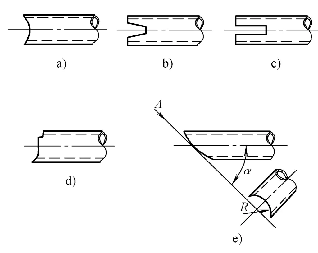
a) End arc
b), c) End slotting
d) Port irregular shape
e) Port inclined arc
1. Port arc punching
The mold structure for punching the arc at the end of the pipe is shown in Figure 2-2-100. The punch 3 is mounted in the fixed plate 2, which is guided by the support plate 1 and one end face of the die 5, to ensure the single-sided punching gap between the punch and the die. The support plate and the die are mounted together on the lower die base 7. Before starting punching, the punch should be adjusted to a position slightly more than one pipe wall thickness away from the arc surface of the die, to facilitate the feeding of the pipe material.
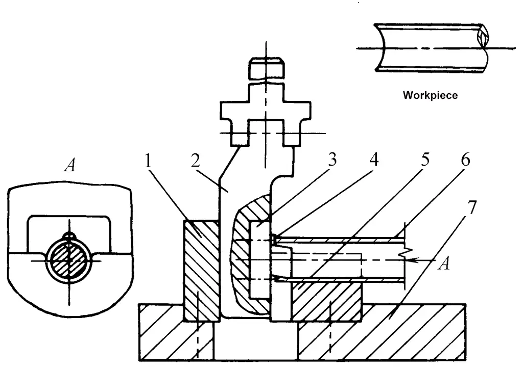
1—Support plate
2—Fixed plate
3—Punch
4—Positioning screw
5—Die
6—Billet
7—Lower die holder
During the operation of the mold, the port is punched twice. During the first punch, the billet 6 is placed on the punch to position it with the positioning screw 4, cutting the lower half of the arc. During the second punch, the billet is flipped 180°, positioned by the arc surface of the punched pipe end, thus completing the entire punching process.
It should be noted that the two-time punching of the pipe end arc is carried out in two separate steps, that is, the first punch (first process) cuts off the lower half arc of all billets, then adjusts the positioning screw to accommodate the positioning for the second punch (second process), and it is not just two consecutive punches on a single billet. Using this mold structure for punching, the stroke of the press should be small and not too large.
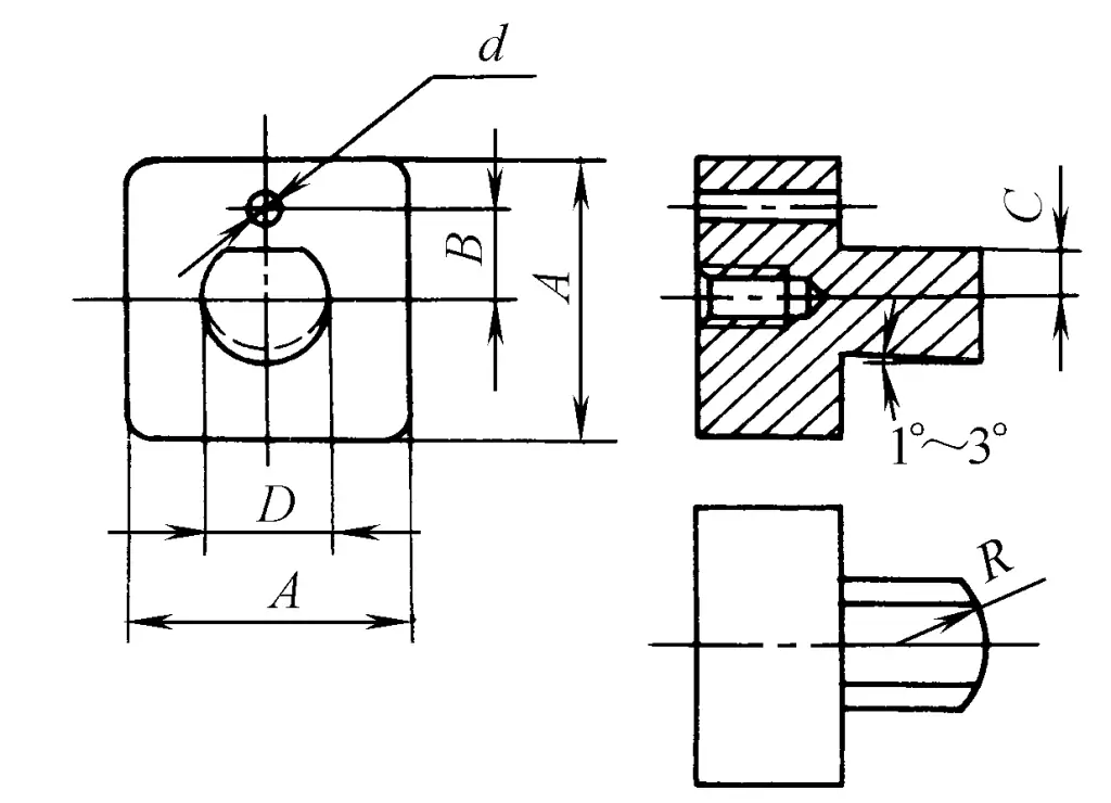
The shape of the punch is shown in Figure 2-2-101, and its dimensional relationship is as follows
- A = D + (10 ~15)mm
- B = (D + d)/2 + t
- C = D/2 – (2 ~5)mm
Where
- D—Internal diameter of the pipe minus 0.5~1mm;
- d—Diameter (mm);
- t—Pipe wall thickness (mm);
- R—Radius of the pipe end arc (mm) (see Figure 2-2-101).
2. Port Slot Punching
The structure of the die for slot punching at the end of the pipe is shown in Figure 2-2-102. The core die 6 is fastened on the fixed plate 3, which can move up and down relative to the lower die base 1 with the help of spring 2 and guide post 4.
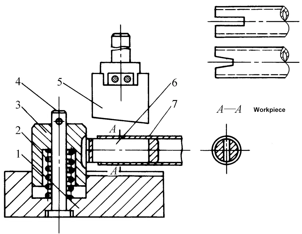
1—Lower die holder
2—Spring
3—Fixed Plate
4—Guide Post
5—Punch Die
6—Core Die
7—Billet
During punching, pressure should be applied on the fixed plate (generally by padding rubber under the press slider). After the core die along with the billet 7 closely adheres to the lower die seat, the punch die 5 starts punching. To improve the edge strength of the core die, the punch die uses a 3°~5° beveled edge. When punching the other side, turn the billet 180°, rely on the already punched notch for positioning, and then perform punching again, thus completing the entire punching process in two stages.
3. Special-shaped punching at the end
The die structure for special-shaped punching at the end of the pipe is shown in Figure 2-2-103. The punch die 2 is guided by the support plate 1, the head shape of the core die 4 matches the concave die 3, and the billet 5 fitted on the core die can be punched. The core die can be lifted and rotated by the pin 6 for easy loading and unloading of the billet.
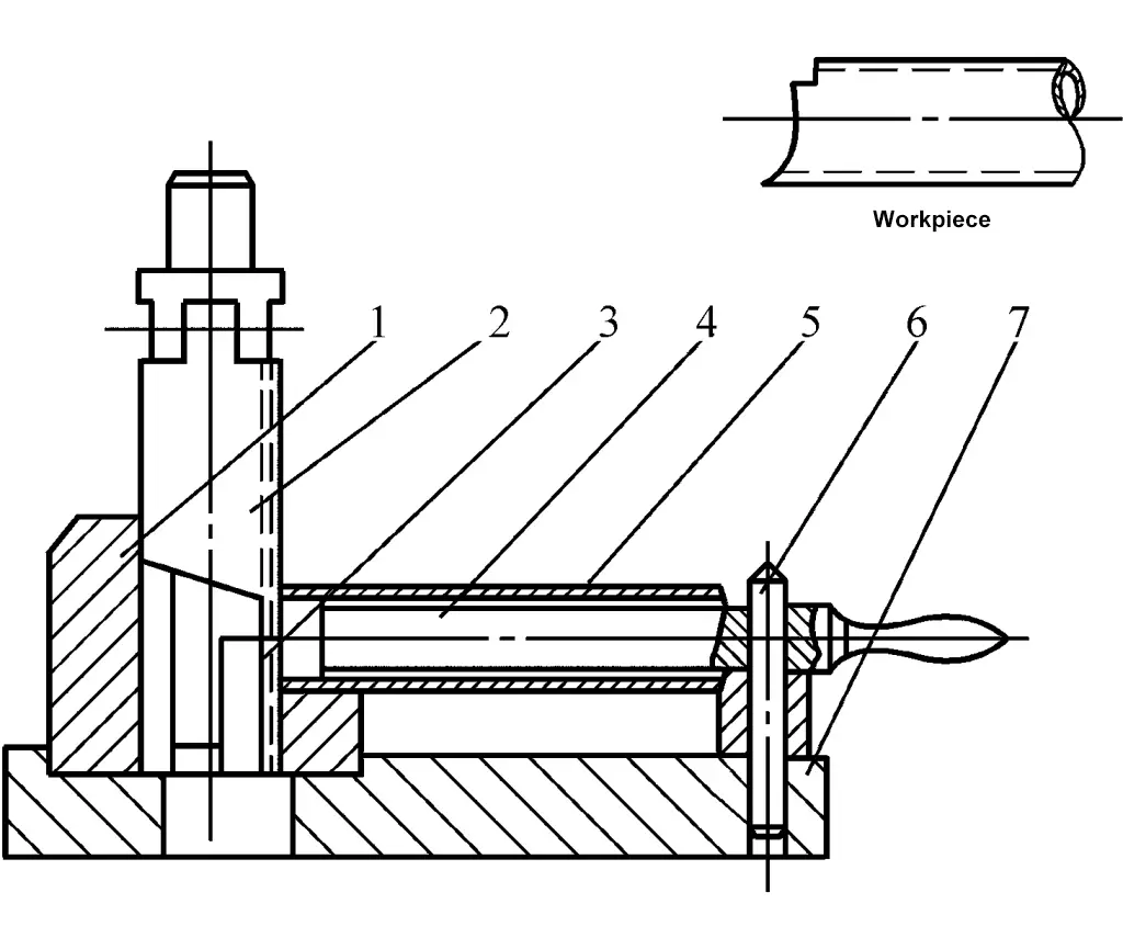
1—Support plate
2—Punch die
3—Die
4—Core die
5—Billet
6—Pin
7—Lower die holder
4. Port inclined arc punching
The mold structure for punching inclined arcs at the tube end is shown in Figure 2-2-104. The arc R of the tube end forms an α angle with the axis of the tube blank and is generally punched on a horizontal press. The convex die 1 with a special-shaped blade and edge is mounted in the press slider, and the concave die 2 is a split type, fixed on the rotatable concave die base around point O by the support plate 4 (not shown in the figure).
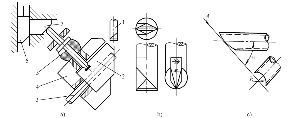
a) Mold structure
b) Convex die structure
c) Workpiece
1—Punch
2—Concave die
3—Tube blank
4—Support plate
5—Press rod
6—Longitudinal wedge
7—Transverse wedge
After the tube blank 3 is inserted into the die, it is clamped with the press rod 5, and punching can be performed by pressing down with the punch. The press rod is pressed by the transverse wedge 7 and the longitudinal wedge 6, which is connected to the press slider. Both wedges are fastened on another base with a slot, and the base can also rotate on the press table centered on point O, and can swing around the arc tangent of the press rod head, this rotation and swing, like the rotatable die base, are to accommodate various different tube end bevel angles α.
Of course, when the angle α changes, just like when the tube diameter size changes, a corresponding die must be designed separately: when the punching arc R changes, a corresponding punch must also be designed separately. The bevel angle α can be punched within the range of 30°~75°, and if the tube end requires punching multiple Rs at angles to each other, it can be completed in several punches.
From the mold structure given above, it can be seen that different mold structures are used because the shapes required for punching at the tube ends are different. This requires mold designers to specifically analyze and study the geometric characteristics of the end shapes of the tube ends according to their different forms, and then cleverly conceive the corresponding mold structures. The mold structure should not only meet the functional requirements of the shape of the punched tube end but should also be easy to operate, safe, and reliable.
III. Punching of Profile Ends
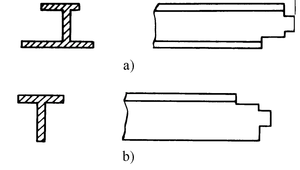
The application of profiles is becoming more widespread, and no matter what kind of profile parts, the first problem to be solved in manufacturing is the cutting process. Profile parts can be divided into three major types according to the cross-sectional shape after cutting: right-angle cutting, 45° cutting, and tenon punching. The cutting of profiles has been introduced in the second part, chapter one, and here only the tenon punching of profiles is discussed.
The common tenon cross-sectional shape is shown in Figure 2-2-105. The profile tenon punching die is shown in Figure 2-2-106, its main feature is that the punch edge is made into a double bevel style, maintaining horizontal and vertical cutting actions when the punch moves downward, separating the web and side in one go, punching out the workpiece.
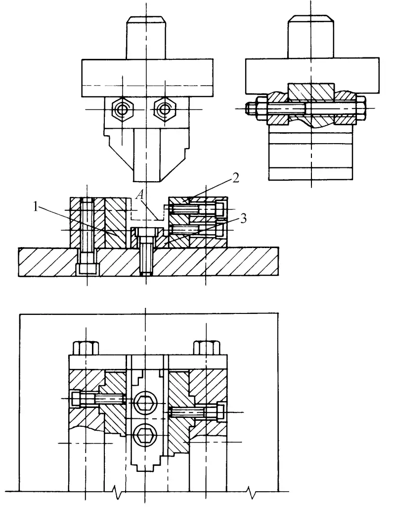
It is generally good to choose a 35°~40° slope for the punch edge. The die uses an insert structure, consisting of six blocks made up of parts 1, 2, and 3, arranged symmetrically on the left and right. The inserts themselves are designed symmetrically, so if one side of the edge is damaged, it can be flipped and continue to be used.
During punching, place the material at the position shown as A in the figure. Because the design raises the height of the inclined blade on one side of the punch equal to the difference in height of the two wings of the profile, this ensures that as the punch moves downward, the double inclined blades simultaneously contact both sides of the profile. Since the horizontal component forces at the contact points on both sides are equal, the stability of the die operation is accordingly improved.
As the punch continues to move downward, while the flat bottom of the punch cuts off the material’s web, the double inclined blades of the punch slice along the two wings of the profile until completely cut through.

