I. Overview
Roll forming of sheet metal (simply called roll forming) is a processing method that involves passing a long strip of metal through a series of forming rolls arranged in a straight line. As the rolls rotate, the strip is advanced forward and sequentially bent to form.
The windscreen frame on the car, the bottom and side plates of the iron carriage, the rims and mudguards of the bicycle, and components such as skylight, showcase, and window sash in the construction industry, are all processed using this method.
The main features of roll forming include:
(1) High production efficiency with a minimal requirement for equipment and workers.
(2) Capable of manufacturing components with very complex cross-sectional shapes, meeting the requirements of structural design to the greatest extent.
(3) Able to achieve high surface finish quality for various shaped parts (maintaining the surface quality of the material).
(4) Can be continuously combined with other process operations: welding (production of welded tubes and bicycle rims), low-temperature welding (production of heat dissipation tubes), bending, perforating, printing, fixed-length shearing, rolling in wire and cardboard, etc.
(5) The main deformation tool of roll forming, the type roller, has a long service life, and its manufacturing is relatively simple and low-cost.
(6) Roll forming can process various materials: soft strip steel, non-ferrous metals and their alloys, stainless steel, and many other materials. The thickness of the material can range from 0.1mm to 20mm, and the width can reach up to 2000mm. Theoretically, the length of the parts can be arbitrary, not limited by equipment conditions.
(7) High material utilization rate.
(8) Due to the uniform work hardening, the stiffness and strength of the parts are significantly improved.
II. Forming Principle
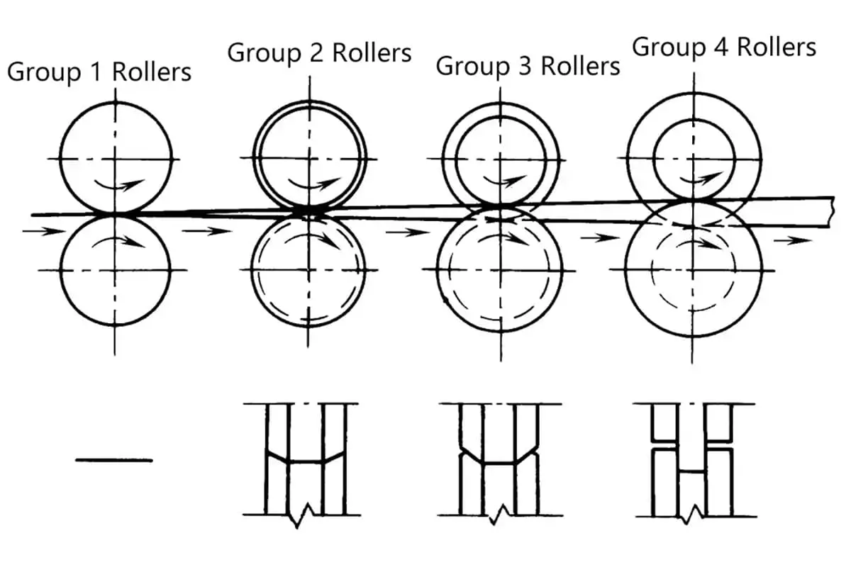
The working principle of roll forming, as shown in Figure 1, is accomplished by sequentially bending and advancing the material through various sets of forming rolls. If we look at the first set of rolls, the forming process, as shown in Figure 2, involves the sheet metal entering the rolls, being bent while moving forward, and being fully formed at the center of the rolls (section 4) before exiting.
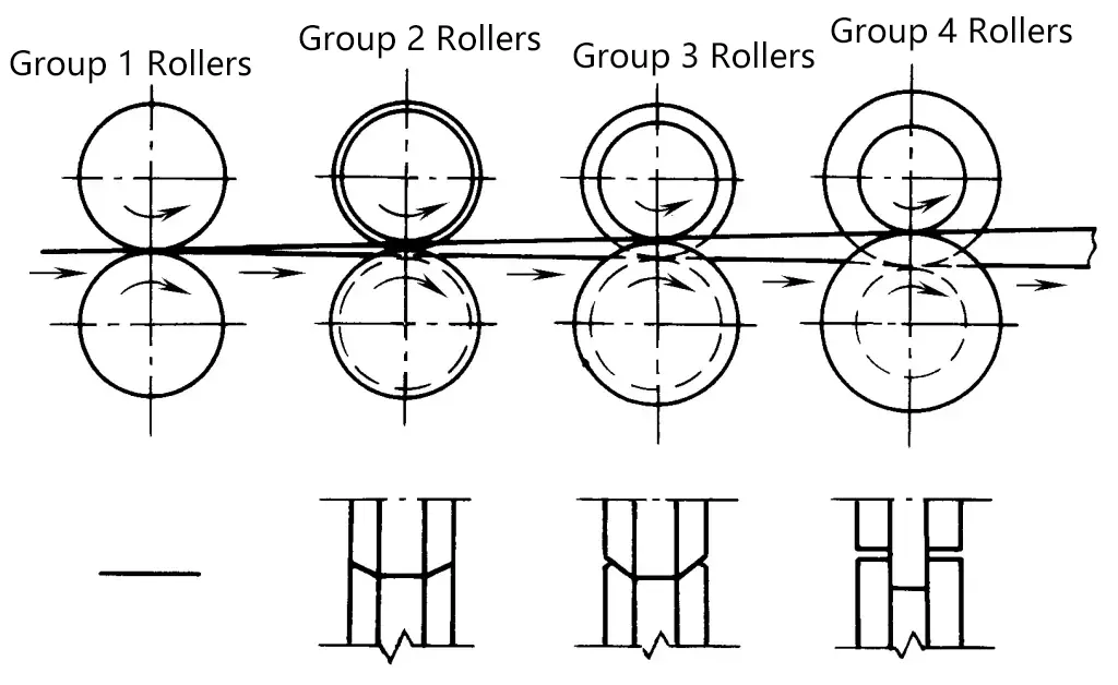
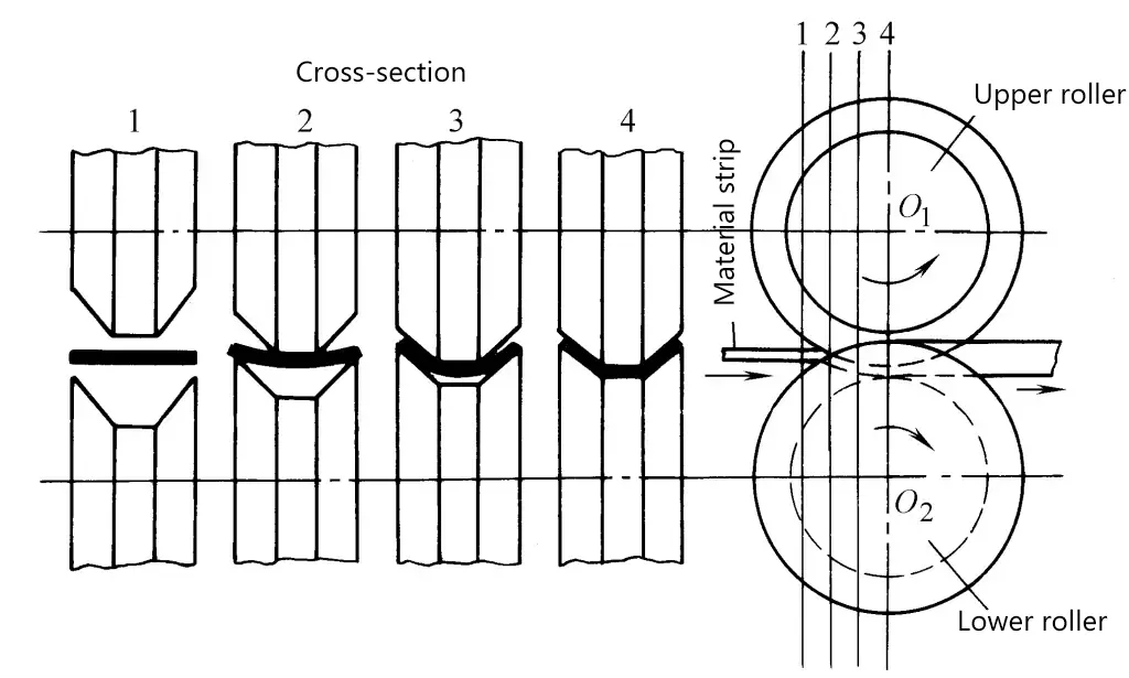
Figure 3 shows the analysis of the rolling pressure on the vertical cross-section during the forming process. Over a small length dx, the vertical components of the central forces pdx/cosθ 1 , pdx/cosθ 2 exerted by the upper and lower rolls correct the bending. Meanwhile, the horizontal components of the central forces pdx·tanθ 1 , pdx·tanθ 2 act in the direction of the material entering and exiting.
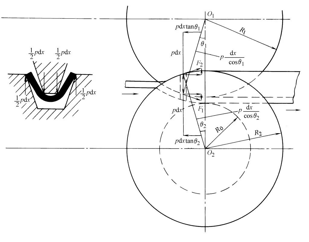
If the friction forces F 1 =μ·pdx/cosθ 1 , F 2 =μ·pdx/cosθ 1 generated by the center cannot overcome the horizontal components of the central forces pdx·tanθ 1 , pdx·tanθ 2 , then the sheet will slip and not advance forward.
According to the actual measurement results of the pressure distribution on the forming rolls, the pressure on the rolls increases from the entrance side and reaches its maximum at the center of the rolls, thereby also maximizing the friction force that advances the material forward. To facilitate the entry of the material ends, an effective method is to shape the ends into triangular strips as much as possible and quickly feed them to the center of the rolls.
III. Process Design
1. Determination of Blank Width
The width of the rolled blank, like the case of mold bending, is calculated based on the unfolded length of the neutral layer.
The curvature radius of the neutral layer in the arc part is
ρ=r+xt
Where in the formula
- r-inner bending radius;
- t-plate thickness;
- x-neutral layer displacement coefficient.
For complex-shaped roll-formed parts, there is an inevitable corner thinning, and the width expansion after roll forming can reach 2% to 5%.
2. The position of the roll-formed blank cross-section in the rolls
When planning the process, it is necessary to select the correct position of the part cross-section relative to the centerline of the rolls.
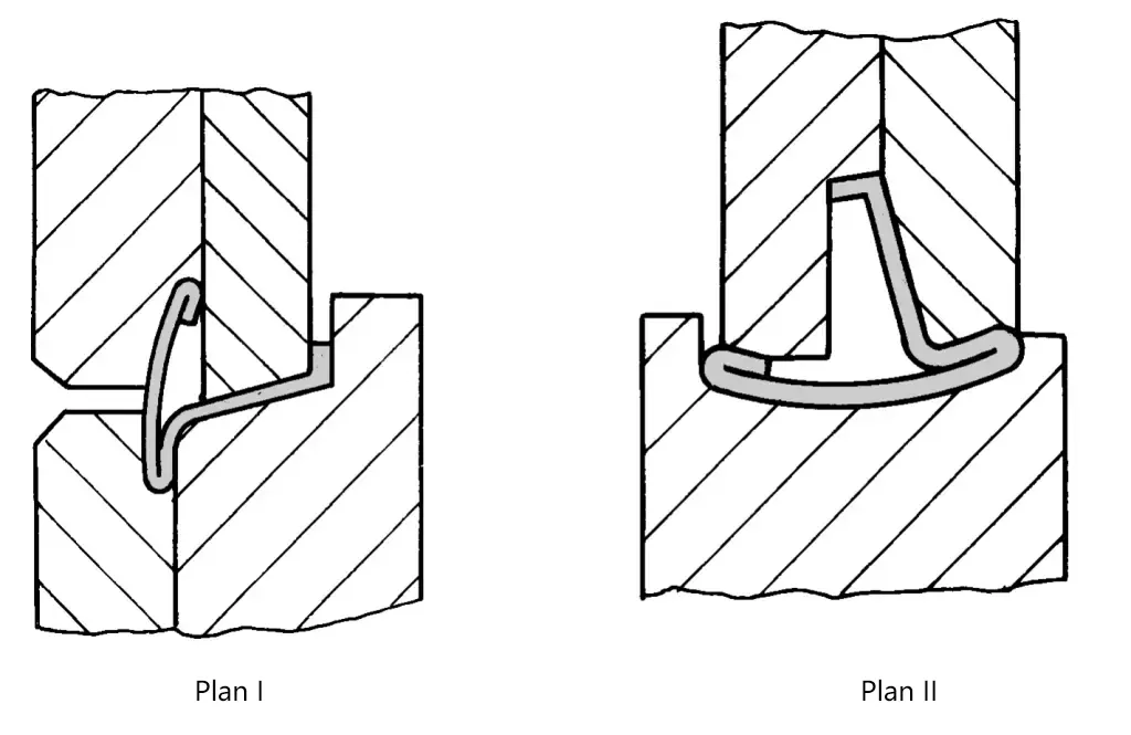
Figure 4 shows the cross-sectional shape of a car windscreen trim, which is also longitudinally bent after roll forming, requiring the assembly dimension a to be ensured, and avoiding scratches on the chrome-plated surface b.

From the perspective of ensuring assembly dimension a, the option I in Figure 5 is better, but to avoid scratching the chrome surface b and to facilitate observation and adjustment, choosing option II is more reasonable.
3. Determination of the Guide Line
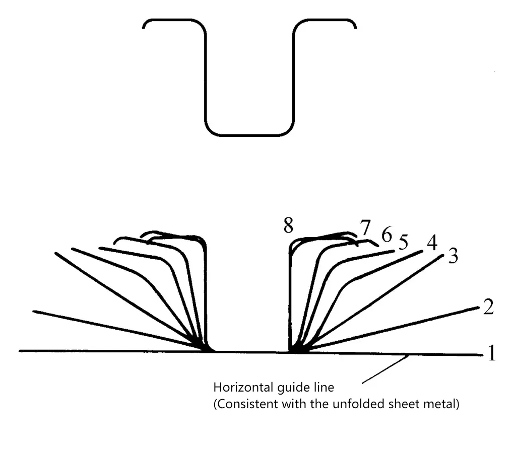
To move the sheet metal from a flat state forward until the required sectional shape is formed, horizontal and vertical guide lines are needed. The horizontal guide line should always be on the same horizontal plane from the first set of rollers to the last set (see Figure 6), which is the basis for determining the diameter of the forming roller circle.
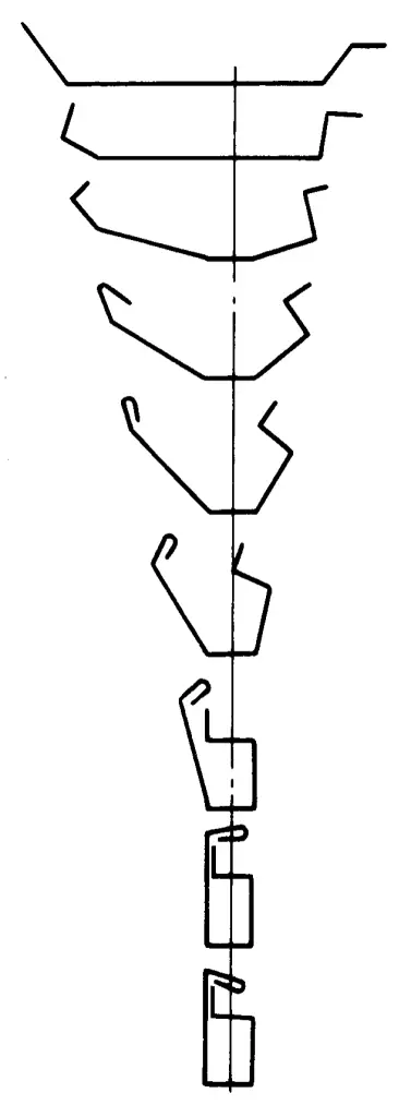
The vertical guide line is perpendicular to the axis of the roller, from the first set of rollers to the last set, making the amount of deformation on both sides of the vertical guide line equal, which is a baseline (see Figure 7). In a symmetrical section, this guide line coincides with the center line of the section.
4. Determination of Roll Pressing Sequence and Bending Angle
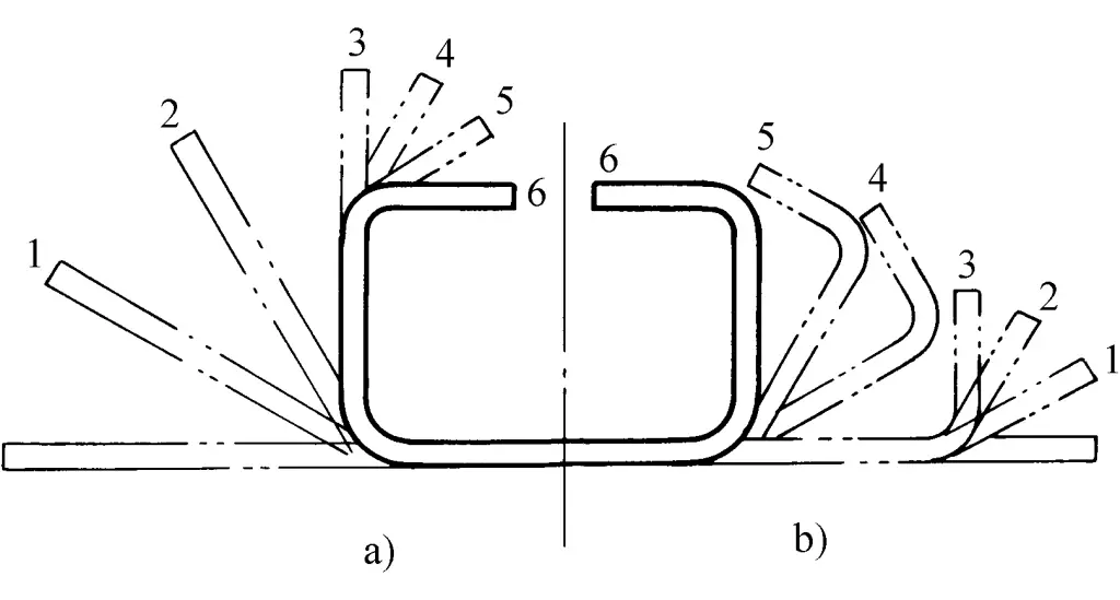
Depending on the different shapes of the roll-pressed section, different roll pressing sequences can be adopted. Usually, adopting the sequence of inside first then outside (see Figure 8a) can make the blank edge straight, reduce lateral flow resistance, and facilitate bending deformation, thus playing a good positioning role. Adopting the bending sequence of outside first then inside (see Figure 8b), can fully utilize the deformation effect of the working roll, improving the tendency of the blank to widen.
The selection of bending angle, with the principle that the angle of a single bend does not exceed the values listed in Table 1.
Table 1 Recommended Maximum Angle for a Single Bend
| Tool Type | Blank Thickness / mm | ||
| 0.5 – 0.8 | 0.8 – 1.2 | 1.2 – 1.5 | |
| Main Roll | 45° | 30° | 22° |
| Auxiliary (Side) Roll | 30° | 20° | 15° |
| Guide Plate | 20° | 15° | 12° |
In a set of rolls, the angle bent at the same time should not exceed two. To compensate for springback, corrections to the bending angle should be made in the later sets of shaping rolls.
When forming the angle of a straight edge, the maximum height of the forming should conform to a linear upward relationship (see Figure 9), and its design method is to control the angle of the forming straight edge (see Table 2).

Table 2 Rising angle of the roll-formed straight edge (recommended value)
| Material of roll forming | Rising angle of the forming straight edge |
| Soft materials | 3° |
| Stainless steel | 1°35′ |
| General metal materials | 1°25′ |
5. Determination of the number of roller groups
For the forming of simple sections, as shown in Figure 9, the rising angle of the forming straight edge is 1°25’, the distance between roller stations is d, and the total length of the forming equipment is L, then the number of roller groups n can be calculated using the following formula
n = L / d = hcot1°25′ / d
For the forming of complex sections, the number of roller groups should be determined based on the specific situation. If support rollers or side rollers are used for lateral processing, the number of vertical forming rollers can be reduced.
6. Determination of the pitch circle diameter of the roller
The diameter of the upper and lower rollers, which is consistent, is the pitch circle diameter of the roller. The forming material can be fed in without slippage on the pitch circle. Outside this point, on the roller diameter, slippage will occur between the roller and the material. From an ideal perspective, it is best to choose the pitch circle at the point where the roller is under the greatest force, but these points are different on each set of forming rollers. Figure 10 is an example of the position of the pitch circle for reference.
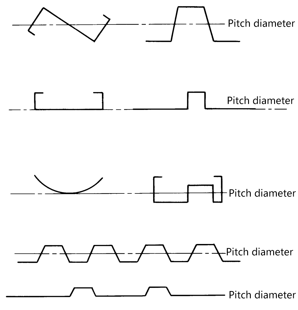
The size of the pitch circle diameter should increase by about 0.4% on each pair of rollers (0.25% when the plate thickness is less than 0.3mm), so as to always stretch the material in the feeding direction, ensuring that there is no “accumulation” phenomenon between each pair of rollers that would disrupt the rolling process.
IV. Roller shape for variable cross-section parts
The roller shapes described above are used for parts with equal cross-sections; for roller shapes for variable cross-section parts, the following takes the automobile beam as an example for illustration.
Figure 11 shows the structural shape of a type of automobile beam. To manufacture such variable cross-section channel-shaped parts, in mass production, they are usually bent and formed with molds on a press: but in medium and small batch production, to reduce equipment investment, roller forming process can also be adopted.

Roller pressing of automobile beams is carried out on a special roller press. This type of roller press uses multiple forming rollers, and the forming rollers must have the following relative movements:
(1) The forming rollers should have longitudinal relative movement to the blank.
(2) According to the shape of the side wall of the car beam, the forming roller needs to make a transverse profiling movement.
Figure 12 shows a schematic diagram of the roller press at work. The mandrel 1 is fixed on the bed, and its shape is consistent with the inner surface of the beam. The slab 2 is fixed on the mandrel 1. Forming rollers 3, 5, 6, and the profiling guide roller 4 are all mounted on the trolley and can move transversely in the groove on the trolley. The trolley can make longitudinal (direction shown by the arrow) reciprocating movement by means of an electric motor through steel wire ropes or chains.
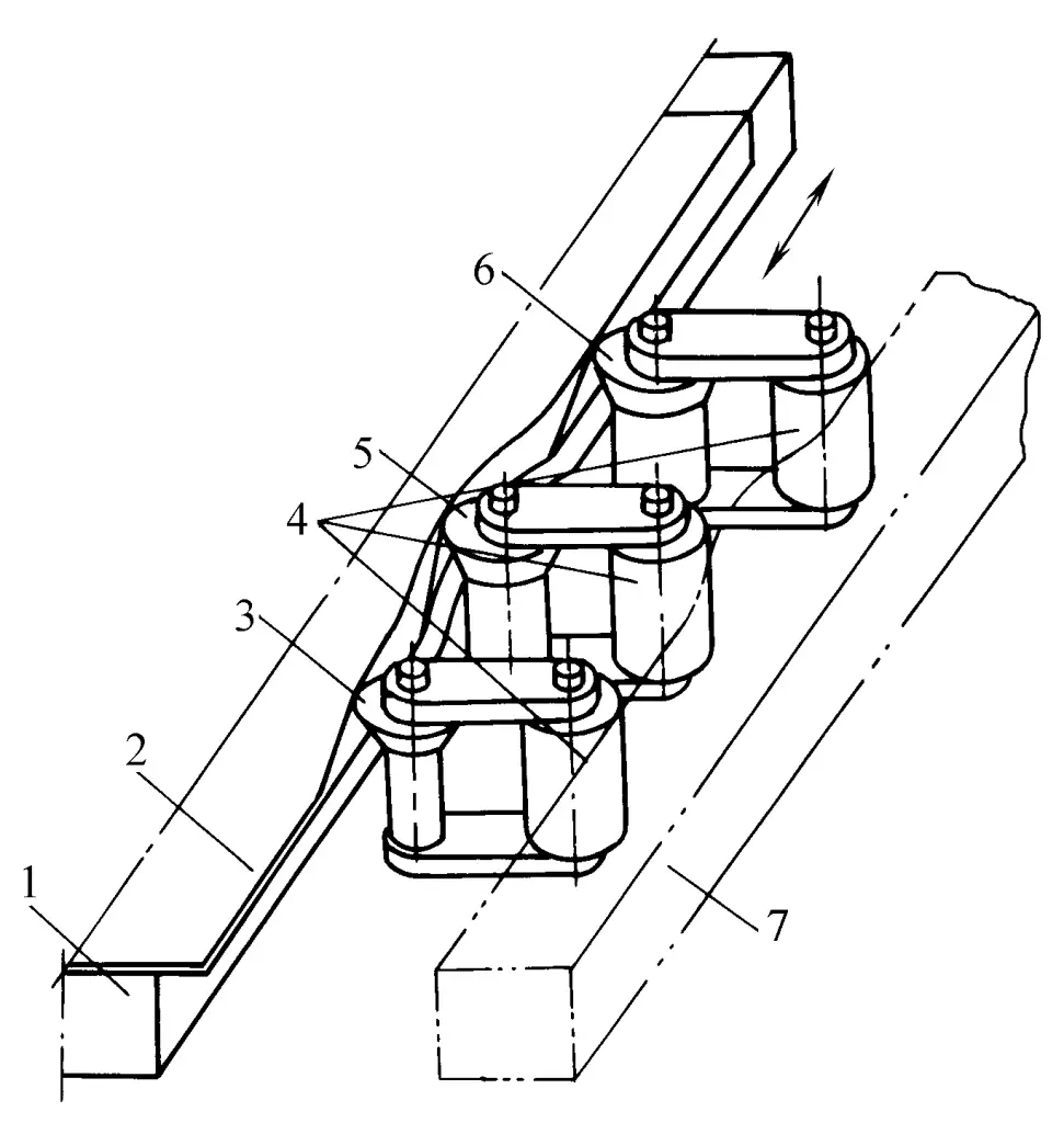
1—Mandrel
2—Slab
3, 5, 6—Forming rollers
4—Guide roller
7—Template
When the trolley moves forward, the forming rollers move with it, and by relying on the profiling guide roller to roll along the template 7. The shape of the template 7 is consistent with the outer side wall shape of the beam, and it is fixed on the side plate of the machine body. The guide roller rolls along the template 7, causing each forming roller to make a transverse profiling movement.
Due to the working conical surface of the forming roller pressing the edge of the plate, the edge of the plate bends, and as the working conical surface angle of each forming roller passing through the edge of the plate increases successively, the bending angle of the edge of the plate also gradually increases, resulting in the final shape. Figure 13 shows a schematic cross-sectional view of the roller press.
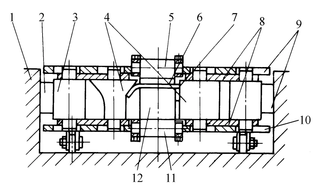
1 – Bed wall plate
2 – Template holder
3 – Template roller
4 – Forming roller
5 – Upper pressing roller
6 – Press plate
7 – Workpiece
8 – Roller connecting plate
9 – Upper and lower cover plates
10 – Forming trolley support wheel
11 – Press down roller
12 – Core mold
During the roll forming of the beam, the deformation process of the plate edge is shown in Figure 14. At a certain instant during the rolling process, the bending angles of the plate edges at each section within the deformation zone L are unequal, with the bending angle under the first roller being α 1 , and under the nth roller, the plate edge is bent to the required angle α n .
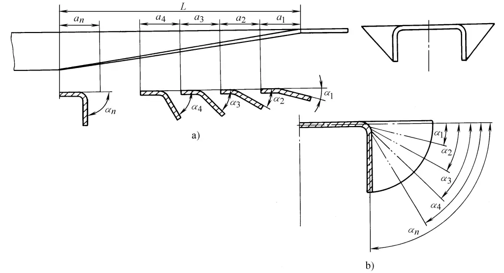
a) Bending angles after rolling by each roller at the same instant
b) Bending angles at the same section after rolling by each roller
For a certain section being rolled, its plate edge is gradually bent. After the first roller passes through this section, its plate edge is bent to α 1 , and with each subsequent roller, the bending angle of the plate edge progressively increases until the nth roller passes, at which point the plate edge is bent to the required angle α n .
The main quality issues currently existing in the roll pressing of beams are longitudinal bending and edge wrinkling. Although these can be somewhat reduced by increasing the diameter of the forming rollers and the number of forming roller passes, a correction process is usually still required after roll pressing before the beams can be used for assembly.

