I. Safety Valve
A safety valve is a valve that acts to prevent the medium pressure from exceeding a specified value. In the pipeline, when the medium working pressure exceeds the specified value, the valve automatically opens to discharge the excess medium; when the working pressure returns to the specified value, it automatically closes.
A safety valve is an automatic pressure relief protection device that is opened by the static pressure at the inlet. It is one of the most important safety accessories for pressure vessels. Its function is: when the pressure inside the vessel exceeds a certain value, the valve automatically opens by the pressure of the medium itself, quickly discharging a certain amount of medium.
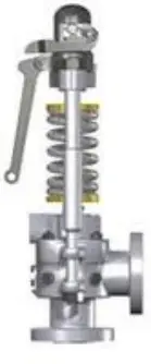
When the pressure inside the vessel drops to an allowable value, the valve automatically closes, ensuring that the internal pressure of the vessel always remains below the upper limit of the allowable pressure, automatically preventing accidents that may occur due to overpressure. Therefore, the safety valve is also known as the ultimate protection device for pressure vessels.
A safety valve is a safety protection valve, whose opening and closing member is normally closed under the action of external force. When the pressure of the medium in the equipment or pipeline rises and exceeds the specified value, it automatically opens, discharging the medium to the system outside to prevent the pressure of the medium inside the pipeline or equipment from exceeding the specified value.
Safety valves belong to the category of automatic valves, mainly used on boilers, pressure vessels, and pipelines to control the pressure not to exceed the specified value, playing an important protective role for personal safety and equipment operation.
1. Common Terminology for Safety Valves
(1) Opening pressure:
When the medium pressure rises to the specified pressure value, the valve disc automatically opens, and the medium is rapidly ejected. At this time, the pressure at the valve inlet is called the opening pressure.
(2) Discharge pressure:
After the valve disc opens, if the medium pressure in the equipment pipeline continues to rise, the valve disc should fully open to discharge the rated amount of medium. At this time, the pressure at the valve inlet is called the discharge pressure.
(3) Closing pressure:
After the safety valve opens and discharges some of the medium, the pressure in the equipment pipeline gradually decreases. When it decreases to a predetermined value less than the working pressure, the valve disc closes, the opening height is zero, and the medium stops flowing out. At this time, the pressure at the valve inlet is called the closing pressure, also known as the reseating pressure.
(4) Working pressure:
The medium pressure during normal operation of the equipment is called the working pressure. At this time, the safety valve is in a sealed state.
(5) Discharge capacity:
When the discharge medium valve disc is fully open, the amount of medium discharged from the valve outlet per unit of time is called the valve’s discharge capacity.
2. Types of safety valves
Safety valves vary in structure due to different uses, but they are generally classified by the following methods
(1) According to the structure of the safety valve, it can be divided
1) Dead weight (lever) type safety valve:
Uses a lever and dead weight to balance the pressure of the valve disc. The dead weight safety valve adjusts the pressure by moving the position of the dead weight or changing the weight of the dead weight. Its advantage is that it has a simple structure; the disadvantage is that it is relatively bulky and has low reseating force. This type of safety valve can only be used on fixed equipment. As shown in the far left image in Figure 1.
2) Spring type safety valve:
Uses the force of a compressed spring to balance the pressure of the valve disc and keep it sealed. The spring type safety valve adjusts the pressure by adjusting the compression amount of the spring. Its advantage is that it is smaller in volume, lighter, and more sensitive than the dead weight type safety valve, and its installation position is not strictly limited; the disadvantage is that the force acting on the valve stem changes with the deformation of the spring.
At the same time, attention must be paid to the insulation and heat dissipation of the spring. The spring force of the spring type safety valve generally should not exceed 2000 kilograms. This is because springs that are too large and too stiff are not suitable for precise work. As shown in the middle image in Figure 1.
3) Pilot-operated safety valve:
Pilot-operated safety valves are usually used on large-diameter pipelines. This is because large-diameter safety valves are not suitable when using dead weight or spring types. The pilot-operated safety valve consists of a main valve and an auxiliary valve. The main valve and auxiliary valve are connected together, and the main valve is actuated by the pulse action of the auxiliary valve. As shown in the far right image in Figure 1.
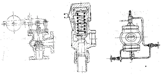
When the medium in the pipeline exceeds the rated value, the auxiliary valve acts first to drive the main valve, discharging the excess medium.
4) Micro-lift safety valve.
The opening height of the valve disc is 1/40 to 1/20 of the valve seat diameter, such as A27W-10T, A47H-16C safety valves.
5) Full-lift safety valve.
For example, the A47H-16C type safety valve. The opening height of the valve disc is 1/4 of the valve seat diameter.
6) Full-closed safety valve.
Such as the A47H-16C type safety valve.
7) Semi-closed safety valve.
Such as the A48Y-16C safety valve.
8) Open safety valve.
(The A48Y-16C safety valve is also an open type)
9) Pilot-operated safety valve.
Such as the WFXD type safety valve.
(2) According to the ratio of the maximum opening height of the safety valve disc to the valve seat diameter, it can also be divided into:
1) Micro-lift:
The opening height of the valve disc is 1/20 to 1/10 of the valve seat diameter. As shown in the left diagram of Figure 2. Since the opening height is small, the requirements for the structure and geometric shape of this type of valve are not as strict as those of the full-lift type, making design, manufacturing, maintenance, and testing more convenient, but the efficiency is lower.
2) Full-lift:
The opening height of the valve disc is 1/4 to 1/3 of the valve seat diameter. As shown in the right diagram of Figure 2.
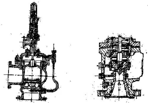
The full-lift safety valve relies on the expansion thrust of the gas medium to raise the valve disc to a sufficient height and displacement. It uses the upper and lower adjusting rings of the valve disc and seat to create a pressure zone between the discharged medium and the upper and lower valve rings, causing the valve disc to rise to the required opening height and specified reseating pressure. This structure is highly sensitive and widely used, but the positions of the upper and lower adjusting rings are difficult to adjust, and careful use is required.
(3) According to the construction of the safety valve body, it can be divided into
1) Fully enclosed:
When discharging the medium, there is no leakage to the outside, and it is all discharged through the discharge pipe.
2) Semi-enclosed:
When discharging the medium, part of it is discharged through the discharge pipe, and another part leaks out from the joint between the valve cover and the valve stem.
3) Open type:
When discharging the medium, it is not led outside, and it is directly discharged from the valve disc.
(4) According to the connection method:
1) Flange-connected safety valve.
The safety valve inlet and the pipeline are connected by a flange, and the outlet form is flexible.
2) Threaded connection safety valve.
The safety valve inlet and the pipeline are connected by threads, and the outlet form is flexible.
3) Welded connection safety valve.
The safety valve inlet and the pipeline are connected by threads, and the outlet form is flexible.
(5) According to the applicable temperature:
1) Ultra-low temperature safety valve:
Safety valve for temperatures ≤ -100℃
2) Low-temperature safety valve:
Safety valve for temperatures -100℃ < -40℃.
3) Normal temperature safety valve:
Safety valve for -40℃≤t≤120℃
4) Medium temperature safety valve:
Safety valve for 120℃<t≤450℃
5) High temperature safety valve:
Safety valve for t>450℃
It should be particularly pointed out that, in view of the actual situation of spring manufacturing in China, when safety valves are used for conditions above 350℃, they mostly use radiators or make the valve cover basket-shaped, so that the spring can dissipate heat better, ensuring that it always works below 350℃, to ensure its stiffness remains unchanged, thereby guaranteeing the correct opening and reseating of the safety valve and other performance requirements.
(7) Classified by nominal pressure:
1) Low pressure safety valve:
Safety valve with nominal pressure PN≤1.6Mpa
2) Medium pressure safety valve:
Safety valve with nominal pressure PN2.5-6.4Mpa
3) High pressure safety valve:
Safety valve with nominal pressure PN10.0-80.0Mpa
4) Ultra-high pressure safety valve:
Safety valve with nominal pressure PN>100Mpa
(8) Classified by the medium used:
1) Safety valve for steam
Usually represented by model A48Y
2) Safety valve for air and other gases
Usually represented by model A42Y
3) Safety valve for liquids
Typically represented by the A41H model
(9) Classification by the presence of a back pressure balancing mechanism
1) Back pressure balanced safety valve.
Utilizes components such as bellows, pistons, or diaphragms to balance the back pressure effect, making the valve’s opening pressure before lift balanced on both sides of the disc.
2) Conventional safety valve.
Safety valve without back pressure balancing components.
(10) Classification by operating characteristics
1) Proportional action safety valve.
Safety valve whose opening pressure gradually changes as the pressure increases.
2) Two-stage safety valve.
Also called pop action safety valve. The opening process is divided into two stages: initially, the disc opens proportionally as the pressure increases, and after a small increase in pressure, the disc rapidly opens to the specified height almost without further increase in pressure.
(10) Classification by sealing pair
1) Hard alloy to hard alloy sealing pair.
Suitable for high temperature and high pressure situations, especially for high temperature and high pressure superheated steam.
2) 2Cr13 to 2Cr13 sealing pair.
Used for saturated steam and superheated steam in general situations, or for containers or pipelines with other media at temperatures below 450°C.
3) Valve seat sealing surface is 2Cr13, valve disc sealing surface is hard alloy.
Used for high-pressure steam and other media with relatively high flow rates that are likely to cause erosion on the sealing surface.
4) Valve seat sealing surface is alloy steel, valve disc sealing surface is polytetrafluoroethylene (PTFE).
Suitable for oil or natural gas media, with strict sealing requirements, but operating temperature below 150°C.
5) The sealing pair is made of austenitic stainless steel.
The valve body and bonnet of this type of safety valve are mostly made of austenitic stainless steel, used in media containing corrosive components such as acids and alkalis.
3. Selection criteria for safety valves:
(1) Full-lift spring safety valves are generally used for steam boiler safety valves;
(2) For liquid media safety valves, micro-lift spring safety valves are generally used;
(3) For air or other gas media safety valves, full-lift spring safety valves are generally used;
(4) For safety valves used in liquefied petroleum gas vehicle tanks or railway tank cars, full-lift internal safety valves are generally used;
(5) For safety valves used at the outlet of oil wells, pilot-operated safety valves are generally used;
(6) For high-pressure bypass safety valves of steam power generation equipment, pilot-operated safety valves with both safety and control functions are generally used;
(7) If regular opening tests are required for the safety valve, safety valves with lifting levers should be used. When the medium pressure reaches more than 75% of the opening pressure, the lifting lever can be used to slightly lift the valve disc from the seat to check the flexibility of the safety valve opening;
(8) If the medium temperature is high, to reduce the temperature of the spring chamber, safety valves with radiators should be used when the temperature of closed safety valves exceeds 300°C and the temperature of open safety valves exceeds 350°C;
(9) If the back pressure at the outlet of the safety valve is variable and the variation exceeds 10% of the opening pressure, bellows safety valves should be used;
(10) If the medium is corrosive, bellows safety valves should be used to prevent important parts from failing due to corrosion by the medium.
4. The following points should be noted for the installation and maintenance of safety valves:
(1) All types of safety valves should be installed vertically.
(2) There should be no obstruction at the outlet of the safety valve to avoid pressurization.
(3) Safety valves should be tested specifically before installation and their sealing performance checked.
(4) Safety valves in use should be inspected regularly.
5. Recommended types of steam traps for various steam heating equipment
Table 1 Recommended types of steam traps for various steam heating equipment
| Steam heating equipment | Recommended types of steam traps | |
| Main steam pipe, tracing pipe, steam jacket | Disc type, float type | |
| Steam-water separator | Float type | |
| Air heater, hot air unit | Float type | |
| Heating radiators | Corrugated tube type, bimetallic strip type, diaphragm type | |
| Heat exchanger | Steam inlet equipped with temperature control valve | Float type |
| Steam inlet not equipped with temperature control valve | Bimetallic strip, float type | |
| Evaporator | Float type, open downward float type | |
| Jacketed kettle | Bimetallic strip | |
| Heating coil immersed in liquid tank | Steam inlet equipped with temperature regulating valve | Float type |
| Steam inlet without temperature regulating valve | Bimetallic strip type, diaphragm type | |
| Drum dryer | Float type (with anti-steam-lock device), bimetallic strip type | |
| Ironing machine | Disc type, bimetallic strip type, diaphragm type | |
| Dry cleaning machine | Float type | |
| Drying room (box) | Float type | |
| Sterilizer | Corrugated tube type, bimetallic strip type | |
| Vulcanizing bed | Float type, open downward float type | |
| Laminating machine | Disc type, bimetallic strip type | |
| Steam heating equipment below atmospheric pressure | Pump type steam trap | |
II. Pressure reducing valve
1. What is a pressure reducing valve
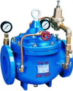
A pressure reducing valve uses the opening of the closure member inside the valve body to regulate the flow of the medium, reduce the pressure of the medium, and at the same time, adjust the opening of the closure member with the effect of the downstream pressure to keep the downstream pressure within a certain range. By injecting cooling water inside the valve body or downstream, the temperature of the medium is reduced. Such a valve is called a pressure reducing and temperature reducing valve.
The characteristic of the pressure reducing valve is that it maintains the outlet pressure and temperature values within a certain range despite the constantly changing inlet pressure.
The pressure reducing valve is an essential accessory for pneumatic control valves, whose main function is to reduce and stabilize the pressure of the air source to a set value so that the control valve can obtain a stable air source power for regulation and control.
According to the structural form, it can be divided into diaphragm type, spring diaphragm type, piston type, lever type, and bellows type; according to the number of valve seats, it can be divided into single-seat and double-seat types; according to the position of the valve disc, it can be divided into direct acting type and reverse acting type.
2. Basic performance of pressure reducing valve
(1) Pressure adjustment range:
It refers to the adjustable range of the output pressure P2 of the pressure reducing valve, within which the specified accuracy is required. The pressure adjustment range is mainly related to the stiffness of the pressure adjustment spring.
(2) Pressure characteristics:
It refers to the characteristics of the output pressure fluctuations caused by fluctuations in the input pressure when the flow rate g is fixed. The smaller the output pressure fluctuation, the better the characteristics of the pressure reducing valve. The output pressure must be below a certain value of the input pressure to remain essentially unchanged with variations in the input pressure.
(3) Flow characteristics:
It refers to the characteristics of the output pressure changing with the output flow rate g when the input pressure is fixed. The smaller the change in output pressure when the flow rate g changes, the better. Generally, the lower the output pressure, the smaller the fluctuation with the change in output flow rate.
3. Selection of pressure reducing valve
Select the type and pressure regulation accuracy of the pressure reducing valve according to the usage requirements, and then choose its diameter based on the required maximum output flow rate. When determining the valve’s air source pressure, it should be more than 0.1MPa higher than the highest output pressure.
The pressure reducing valve is generally installed after the water separator and air filter, and before the oil mist device or set value device, and care should be taken not to reverse the inlet and outlet connections; when the valve is not in use, the knob should be loosened to avoid deformation of the diaphragm due to constant pressure and affecting its performance.
Selection standards:
(1) Within the given range of spring pressure levels, the outlet pressure should be continuously adjustable between the maximum and minimum values without jamming or abnormal vibration;
(2) For soft-sealed pressure reducing valves, there should be no leakage within the specified time; for metal-sealed pressure reducing valves, the leakage should not exceed 0.5% of the maximum flow rate.
(3) When the outlet flow changes, the outlet pressure deviation of the direct-acting type shall not exceed 20%, and that of the pilot-operated type shall not exceed 10%;
(4) When the inlet pressure changes, the outlet pressure deviation of the direct-acting type shall not exceed 10%, and that of the pilot-operated type shall not exceed 5%;
(5) Usually, the pressure after the pressure reducing valve should be less than 0.5 times the pressure before the valve;
(6) Pressure reducing valves have a wide range of applications and can be used on equipment and pipelines with steam, compressed air, industrial gases, water, oil, and many other liquid media. The amount of medium passing through the outlet of the pressure reducing valve is generally expressed in terms of mass flow or volume flow;
(7) Bellows direct-acting pressure reducing valves are suitable for low-pressure, medium and small diameter steam media;
(8) Diaphragm direct-acting pressure reducing valves are suitable for medium and low pressure, medium and small diameter air and water media. If made of stainless acid-resistant steel, they can be used for various corrosive media;
(9) Pilot-operated piston pressure reducing valves are suitable for various pressures, diameters, and temperatures of steam, air, and water media;
(10) Pilot-operated bellows pressure reducing valves are suitable for low-pressure, medium and small diameter steam, air, and other media;
(11) Pilot-operated diaphragm pressure reducing valves are suitable for low and medium pressure, medium and small diameter steam or water and other media;
(12) The fluctuation of the inlet pressure of the pressure reducing valve should be controlled within 80% to 105% of the set value of the inlet pressure. If it exceeds this range, the performance of the pressure reduction at the initial stage will be affected;
(13) Usually, the pressure after the pressure reducing valve should be less than 0.5 times the pressure before the valve;
(14) Each spring of the pressure reducing valve is only applicable within a certain range of outlet pressure. If the range is exceeded, the spring should be replaced;
(15) In situations where the medium working temperature is relatively high, pilot-operated piston pressure reducing valves or pilot-operated bellows pressure reducing valves are generally chosen;
(16) For media such as air or water (liquid), it is generally advisable to choose direct-acting diaphragm pressure reducing valves or pilot-operated diaphragm pressure reducing valves;
(17) For steam media, pilot-operated piston or pilot-operated bellows pressure reducing valves should be chosen;
(18) For convenience of operation, adjustment, and maintenance, the pressure reducing valve should generally be installed on a horizontal pipeline.
4. The following points should be noted for the installation and maintenance of pressure reducing valves:
(1) For ease of operation and maintenance, the valve is generally installed upright on a horizontal pipeline.
(2) During installation, care should be taken to ensure that the direction of the medium flow in the pipeline is consistent with the direction of the arrow indicated on the valve body.
(3) To prevent overpressure after the valve, a pressure reducing valve should be installed at a distance of not less than 4 meters from the valve outlet.
5. Function and application of pressure reducing valve:
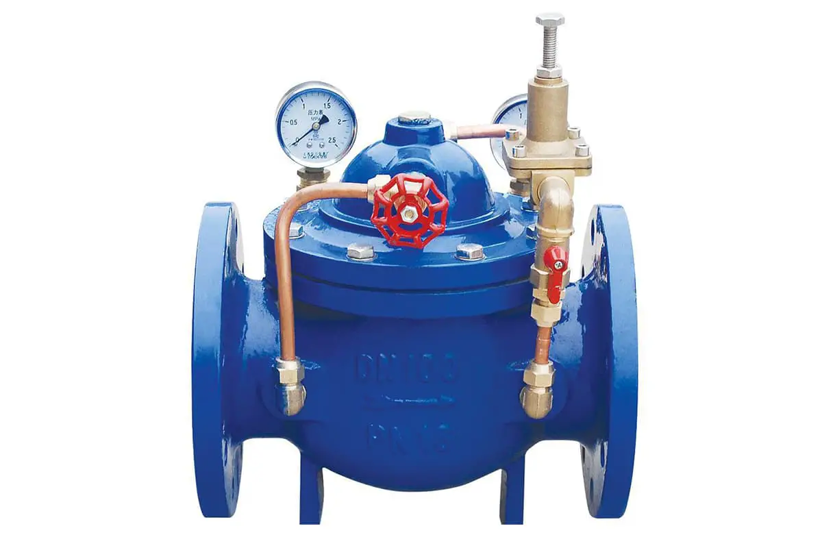
The 200X pressure reducing valve is an intelligent valve that uses the medium’s own energy to regulate and control pipeline pressure. It is used for domestic water supply, fire water supply, and other industrial water supply systems. By adjusting the pilot valve of the pressure reducing valve, the outlet pressure of the main valve can be adjusted.
The outlet pressure remains unchanged despite changes in inlet pressure and flow rate, safely and reliably maintaining the outlet pressure at the set value, and the set value can be adjusted as needed to achieve the purpose of pressure reduction. This valve has precise pressure reduction, stable performance, safety and reliability, easy installation and adjustment, and a long service life.
6. Technical parameters of pressure reducing valve:
The pressure reducing valve mainly controls the fixed outlet pressure of the main valve, the outlet pressure of the main valve does not change with the change of inlet pressure, and does not change its outlet pressure with the change of outlet flow of the main valve. Suitable for industrial water supply, fire water supply, and domestic water supply network systems.
The technical parameters of the pressure reducing valve mainly include the following:
- Nominal pressure: 1.0MPa, 1.6MPa, 2.5MPa
- Shell test pressure: P=1.5PN
- Seal test pressure: P=1.1PN
- Outlet pressure: PN1.0MPa regulating valve 0.09~0.8MPa; PN1.6MPa regulating valve 0.10~1.2MPa; PN2.5MPa regulating valve 0.15~1.6MPa
- Applicable medium: water
- Applicable temperature: 0℃~80℃

