I. Methods of Assembly
According to the specified technical requirements, the process of fitting and connecting parts or components to make them into semi-finished or finished products is called assembly. Assembly processing is essentially a process of positioning, clamping, and connecting. In the assembly of sheet metal parts, support, positioning, and clamping are called the three elements of assembly, which are also the three basic conditions of assembly.
Clamping is the process of fixing parts in a certain position with external force, so that the parts involved in the assembly maintain their position during assembly.
1. Selection of Assembly Reference
Conventionally, support is also called assembly reference, abbreviated as reference. It solves the problem of where to assemble sheet metal components by selecting a reference surface. In the actual assembly of sheet metal components, the best reference surface should be selected based on specific conditions.
When selecting the assembly reference surface as the assembly support, the following points can be considered:
- When a component has both flat and curved surfaces, the flat surface should be used as the assembly reference surface.
- When a component has both large and small flat surfaces, the larger flat surface should be selected as the assembly reference surface.
- When a component has both machined and rough surfaces, the machined surface should be selected as the assembly reference surface.
- The selected assembly reference surface should be most convenient for supporting, positioning, and clamping the parts.
- A surface that is not easily deformed should be selected as the reference surface to avoid positioning errors caused by deformation of the reference surface or line.
2. Methods of Positioning
Determining the position or relative position of a part in space is called positioning. Positioning is one of the first problems to be solved during assembly. The principle of positioning is based on the “six-point positioning principle,” which states that any rigid body in space has 6 degrees of freedom with respect to three mutually perpendicular coordinates, namely axial movement along these three mutually perpendicular axes and rotation around these axes.
To ensure that the workpiece maintains a fixed and unchanged position during assembly and achieve accurate positioning, the 6 degrees of freedom of the workpiece should be restricted. In sheet metal assembly, the assembly position is usually determined by marking assembly position lines or using positioning elements such as stop blocks and positioning pins to fix the assembly position. Table 1 shows common positioning methods for parts.
Table 1 Common Positioning Methods for Parts
Type | Diagram |
Line Positioning | 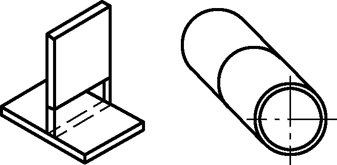 |
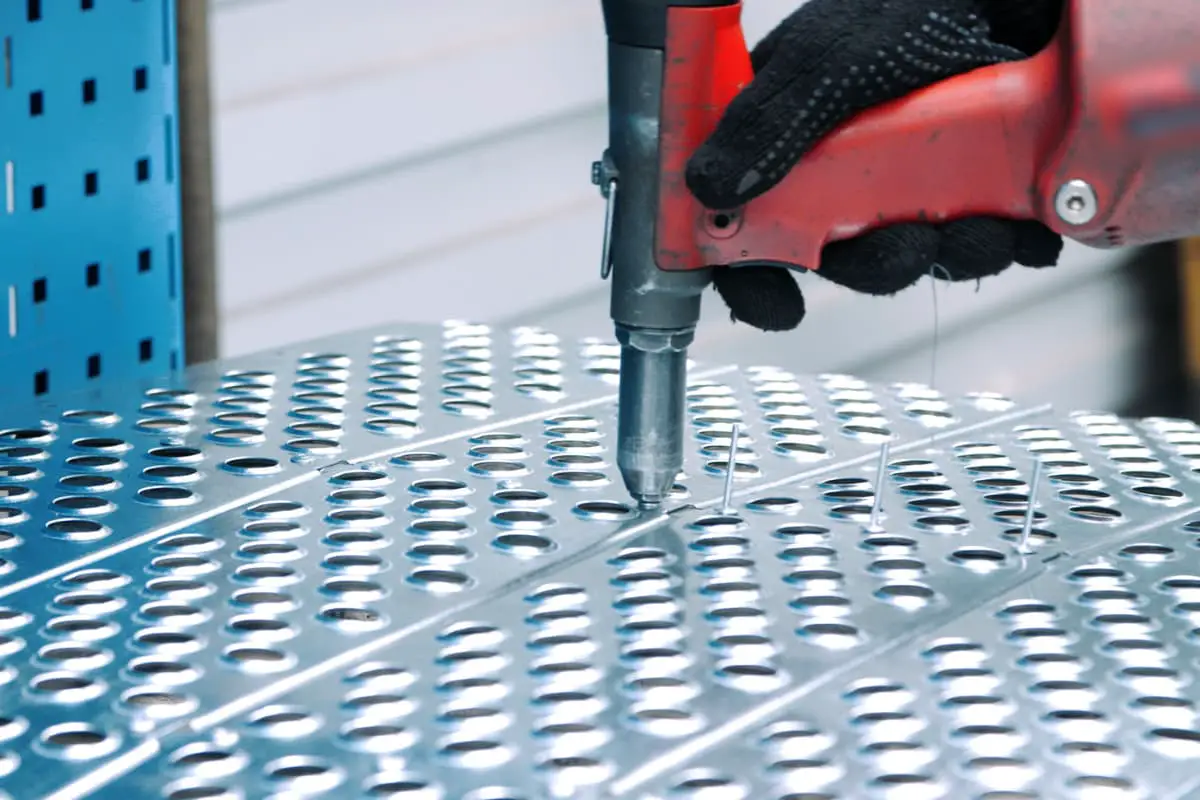
Pin Positioning | 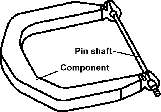 |
Stop Block Positioning | 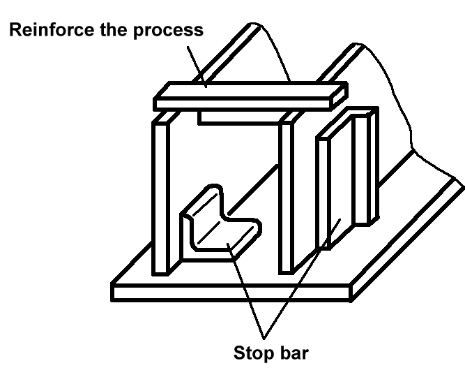 |
Template Positioning | 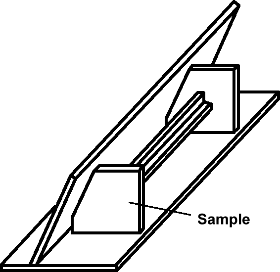 |
In addition, in the actual assembly of sheet metal components, the positioning reference should be determined based on specific conditions. The selection of positioning reference can be based on the following points:
1) For various parts on the same component that have connections or fitting relationships with other components, the same positioning reference should be used as much as possible. This ensures the correct connection or fitting of the component with other components during installation.
2) Select surfaces or edges with high precision and not easily deformed as the positioning reference to avoid positioning deviations caused by deformation of the reference surface or line.
3) The selected positioning reference should facilitate the positioning measurement of each component during the assembly process. Measurements during assembly include measuring the dimensions of the product, as well as measuring and ensuring the accuracy of the product’s shape and position, and measuring and selecting the assembly base surface.
3. Methods of Clamping
The operation of fixing a workpiece after positioning to keep it in a fixed position during the manufacturing process is called clamping. Clamping is also commonly referred to as fixturing.
There are four methods of fastening workpieces using assembly fixtures: clamping, pressing, pulling, and jacking (supporting), as shown in Figure 1. The tools shown in the figure are common spiral tools, characterized by adjustability and ease of use.

a) Clamping (Spiral Clamp, Cam)
b) Pressing (Bolt Pressing)
c) Pulling (Spiral Puller)
d) Jacking (Spiral Pusher)
Common assembly fixtures are classified by the method of applying force, including wedge fixtures, lever fixtures, spiral fixtures, toggle fixtures, and eccentric fixtures. Various lifting tools are also used in sheet metal assembly for bundling and handling.
4. Main Methods of Assembly
Depending on the structure of the assembled components, different methods are often chosen for the assembly of sheet metal components. Based on different positioning methods, the main assembly methods include line assembly, copy assembly, and profiling assembly; based on different assembly orientations, the main assembly methods include horizontal assembly (flat assembly), vertical assembly (upright assembly), and inverted assembly. The main assembly methods and their characteristics are as follows.
(1) Line Assembly
Line assembly, also known as ground template assembly, involves drawing cross lines on a base plate (or ground) as assembly references, then drawing contour position lines and joint lines of the components at a 1:1 actual size, and assembling according to the lines. Line assembly is mainly suitable for the assembly of truss and frame components.
(2) Copy Assembly
This involves assembling the next set of products or components based on an already assembled product or component. For protruding node plates on the surface, assembly can be temporarily postponed without affecting dimensional stability, and assembled after other parts are completed.
Copy assembly is mainly suitable for the assembly of structural steel components with single-layer (sheet) frame characteristics, such as beams, columns, and trusses, as shown in Figure 2.
(3) Profiling Assembly
Profiling assembly uses the shape of a symmetrical section to first assemble a single-sided half structure, then use it as a template to assemble the other side. Profiling assembly is suitable for structural components with symmetrical section shapes, as shown in Figure 3.

(4) Line Pulling Assembly
Line pulling assembly is suitable for assembling array structures. For example, the assembly sequence of the sunshade support brackets for a tank body is to first align and fix the brackets at both ends (A and B), then connect the end brackets with powder lines or steel wires, and assemble other brackets based on the powder lines or steel wires as reference. Depending on the need, 2-3 or more powder lines or steel wires can be pulled (see Figure 4).

m—Distance between two brackets
n—Number of brackets
(5) Pin Positioning Assembly
Pin positioning ensures functions such as hole distance and concentricity. The diameter of the positioning pin should be such that it can fit into the hole with a small clearance, generally not exceeding 0.2mm. Pin positioning assembly is mainly used in sheet metal assembly with the following requirements.
1) Ensuring installation hole distance dimensions.
For structures with hole distance requirements, pin positioning assembly can be used. For example, the hole distance of bolt holes at both ends of an inclined tie rod, as shown in Figure 5a, is ensured by pin positioning assembly, as shown in Figure 5b.

2) Ensuring concentricity.
For sheet metal components with concentricity requirements, pin positioning assembly is often used. For example, the hinge-type hole cover shown in Figure 6 requires smooth rotation and opening/closing, so ensuring the concentricity of the hinge part is key to assembly. During assembly, the position between the upper and lower hinges can be determined using pins to ensure concentricity, thereby ensuring the mutual positional relationship between the hinge, hole cover, and tank body.
(6) Template Positioning Assembly
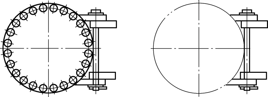
Template positioning assembly is suitable for assembly where positioning or measurement between components is difficult. For example, in the flange assembly shown in Figure 7, due to the difficulty in measuring the assembly dimensions of the cylinder section and flange pipe, and the difficulty in ensuring the stability of the assembly state, template positioning assembly is used.

(7) Mold Assembly
Mold assembly involves placing the corresponding assembly parts on an assembly mold (also known as a combination mold, composed of a mold base and various clamping and positioning supports), positioning and clamping them, and then assembling. This method is characterized by high assembly quality and efficiency, suitable for mass production. If a special mold is used, it is suitable for large-scale production.
(8) Horizontal Assembly (Flat Assembly)
Horizontal assembly involves placing components horizontally for assembly, suitable for the assembly of components with small cross-sections but relatively long lengths.
(9) Vertical Assembly (Upright Assembly)
Vertical assembly involves assembling components from top to bottom, suitable for components with small heights or large lower bases.
(10) Inverted Assembly
Inverted assembly involves assembling components by inverting them 180° from their usage state, suitable for structures with large upper volumes and box-shaped components where upright assembly is difficult to stabilize or where the upper cover plate cannot be welded.
II. Tools for Assembly
Depending on the different sheet metal structures, different assembly methods are selected, and different assembly tools are used. Table 2 shows the types and uses of tools.
Table 2 Types and Uses of Tools
Name | Diagram | Use |
Wedge Fixture | 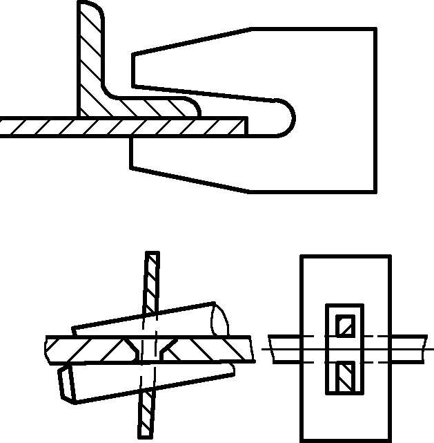 | Uses a clamp with an opening or hole and a wedge to clamp the workpiece. When the wedge is driven in, the inclined surface of the wedge generates clamping force, achieving the purpose of clamping. |
Spiral Fixture | 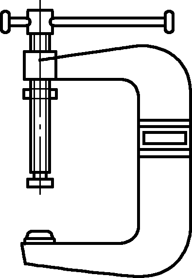 | Uses the action of a screw to perform multiple functions such as clamping, pulling, jacking, and supporting. The bow-shaped spiral fixture is a commonly used type of clamp. |
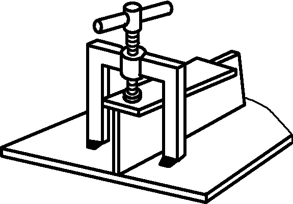 | Uses II-shaped or L-shaped iron and screws for pressing. | |
 | Uses bolts with threads in opposite directions at both ends. By rotating the bolt, the distance between the two elbows is changed, achieving the purpose of pulling. | |
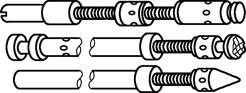 | The push rod screw has threads in both forward and reverse directions. When the screw is rotated, it can perform jacking or spreading functions. | |
Toggle Fixture | 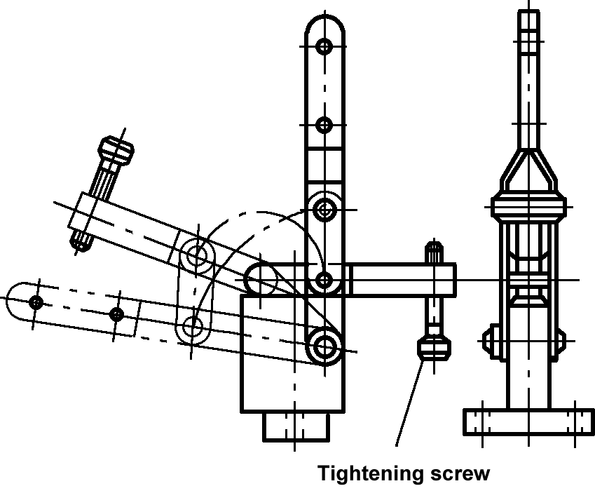 | Used for splicing medium and thin plates, characterized by quick clamping and a large range of clamping thickness adjustment. |
Eccentric fixture |  | Rotate the eccentric wheel with a handle to achieve clamping by changing the eccentric distance e. The advantage of the eccentric fixture is its quick action, but the disadvantage is its small clamping force. |
Pneumatic fixture | 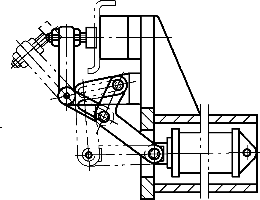 | Uses the pressure of compressed air to push the piston rod back and forth to achieve clamping. Suitable for clamping medium and thin plate components. |
Hydraulic fixture | 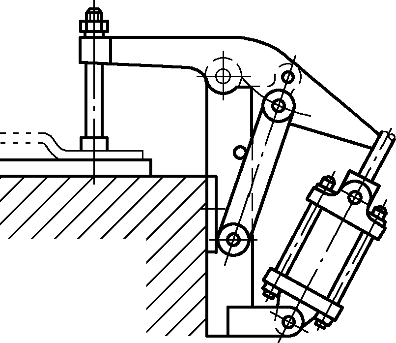 | Mainly composed of a hydraulic cylinder, piston, and piston rod. The hydraulic cylinder causes the piston rod to produce linear motion, clamping the workpiece by pushing the lever device. The advantage of the hydraulic fixture is its large clamping force and reliable operation; the disadvantage is that the liquid is prone to leakage and maintenance is inconvenient. |
Magnetic fixture | 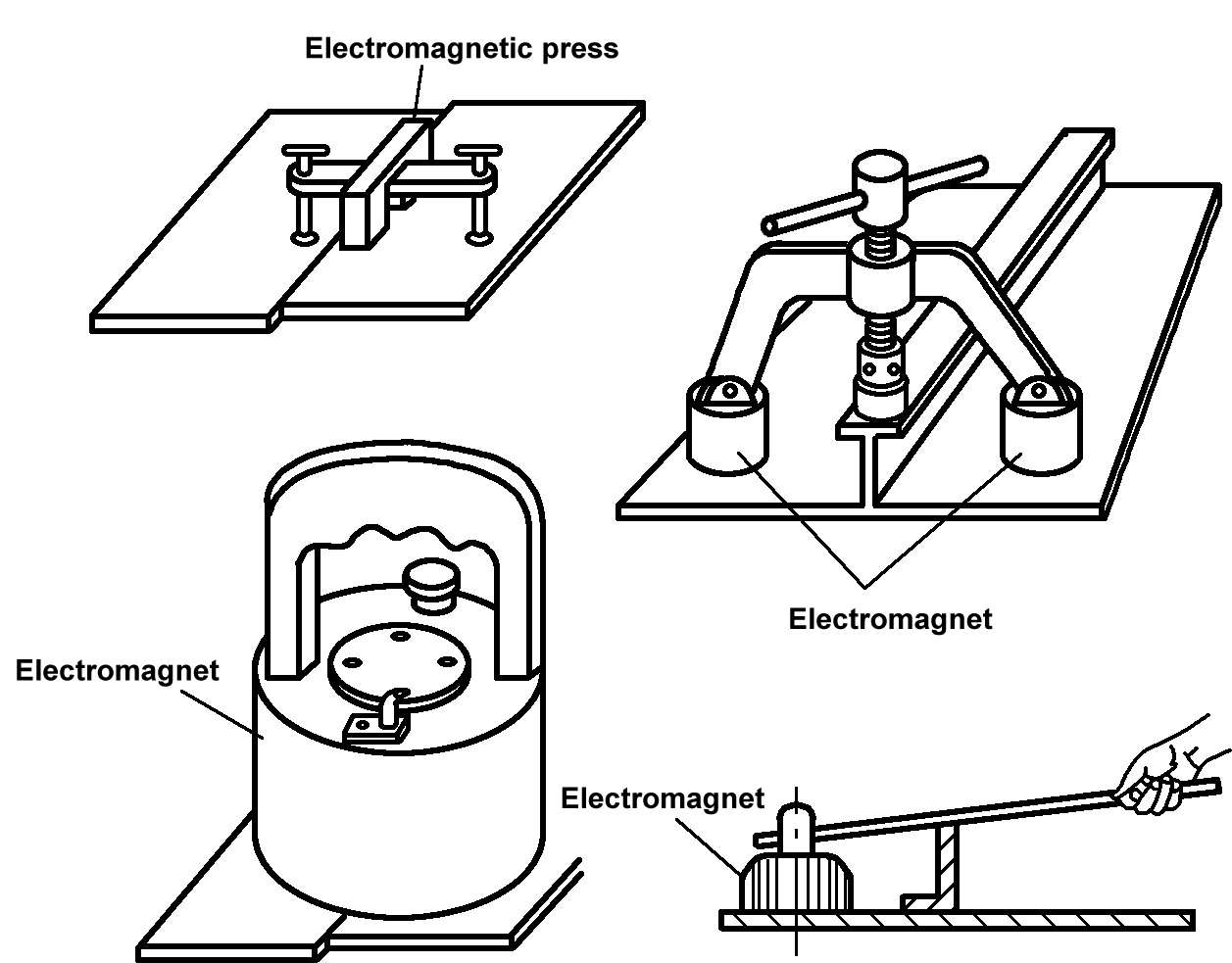 | There are two types: permanent magnet and electromagnetic. This fixture uses a magnet to hold the steel plate, relying on magnetic force or a screw or lever on the rotating press to clamp the workpiece. |
Copper hammer | 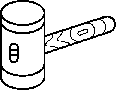 | Used for adjusting and assembling parts. |
Wooden hammer | 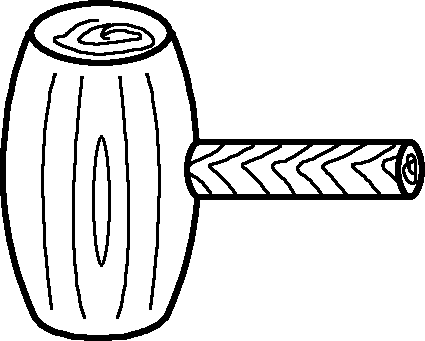 | Used for hammering thin steel plates, non-ferrous metal sheets, and sheet metal components with high surface quality requirements. |
Lever | 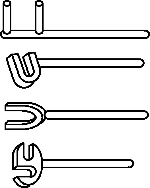 | Used for correcting and adjusting the shape of sheet metal components, and can also use the lever principle to clamp workpieces. |
Platform with T-slots | 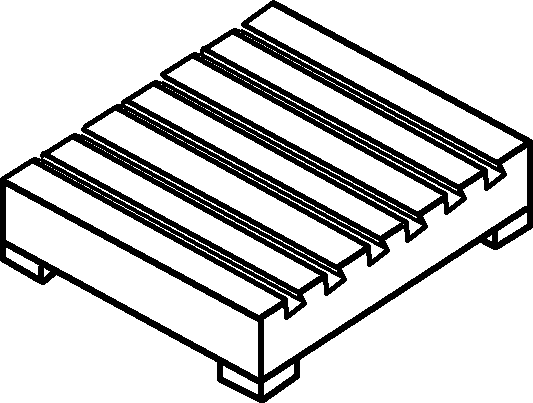 | Bolts can be inserted into the T-slots to fix workpieces, used for workpiece shaping or forming, assembly, and welding. |
Additionally, during assembly, a large number of marking tools and assembly platforms, as well as tools for supporting, adjusting, and lifting sheet metal components, will be used, which are not listed here one by one.
III. Measurement of Assembly
Measurement during assembly is an important processing content to ensure the quality of assembled components. Due to the influence of processing site, complexity of assembled components, etc., assembly measurement has some methods and means different from single part processing measurement.
1. Measuring tools and instruments
In addition to the tools and instruments used for processing single workpieces, assembly measuring tools and instruments also require tools and instruments for measuring shape and position, such as levels, plumb bobs, leveling instruments, and vertical instruments, as shown in Figure 8.

a) Plumb bob
b) Leveling instrument
c) Ordinary level
d) High-precision level
2. Measurement methods
Common measurements include surface measurement, size measurement, and shape and position measurement. Among them, the reasonable determination of the measured surface and measurement accuracy is the premise and foundation for ensuring assembly accuracy.
(1) Plane measurement
Leveling has two methods: powder line method and visual inspection method.
1) Powder line method.
The powder line method uses powder lines or steel wires for adjustment as shown in Figure 9. The thickness of the powder line or steel wire should not exceed 1mm. During leveling, the powder line is tightened, and the force on the two powder lines is kept consistent. The intersection of the two powder lines is used to determine whether the four endpoints of the two powder lines are on the same plane.

To determine whether the midpoints of the two powder lines are in contact, a conclusion should not be drawn based on a single measurement. The positions of the two powder lines should be changed several times. Regardless of which powder line is on top or bottom, the tightness after contact should be the same to finally determine the flatness of the plane being leveled.
2) Visual inspection method.
The visual inspection method is suitable for leveling rod-shaped parts or frame structures based on rod-shaped parts during single-piece assembly.
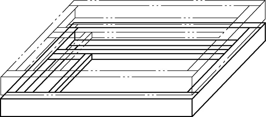
Figure 10 shows the method of measuring the flatness of a plane frame structure welded from two I-beams AB and CD using the visual inspection method. The I-beams AB and CD are used as leveling references (in the figure, for easy identification, the I-beam CD is drawn with double dotted lines). Observations are made from points B and D of the I-beam towards points A and C. If AB, CD, AD, and BC are parallel and have good straightness, the flatness of the plane frame structure can be roughly determined to be good.

The measurement accuracy of the visual inspection method is greatly affected by the observer’s position, vision, environment, and experience, but it is practical. During measurement, the observation point should not be too close to the I-beam. It is better to be farther away as long as observation is possible.
(2) Horizontal plane measurement
Common methods for horizontal plane measurement include the hose method and the level method.
1) Hose method.
The hose method involves filling a transparent hose that can communicate with water or other liquids to find the horizontal plane. It is a simple and effective method for finding planes with horizontal characteristics.
For easy observation, two liquids with contrasting colors (the contact interface of the two liquids is separated by an appropriate amount of engine oil) can be poured into the two ends of the hose, such as yellow and blue, red and green. When the measurement environment temperature is below 0°C, to prevent freezing in the hose, the water in the hose can be replaced with another liquid or antifreeze can be added to the water.
Measurement adjustment is based on the liquid level height in the hose as the reference height (see Figure 11), adjusting all parts that do not match the liquid level height until all parts that need adjustment meet the expected requirements. The hose method is especially suitable for horizontal leveling and elevation determination in complex environments with limited visibility.
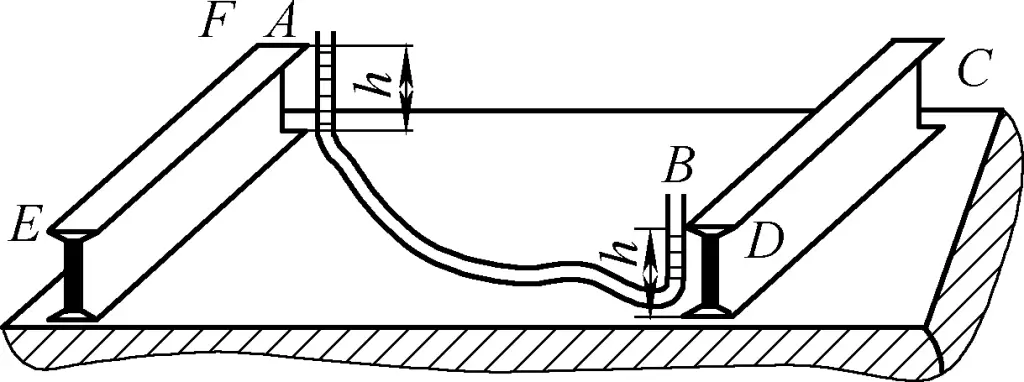
During measurement, one end of the hose is fixed at a measurement point, and the liquid level height position is marked. Then, the other end of the hose is moved, and based on the liquid level height of the movable end, the measurement point’s elevation is adjusted and determined while keeping the fixed end’s elevation unchanged. Appropriate adjustments to the liquid level height can be achieved by adjusting the length of the hose with liquid.
It is worth noting that the liquid poured into the hose has surface tension. If the hose diameter is relatively small, the liquid level is not a plane but a curved surface, especially with water, this phenomenon is particularly noticeable. To maintain observation accuracy during measurement, the observation reference surface should either take the highest position of the liquid level or the lowest position of the liquid level.
When the length of the hose with liquid in the plane part increases, the measured liquid level height decreases. The hose used for liquid level measurement should be transparent, with an inner diameter of ϕ6 to ϕ10mm being appropriate.
2) Level method.
The level method uses a level and leveling instrument to find the horizontal plane. Based on the function and accuracy of the level, it can be used for leveling horizontal, vertical, and even 45° inclined planes (see Figure 12).
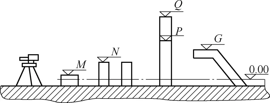
The accuracy of leveling with the level method increases with the accuracy of the level, with the square level having the highest accuracy. For installing high-speed rotating pumps, a square level with level 2 measurement accuracy should generally be used. When the measured part has a plane, the level can be directly placed on the plane for measurement adjustment.
When measuring a large spatial length with an ordinary level, a steel wire with a diameter not greater than 1mm can be used to tighten the ends of the measured surface, and the level is placed in the middle of the steel wire. The horizontal level of the steel wire ends is determined by adjusting the height of the steel wire ends. When using this method, attention should be paid to the sagging of the steel wire due to its own weight, which affects the measurement.
(3) Length measurement
When the length measured during assembly is at different elevation levels or centerlines, causing the length annotation not to be displayed on a single plane or axis, length measurement can be performed using a plumb bob in conjunction with a level, square, etc., for length measurement and conversion (see Figure 13).
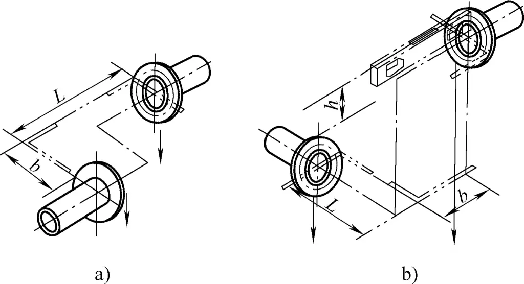
a) Measurement of centerline distance
b) Measurement of centerline distance at different elevations
(4) Height measurement
If different heights appear in the same component, they are generally measured and converted through the base elevation or other measurement elevations (see Figure 14).

a) Measurement of the height of cylindrical and conical cylinders
b) Measurement of different height connections
(5) Angle measurement
Angle measurement methods include the angle side length measurement method and the template method. When the side length of the angle is long, measuring the side length can effectively ensure the accuracy of the angle. For angle side length measurement, the Pythagorean theorem, tangent, or cotangent trigonometric functions can be directly used for calculation, as shown in Figure 15. Angle template measurement is shown in Figure 16.
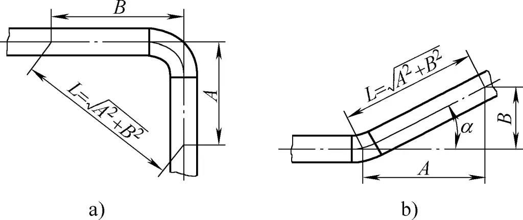
a) Right angle length measurement
b) Acute angle length measurement

a) Using vertical as a reference
b) Using horizontal as a reference
(6) Gap measurement
Often used for measuring weld gaps, generally using a special weld gap caliper, as shown in Figure 17.

(7) Verticality measurement
Verticality measurement includes vertical and inclination measurement. Common tools for measuring verticality and inclination include plumb bobs, levels, and vertical instruments. Vertical instruments are suitable for determining vertical accuracy at higher heights.
For the plane assembly of pyramid-shaped frame structures, the inclination measurement is shown in Figure 18. During assembly, the inclination can be adjusted to perform the measurement.

Inclination measurement can also be performed using a plumb bob, as shown in Figure 19. The inclination angle α measured by the plumb bob can be calculated using α=arctanH/B′.

(8) Levelness measurement
For the measurement of levelness, refer to the measurement of planes.
(9) Measurement of straightness
The straightness measurement of spliced components can use a steel ruler or the wire method (see Figure 20). The wire method is mainly suitable for measuring the non-straightness of cylindrical sections and rod-like parts with a large length-to-diameter ratio.

(10) Measurement of concentricity
Concentricity measurement includes the measurement of equal diameter concentricity and unequal diameter concentricity. For the measurement of different diameter concentricity, the method of sectional assembly with internal wire measurement should be adopted, as shown in Figure 21a.
For cylindrical bodies with different diameters as shown in Figure 21b, they should be divided into three parts: the straight cylindrical section in the middle, the straight cylindrical sections at both ends, and the conical body. Each part’s straightness and concentricity should be measured separately. Once each part’s concentricity meets the relevant regulations, they can be assembled and measured together.
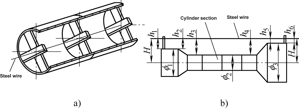
a) Internal wire method for measuring concentricity
b) External wire method for measuring concentricity
(11) Measurement of diagonal deviation
The measurement of diagonal deviation is an indispensable method and procedure in assembly measurement. Especially when assembling a frame on a leveled, but not horizontal, plane, ensuring the overall shape and position is entirely achieved through the measurement and control of diagonal deviation.
Moreover, for right angles on a rectangular plane, the effect of using the diagonal measurement method is incomparable to horizontal or vertical measurement methods. Additionally, in the diagonal measurement during the overall assembly of a rectangular frame structure, using diagonal measurement is an extremely effective method to ensure the overall shape and position deviation.
Diagonal measurement can be used to check the shape and position deviation of various shaped blanks. Depending on the specific situation, it is divided into two types: equal diagonals (see Figure 22a-e) and unequal diagonals (see Figure 22f).
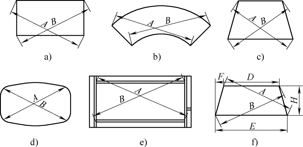
a) Rectangle
b) Sector
c) Isosceles trapezoid
d) Segment of a spherical tank
e) Angle steel frame
f) Ordinary trapezoid
For axially symmetric blanks, the two diagonals should be equal, and their unequal deviation should meet the relevant technical requirements. For the diagonals of an asymmetric ordinary trapezoid (see Figure 22f), their lengths are unequal. The lengths of the two unequal diagonals can be calculated using the following formula:
A=√[(E-F)2+H2]
B=√[(F+D)2+H2]
IV. Operations of typical sheet metal assemblies
Most sheet metal assemblies are single-piece or small-batch productions, involving many trades. The assembly process often involves a lot of welding or other connection processing, which can easily cause post-weld deformation. Therefore, measurements should be done before assembly, and corrections and shaping should be done after assembly. During assembly, adjustments to the dimensions and positions of the assembled components should also be made.
During assembly, a sturdy and stable assembly site should be chosen. The flatness of the cast iron or cast steel platform used for welding assembly should be ≤1mm/m2, the flatness of the entire platform should be ≤1.5mm/m2, and the flatness of a platform assembled from more than two platforms should be ≤2mm/m2.
During assembly, the measuring, auxiliary, and lifting tools used should ensure safety, accuracy, and reasonable use. The following describes the operation techniques using several typical sheet metal assemblies as examples.
1. Operation techniques for assembling large cylindrical parts
Large cylindrical bodies are usually welded from multiple cylindrical sections. Therefore, their assembly actually includes the welding of individual cylindrical sections (mainly longitudinal seam welding) and the assembly of cylindrical sections (mainly circumferential seam welding).
(1) Assembly of longitudinal seams
Cylindrical sections are usually manufactured and shipped as a whole, so the assembly of longitudinal seams is generally completed during the forming process.
After the cylindrical body is rolled and bent, its longitudinal seam cannot be perfectly correct. When the cylindrical wall is relatively thin and the diameter is large, it may become elliptical due to the weight of the cylindrical body. Additionally, there are issues such as misalignment, uneven edges, and uneven gaps.
Therefore, before welding the longitudinal seam, various defects need to be corrected or adjusted. After welding, any significant roundness differences should be corrected. For specific operation methods, refer to the relevant content of the “cylindrical rolling operation techniques.”
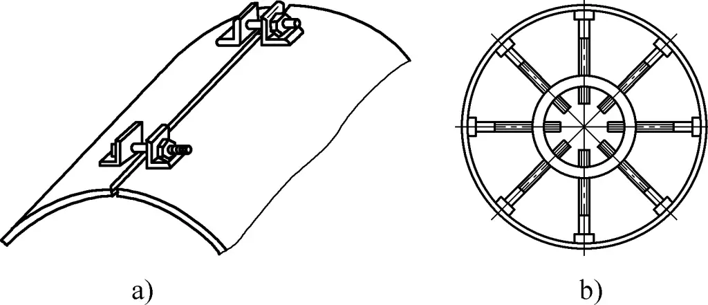
Figure 23 shows several methods for aligning the edges of cylindrical bodies. Figures 24a and 24b show commonly used methods in production for adjusting the longitudinal seam of a cylinder using a spiral tensioner and eliminating the oval shape of a thin-walled cylinder using a ring-shaped pusher.
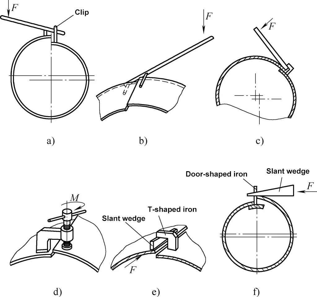
a), b), c) Using a lever
d) Using a spiral press
e) Using a wedge press
f) Using a portal iron
(2) Assembly of circumferential seams
When the cylindrical body is relatively long and consists of several cylindrical sections connected or has end caps installed at both ends, there will be circumferential welds at the joints. To ensure that the connected cylinders are on the same centerline and that the circumferential welds of the end caps meet the technical requirements of the drawings, effective assembly operations must be performed on the circumferential seams. The assembly of cylindrical body circumferential seams is divided into horizontal and vertical methods.
Vertical assembly is more convenient than horizontal assembly and does not require a large site, but it has certain requirements for lifting height. The specific method to use depends on the maximum lifting height and maximum lifting tonnage of the crane. If conditions permit, vertical assembly should be used as much as possible.
1) Horizontal assembly
The forms of cylindrical bodies in horizontal assembly are diverse, including large and small diameters, thick and thin plates, and two-section and multi-section assemblies. Regardless of the form of circumferential seam assembly, to ensure that the participating cylinders are concentric and facilitate the rotation of the cylindrical body, assembly work is often carried out on a roller stand.
Figure 25a shows a manual roller stand. To ensure the concentricity of the assembled cylinders, the diameter of each roller on the roller stand must be equal, and the lateral distance and height position of each pair of rollers must be the same. This ensures that each roller is on a horizontal plane.
Due to the large weight of the cylindrical body itself, no external force is needed to clamp it during assembly. The rotation of the cylindrical body can be done manually or with the help of a lever. For larger or longer cylindrical bodies, to reduce the labor intensity of manually rotating the cylindrical body during assembly, a motor-driven roller stand can also be used.
If the diameter of two cylindrical sections is not large but the length is long, to prevent the cylindrical sections from bending due to their own weight, more support rollers are required. However, the more rollers there are, the more difficult it is to ensure they are on the same horizontal plane. Therefore, when connecting slender cylindrical sections, a roller stand composed of two rigid round steel pipes, as shown in Figure 25b, can be used for assembly (the rollers themselves can rotate).
If there is little rotation during assembly, a mold composed of two round steel pipes (see Figure 25c) or two straight steel sections can be used instead of rollers (see Figure 25d).

For the assembly of multi-section large-diameter cylindrical bodies, motor-driven roller stands are often used in combination with manual roller stands.
Using the above roller stands for assembly can prevent the entire cylindrical body from bending. However, when there are diameter deviations or local defects around the cylindrical body, it is not possible to ensure that the entire cylindrical body is concentric and that the interfaces completely match. In such cases, adjustments must be made during assembly. If there is a diameter deviation between two cylindrical sections, the section with the smaller diameter should be elevated during assembly to ensure uniform wall thickness deviation and achieve concentricity.
① Principles of horizontal assembly.
During horizontal assembly of the cylindrical body, the assembly of each component should be based on the principle of aligning the elliptical shapes formed by the cylindrical body, ensuring that the long axis aligns with the long axis and the short axis aligns with the short axis. This way, even if the ellipticity is large, it will not affect the assembly; conversely, even if the ellipticity is small, it is not conducive to assembly.
Figure 26a shows the correct assembly method, where two small cylindrical sections are placed on a motor-driven roller stand and a manual roller stand, respectively. Since each rotating stand can ensure equal height and equal span, and the force direction is the same, forming a unidirectional ellipse, the misalignment is small, ensuring the assembly installation requirements.
Figure 26b shows the incorrect assembly method, where one cylindrical section is placed on a motor-driven roller stand, and the other is suspended by a crane. The different force directions form bidirectional ellipses, with the former forming an ellipse with the long axis in the horizontal direction and the latter forming an ellipse with the long axis in the vertical direction. The misalignment is large, making assembly difficult, and thus it is difficult to ensure assembly quality.

② Layout and design of assembly molds.
Based on practical experience, the active mold must be placed in the middle (see Figure 27a) and not at the end, because the weight at the end is too small, resulting in insufficient pressure and too little friction, making it difficult for the cylindrical body to rotate.
The design of the mold mainly involves designing its height and span. Under the premise of ensuring equal height of each rotating stand, the span must also be equal. This ensures that the ellipticity formed at both ends is basically the same. The span angle is 45° to 60° (see Figures 27b, 27c). The inspection method can use a combination of ruler measurement and line drawing to ensure that each mold is of equal height, equal span, and parallel.

The main lifting methods for cylindrical bodies are shown in Figure 28, where Figure 28a shows double-rope lifting, Figure 28b shows single-rope locking lifting, and Figure 28c shows lifting with lifting lugs and chain blocks. The specific method to use should be determined based on the specific situation.

③ Adjustments in horizontal assembly.
During the assembly process of the cylindrical body, adjustments are often needed due to defects such as ellipticity, misalignment, and uneven gaps. The main adjustment methods are as follows.
Method for adjusting ovality. Figure 29 shows common methods for adjusting ovality. Figure 29a shows the chain block method, where two lifting lugs are welded in the direction of the maximum major axis. By applying force through ropes, the major axis shortens and the minor axis lengthens, thus adjusting the ovality. Figure 29b shows the jack method, where a jack and a push rod are placed on the maximum minor axis. After applying force, the minor axis expands and the major axis shortens, thus adjusting the ovality.
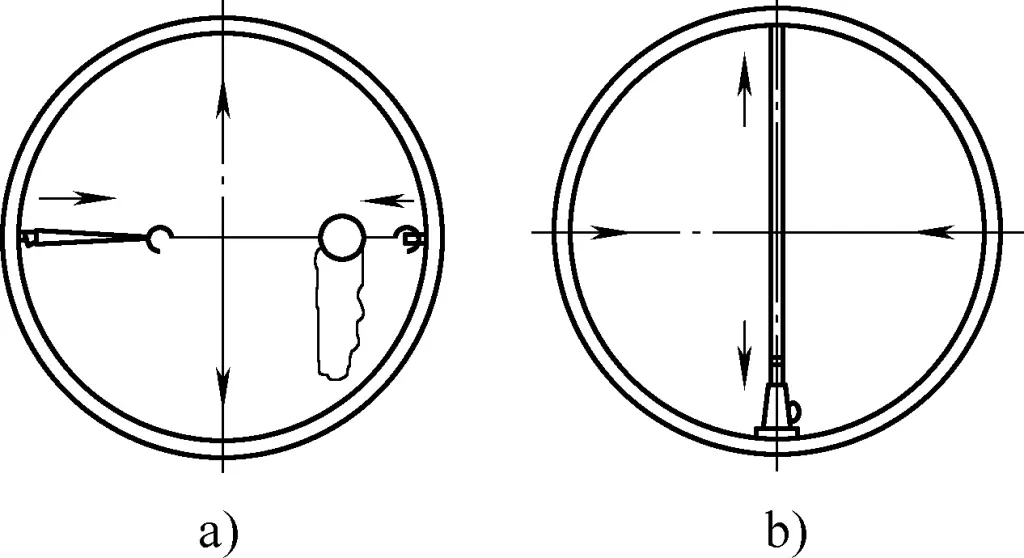
Methods for handling uneven gaps. Figure 30 shows common methods for handling uneven gaps. When the gap at the lower or horizontal position is suitable but the upper gap is large, a spot weld can be placed at the suitable gap, and then the crane’s lifting force can be used to reduce the upper gap, as shown in Figures 30a and 30b. When the middle gap is suitable but the lower gap is large, a spot weld can be placed at the suitable gap, and then a jack or crane can be used to reduce the lower gap, allowing the upper gap to naturally expand, as shown in Figures 30c and 30d.

Methods for handling large gaps in the middle range. For defects with large gaps in the middle range, the chain block method can be used, as shown in Figure 31.

Methods for handling small gaps in the middle range. For small gaps in the middle range, positioning welding fixtures can be used first, then tools like jacks and wedges can be used to expand the gap. Figure 32a shows the jack method, Figure 32b shows the wedge method, and Figure 32c shows the forward and reverse screw rod method (the threads at both ends in the figure are in opposite directions).

Methods for handling misalignment. In addition to rotating the cylinder and adjusting the crane’s lifting force and position to adjust misalignment, the methods shown in Figure 33 can also be used. Figure 33a shows the wedge method, Figure 33b shows the jack method, Figure 33c shows the spiral press horse method, and Figure 33d shows the wedge plus press horse method.

Methods for ensuring offset amount. Due to differences in processes such as cutting, rolling, and welding, the circumferences of the end faces of the cylinder ring seams may not be equal, resulting in an offset amount.
Therefore, before assembling the cylinder, the circumferences on both sides of each ring weld seam of the cylinder should be measured to determine their respective unfolded length deviations, which are then converted into diameter deviations to find the range of offset amounts. By adjusting the offset amount, these deviations can be evenly distributed around the circumference (see Figure 34a). The methods for adjusting the offset amount are shown in Figures 34b and 34c. Figure 34b shows the wedge adjustment method, and Figure 34c shows the bolt adjustment method.

2) Vertical assembly
Vertical assembly not only has the advantage of occupying a small site area but also allows for easy observation of defects displayed around the cylinder and facilitates handling. When using vertical assembly of the cylinder, lifting equipment is generally required to assist with assembly, and some simple and lightweight auxiliary tools are also needed for coordination.
① Methods of alignment.
There are roughly three methods for vertical alignment: one is the inclined wedge alignment method, the second is the four-point fixation method, and the third is the comprehensive treatment method. The choice of method depends on the diameter and plate thickness of the cylinder.
Inclined wedge alignment method. Figure 35 shows a schematic of the inclined wedge alignment method. This method is generally suitable for cylinders with smaller diameters and thinner plates. It is usually not necessary to measure the circumferences of both ends or calculate the misalignment amount. As long as the misalignment amount and gap are adjusted to be equal in one go, positioning welding can be performed to fix it.
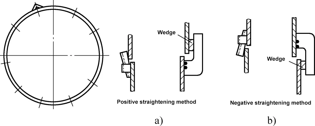
The positive correction method (see Figure 35a) is generally used because it is convenient for hammering to apply force for correction. Only in individual dead-end areas is the reverse correction method (see Figure 35b) used, as the reverse correction method is not convenient for hammering to apply force. It should be noted that one should not use the positive correction method just because the upper end is high, or the reverse correction method because the lower end is high, as correcting the upper height will inevitably reduce the lower height at that point.
Four-point fixation method. The four-point fixation method involves measuring the outer circumference of the upper and lower ends and dividing it into four equal parts, marking the degree of each division, and then manually prying to align the corresponding degree lines. After positioning welding to fix the four degree lines, positioning welding is performed in each section according to the predetermined misalignment amount (see Figure 36). This method is mostly used for thin-walled cylinders with low rigidity, as they are easy to pry and shift.

Comprehensive treatment method. The comprehensive treatment method starts from the first positioning weld point and proceeds sequentially along one side or alternately along both sides (depending on the fit) according to the predetermined misalignment amount for positioning welding.
Use a ruler method, visual inspection, or tactile method to ensure the misalignment amount. When positioning welding reaches 1/2 or 2/3 of the circumference, the remaining circumference’s misalignment amount is re-determined, and positioning welding continues according to this misalignment amount or is handled using the inclined wedge alignment method, as shown in Figure 37.

1—Starting fixation point
2—End point of the first positioning weld
② Adjustment of vertical assembly.
The same cylinder often requires adjustment for defects such as misalignment, excessive or insufficient gaps during vertical alignment of ring seams. The main adjustment methods are as follows.
Methods for handling various defects using a crane. Adjusting the crane’s position and lifting force can adjust all alignment defects. The up and down movement of the hook can adjust the gap size, and the left, right, front, and back movement of the hook can adjust the misalignment. The effect will be better when combined with flexible use of fixtures, as shown in Figure 38.

Methods for handling misalignment. Misalignment can be handled using the methods shown in Figure 39. Figure 39a shows the use of a wedge iron for lifting pressure, or using a flat-nosed iron to pry, or using both. Figure 39b shows the spiral press horse lifting pressure method, which is simple and easy to implement, requiring only the front end of the base plate to be positioning welded to fix the base.
Figure 39c shows the use of a flat-nosed small crowbar for lifting pressure, mainly suitable for handling thin-walled and small misalignment cylinders. Figure 39d shows the wedge plus press horse method, which is simple to operate and has good handling effects.

Methods for ensuring uniform and consistent gaps. Whether in horizontal or vertical alignment, the circumferential gap should be uniform first to ensure straightness. Therefore, the welding method used should ensure the necessary gap.
For example, when using electrode arc welding, a gap of 3-5mm should be left for penetration. Before positioning welding, a ϕ3.2mm electrode should be used as a feeler gauge, and positioning welding can only be performed after passing inspection. When using submerged arc welding, due to its high penetration capability, no gap is needed. When uneven gaps occur, the crane’s lifting force should be used to adjust at the beginning of positioning welding. If adjustment is made after positioning welding reaches half the circumference, the effect will not be significant.
Therefore, from the start of positioning welding, attention should be paid to the uniformity of the gap. If inconsistency in the gap occurs after positioning welding reaches half the circumference, and adjusting the crane’s lifting force is ineffective, the following methods can be used: chain block gap reduction method, jack method, wedge method, and forward and reverse screw rod method.
Finally, when small range gaps or misalignments do not meet requirements, the only remedy is to grind or cut open many weld points, allowing more circumference to participate in the distribution of the misalignment amount until the misalignment amount is within tolerance. Then, complete the positioning welding according to the newly determined misalignment amount and gap.
2. Assembly of spherical cap into cylindrical parts
According to the forming and processing principles of cylindrical bodies, regardless of size or thickness, cylindrical bodies undergo significant deformation after rolling and welding. Even after round correction, their cross-sections may not be perfect circles. In fact, the processing accuracy of various sheet metal components is not high, and most assemblies require adjustments to be completed.
There are generally two methods for assembling spherical caps into cylindrical bodies: one is the covering method, where the head is cut to the net material (4mm smaller than the design diameter). The prerequisite for this method is that the distance from the alignment ring seam should preferably be greater than 1000mm. Before insertion, the ovality of the cylinder must be corrected to within tolerance. The second method does not consider the cylinder’s roundness and cuts it into a perfect circle 4mm smaller than the design diameter, with corresponding measures taken during subsequent assembly and welding.
Figure 40 shows the construction drawing of the spherical cap inside the cylinder. The following introduces the assembly operation techniques through this example.
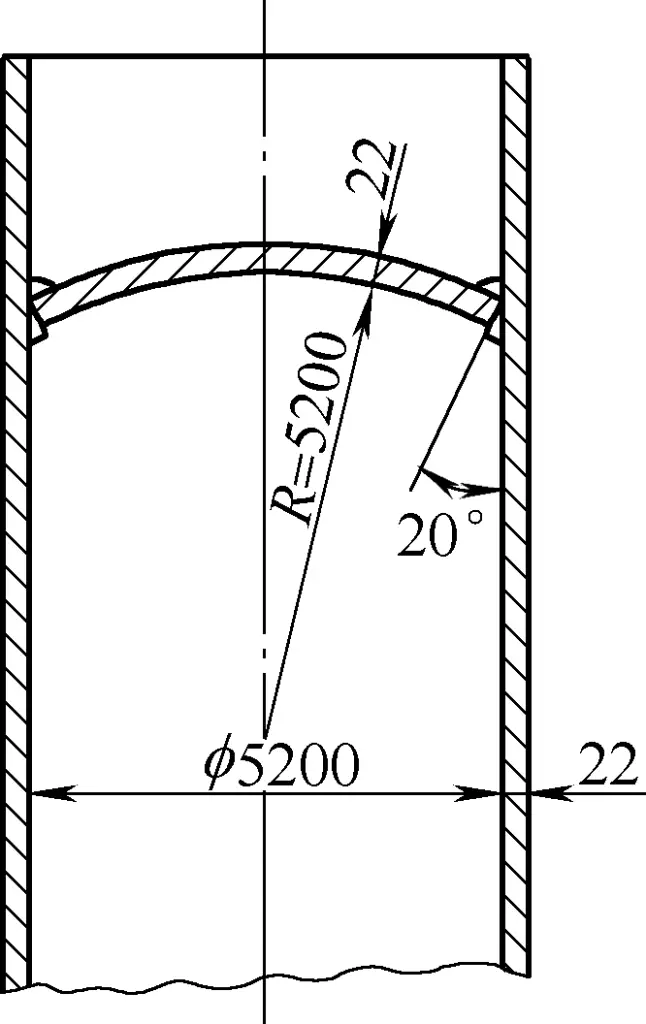
(1) Covering method for cutting head net material
All curved surface heads need to leave enough allowance for cutting because after cutting, they need to undergo splicing, alignment, and pressing. If there are errors during splicing, the errors will be greater during pressing, such as being too deep or too shallow, having too large or too small curvature, being stretched or compressed to different extents, etc. Additionally, differences in material and heating temperature will affect the cutting accuracy, so enough allowance should be left for secondary cutting after pressing and forming.
1) Marking method.
Figure 41 shows the method for cutting using the covering method. When arranging ring seams, the distance between the head ring seam and the cylinder ring seam should be as large as possible, generally greater than 1m. If too close, the rigidity will be too high, affecting the alignment of the cylinder ring seam.

1—Lifting lug
2—Spherical cap
3—Cylinder
4—Platform
5—Long stone pen
After the rounded head is lifted onto the cylinder to be inserted, use a flat-nosed long stone pen to carefully mark along the inner wall of the cylinder (it is better to cut on the inside of the line). After marking, corresponding position marks should be made for both, and after lifting, insert according to the corresponding marks, minimizing misalignment.
2) Arrangement of lifting lugs.
Since the head is circular, the horizontal and vertical coordinates of the four lifting lugs should be equal. The purpose of setting four lifting lugs is to balance the head during lifting and allow for independent fine-tuning of any position. The arrangement of the lifting lugs is shown in Figure 42.

3) Cutting method.
Figure 43 shows a schematic of the manual cutting method. Place the head with the marked cutting line facing up on a cylinder to increase its stability and make it roughly level. During cutting, tilt the cutting nozzle inward at an angle (about 20°) to meet the design bevel requirements.

(2) Direct cutting into a perfect circle method
Cutting directly into a perfect circle means not considering the roundness of the cylinder, cutting it into a perfect circle with a size less than 4mm of the design diameter. It is 4mm smaller than the design diameter, leaving a 2mm gap on each side. Although this gap is predetermined, since the cylinder may not be a perfect circle, it might not fit due to excessive ovality. In this case, a chain block can be used to reduce the long axis and increase the short axis to make it fit.
After fitting, some areas may have no gap, while others may have gaps too large to weld. In this case, besides continuing to use a chain block to adjust the gap, wedge iron can also be used to adjust it, ensuring the largest gap is weldable.
The method of cutting into a perfect circle with a circle cutter is shown in Figure 44. After marking the line on the ground, air gouging can be used for cutting, allowing the cutting nozzle to tilt outward to cut the bevel angle in one go, or the cutter can be used for vertical cutting followed by additional beveling.
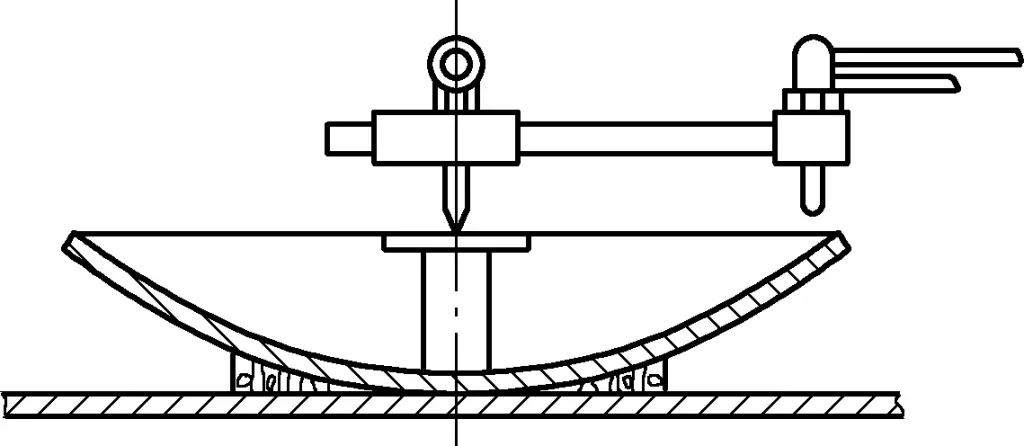
(3) Methods for assembly adjustment
According to design requirements, mark the position line of the head on the inner wall of the cylinder, then the cut head can be hoisted into the cylinder for assembly. During assembly, the convex side can face up or down, but it is better to have the convex side down. This is because it is easier to align with the position line, adjust defects, and perform tack welding.
During welding, a tack weld can be made at the line position first, then subsequent welding can continue. During assembly, various defects can be handled using the following methods.
1) When starting to assemble and weld, it may not fit smoothly due to excessive ovality, so the ovality should be adjusted before fitting. Figure 45a shows the method of using a chain block to adjust large gaps and ovality, i.e., pulling closer in the long axis direction to reduce the large gap area.
In addition, due to local excessive ovality, it may still not fit smoothly. Figure 45b shows the method of using wedge iron to adjust entry defects, i.e., reducing the area with large coverage through the action of wedge iron to make it fit.
2) When the head position is slightly too high, it can be adjusted by hammering with a sledgehammer; when it is significantly too high, it can be pressed down using the wedge iron method shown in Figure 45c or adjusted using the chain block method shown in Figure 45d.

1—Adjust large gaps
2—Adjust ovality before fitting
3) When the head position is too low, it can be lifted using the eccentric lifting method to align with the marked line before fixing with tack welding, as shown in Figure 45e.
4) If the assembly gap is too small and difficult to move, gas cutting can be used for micro-cutting.
5) If the local gap is too large after assembly, making welding impossible, the chain block method can be used to pull the diameter with the large gap closer, reducing the gap, while the small gap area will also expand.
3. Assembly of spiral staircases for storage tanks
The spiral staircase is an accessory on the storage tank, with a cylindrical spiral structure. The production of the spiral staircase mainly includes three aspects: first, the calculation of the expanded size of the spiral staircase, second, assembly welding, and third, installation.
The correct calculation of the expanded size of the spiral staircase is the premise to ensure the quality of the structure, and assembly welding is the main factor to ensure installation. Therefore, before cutting the spiral staircase, the drawing dimensions should be carefully checked, and the accurate expanded size should be calculated through layout, while mastering the correct assembly method to ensure assembly quality.
(1) Expanded cutting
In terms of the structure of the spiral staircase, the center lines of its two side plates and the center line of the tread plate can be imagined as a right helical surface. The center line of the tread plate is the generatrix of the helical surface. The expansion of the right helical surface is a circular ring surface larger than the radius of the storage tank, which is the forming arc radius during the assembly of the spiral staircase.
The spiral staircase of the storage tank is shown in Figure 46. In the plan view, the angle α contained in the spiral staircase is called the wrap angle of the spiral staircase, H is the height of the spiral staircase, and L is the arc length contained in the range of angle α on the center line of the spiral staircase. Since the rise angle of the center line of the spiral staircase is constant, its center line should be expanded into a straight line.
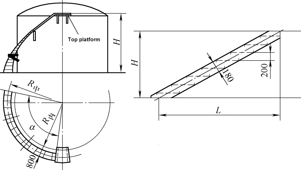
The center line of the tread plate should meet two conditions: first, each center line in the plan view should be on the radial line passing through the center of the tank, and second, the two ends of the center line of the tread plate should be on the center line of the inner and outer side plates and on the same horizontal plane. Therefore, the three center lines of the side plates and the tread plate are the main data for expanded cutting and assembly of the spiral staircase. The expansion and marking of the side plates of the spiral staircase are shown in Figure 47.
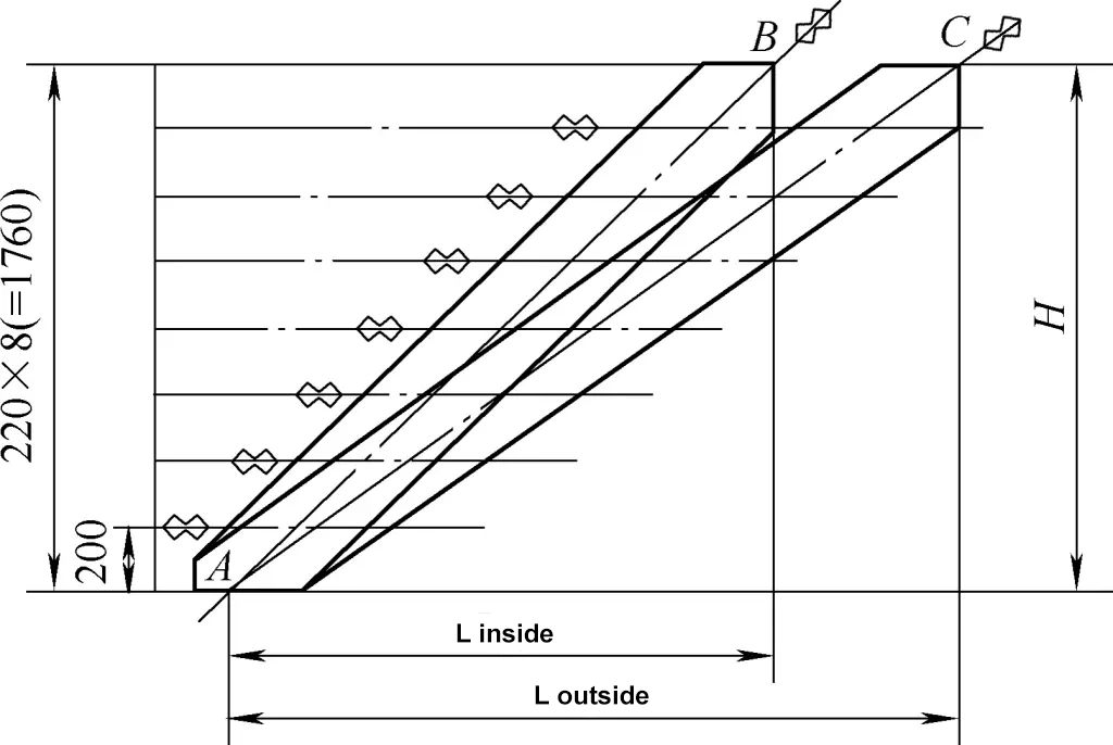
Among them, Linner and Louter are the plane arc lengths of the center lines of the inner and outer side plates within the wrap angle range, H is the height of the spiral staircase, and AB and AC are the expanded lengths of the center lines of the inner and outer side plates. The calculation formulas for parameters such as Linner, Louter, H, and α can be found in the rolling bending operation techniques of spiral components.
According to the required width of the side plates in the drawing (generally about 180mm), mark the edge lines of the side plates on both sides of the center line, and the joint template of the inner and outer side plates can be marked.
Divide the height H of the spiral staircase equally according to the height between every two tread plates (generally 200-240mm), and draw horizontal lines. The line segments obtained on the side plates are the assembly center lines of the tread plate and the inner and outer side plates. The height of the upper and lower ends should be adjusted according to the connection with the platform, which should be particularly noted during the layout and manufacturing of the spiral staircase.
(2) Assembly welding
After the tread plate of the spiral staircase is pressed and formed, it can be assembled. Before assembly, the two side plates should be straightened, as unstraight side plates will affect the accuracy of marking and assembly. If conditions permit, the side plates can be rolled on a rolling bed according to the vertical direction after forming.
Mark the assembly lines of the tread plate on the inner and outer side plates according to the layout dimensions, as shown in Figure 48a. Generally, assembling the outer side plate first is less labor-intensive than assembling the inner side plate first. After positioning and welding the center plate on the outer side plate according to the line, use a bending ruler to ensure the tread plate and side plate are vertical, and fix all the tread plates with tack welding from the center to both sides.
Then stand the side plates up, and still fix the tread plates with tack welding from the center to both sides according to the line. During the tack welding process, use clamps to fix the side plates into a circle on the forming arc line, and ensure the center line of the tread plate is on the radial line of the arc radius, as shown in Figure 48b.

1, 5—Center line of the tread plate
2, 6—Tread plate
3, 7—Side plate
4—Center line of the side plate
8—Fixing clamp
The assembly mold can adopt the form shown in Figure 49 or other forms.

After the entire forming, the diagonal of the spiral staircase can be padded to give the spiral staircase a certain twist, and then welding can be performed. The reverse side is welded with the same operation. To ensure the spiral staircase is easy to form and accurate during installation, the handrail of the spiral staircase is generally installed after the spiral staircase is in place.
(3) Installation
The installation of the spiral staircase generally involves fixing the upper part with a steel wire rope and adjusting the lower part with a chain block, as shown in Figure 50.

During hoisting, first assemble the two side plates at the top with bolts. During assembly, the cooperation of a crane and a chain block can be used to insert the bolts at the top, and then use the chain block to gradually position the spiral staircase. As long as the cutting size and assembly are correct, after the top is in place, the spiral staircase can naturally twist into shape and position due to the stress formed by welding as the chain block gradually lowers.
4. Assembly of spherical tanks
The division of the appearance of spherical tanks is the same as that of a globe, which can be divided into equatorial bands, two temperate zones, and polar regions. A complete spherical tank often requires multiple spherical segments to be connected and welded together.
Different sizes and uses of spherical tanks have different support methods, including support columns at the equatorial position and supports at the bottom of the spherical tank. Due to the large diameter of spherical tanks, their turning, hoisting, and transportation during installation are very difficult, so the bulk method is generally used for installation.
Although the assembly procedures for spherical tanks of different diameters and support methods vary, the assembly process is generally consistent. The general assembly of spherical tanks follows the process of: foundation assembly → scaffolding erection → assembly of support columns (or supports) → spherical tank assembly → inspection → heat treatment → assembly of various accessories of the spherical tank (such as spiral staircases, railings, etc.) → testing.
Figure 51 shows the inspection items and methods for the foundation of a certain spherical tank. For the foundation of a spherical tank with support columns at the equatorial position, the geometric dimensions, elevation, anchor bolts, etc., of each part of the spherical tank foundation should be checked according to design requirements before the support columns are hoisted. Only after passing the inspection can hoisting proceed.
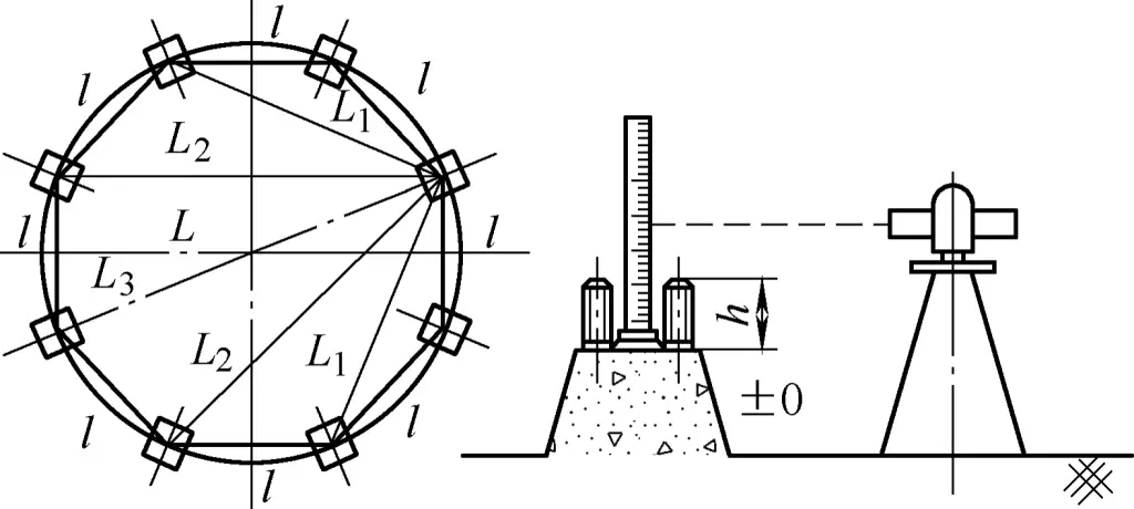
Table 3 shows the inspection items and tolerances for the foundation of a spherical tank. Similarly, the foundation supported by the bottom position of the spherical tank must also be inspected before proceeding to the next process.
Table 3 Inspection items and tolerances for the foundation of a spherical tank (unit: mm)
| Inspection items | Tolerances | Remarks |
| Distance between anchor bolts | ±2 | — |
| Chord length between support columns | ±1 | l |
| Radial chord length between support columns | ±2 | L1~4 |
| Diameter length between support columns | ±3 | L |
| Levelness of the support column foundation surface | ±2 | — |
| Effective length of bolts | 0~+2 | h |
(1) Methods for assembling spherical tanks
Although spherical tanks are installed using the bulk method, the assembly methods vary depending on the diameter of the spherical tank. Generally, there are three methods: band assembly method, hemisphere assembly method, and segment assembly method.
1) Band assembly method
Split band assembly, also known as ring band or segmented assembly. It involves dividing the entire sphere into five parts: equatorial band, upper temperate zone, lower temperate zone, upper polar cap, and lower polar cap. First, the sphere petals are welded into these five parts on the ground platform, then the upper and lower temperate zones and polar caps are assembled on the platform at the site, temporarily supported, and the sphere tank pillars and bands are welded.
This method is suitable for the overall assembly of small and medium-sized sphere tanks with a diameter of less than 12m. The process of split band assembly is shown in Figure 52, and the process regulations for segmented assembly of sphere tanks are shown in Table 4.
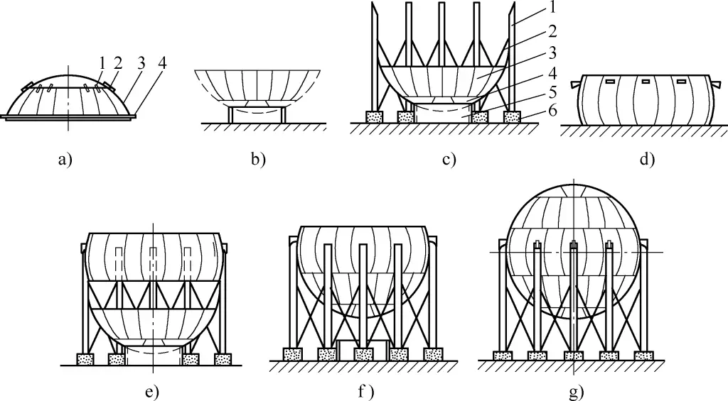
a) Lower section assembly
b) Lower section placed at the center of the foundation
c) Part of the column foot fixed to the foundation
d) Middle section of the equatorial band
e) Column foot and equatorial assembly
f) Lower section and equatorial assembly
g) Upper section and equatorial assembly
a) In the figure:
1—Polar cap
2—Reinforcement plate
3—Temperate zone
4—Reinforcement hoop
c) In the figure:
1—Column foot
2—Tie rod
3—Lower temperate zone
4—Lower polar cap
5—Ring plate frame
6—Foundation
Table 4 Process regulations for segmented assembly of sphere tanks
| Serial number | Process content | Equipment |
| 1 | Segment pre-assembly: ① Pre-assembly of equatorial band; ② Pre-assembly of upper and lower temperate zones; ③ Pre-assembly of upper and lower polar caps and fixed with reinforcement plates, positioning welding | Assembly platform, 50t truck crane, AX—320 welding machine |
| 2 | Upper and lower section assembly: ① Assembly of upper polar cap and upper temperate zone; ② Assembly of lower polar cap and lower temperate zone | Assembly platform, 50t truck crane, AX—320 welding machine |
| 3 | Welding: ① Longitudinal and circumferential seam welding of upper and lower sections; ② Longitudinal seam welding of equatorial band | CO2 welding machine |
| 4 | Lower section installation: Hoist the lower section to the installation center, flip and place on the pad, ensuring the interface end face is horizontal | 127t truck crane, level measuring instrument |
| 5 | Column foot installation: First install 5 column feet at intervals, adjust verticality, and tighten anchor bolts | 120t truck crane, level measuring instrument |
| 6 | Equatorial band and column foot assembly: ① Slowly hoist the equatorial band in balance, weld with the erected column feet, maintain the level of the upper and lower ports; ② Then install the remaining 5 column feet, adjust verticality and position weld with the equatorial band | 120t truck crane, level measuring instrument, AX—320 welding machine |
| 7 | Lower section and equatorial band closure: Hoist the lower section to close with the lower port of the equatorial band, after the circumferential seam meets the requirements, use a clamp to connect and fix, and perform positioning welding | 120t truck crane, level measuring instrument, AX—320 welding machine |
| 8 | Upper section and equatorial band closure: Hoist the upper section to close with the upper port of the equatorial band, after the circumferential seam meets the requirements, perform positioning welding | 120t truck crane, level measuring instrument, AX—320 welding machine |
| 9 | Welding: Upper and lower circumferential seams of the equatorial band, inner and outer seams | CO2 welding machine |
| 10 | Weld inspection: Radiographic and flaw detection inspection and surface weld inspection | Ultrasonic flaw detector, X-ray machine |
| 11 | Hydrostatic test | Water pump truck |
2) Hemisphere assembly method
The hemisphere assembly method involves prefabricating two hemispheres and then hoisting them into a complete sphere on site. This method is suitable for the assembly of small and medium-sized sphere tanks with a diameter of less than 10m.
3) Petal assembly method
On-site, the petals or pre-assembled multi-petals are directly hoisted into a complete sphere. This method is suitable for large sphere tanks and can save large hoisting equipment. The process is shown in Figure 53, and the manufacturing process regulations for sphere petals are shown in Table 5. When fully welding the sphere tank, the welds should undergo 100% flaw detection inspection.
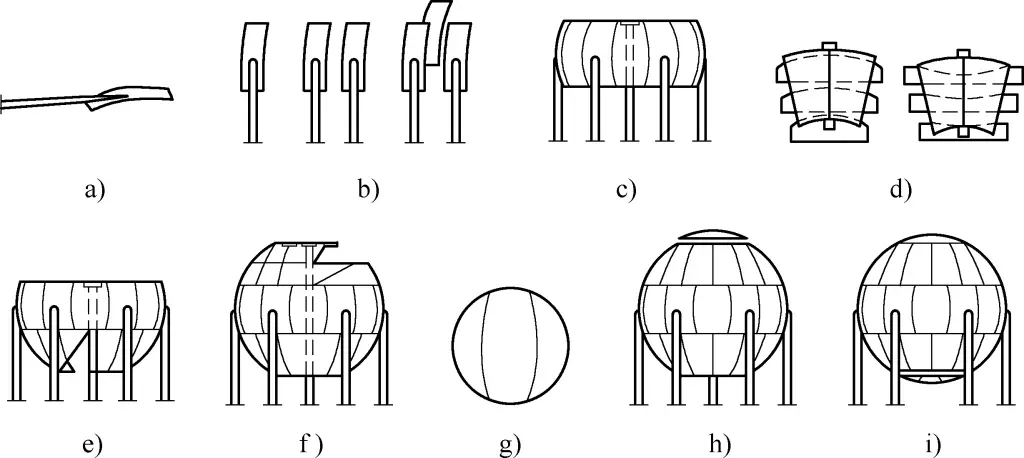
a) Column foot assembly
b) Single petal hoisting of equatorial band
c) After the single petal assembly of the equatorial band is completed, erect the central column
d) Double assembly of temperate zone petals
e) Hoisting of lower temperate zone
f) Hoisting of upper temperate zone
g) Polar cap assembly
h) Hoisting of upper polar cap
i) Hoisting of lower polar cap
Table 5 Manufacturing process regulations for sphere petals
| Serial number | Process content | Equipment |
| 1 | Layout: ① Make initial cutting plate and arc template for sphere petals; ② Make cover template (three-dimensional template); ③ Use the initial cutting template on the steel plate Mark 2-3 blanks | |
| 2 | Cutting: Make a template track according to the blank arc line for cutting | Semi-automatic cutting machine |
| 3 | Test pressing and forming: Cold pressing | 6000kN hydraulic press |
| 4 | Template trimming: ① Use a three-dimensional template to mark and correct on the formed parts; ② Make a second cutting template based on the correction amount | Suction-type cutting torch |
| 5 | Cutting: Use the formal cutting template to mark and cut according to the quantity, and correct the template track | Semi-automatic cutting machine |
| 6 | Press forming: Press according to the operating parameters during test pressing | 6000kN hydraulic press |
| 7 | Curvature inspection of sphere petals: Place on an arc-shaped jig and measure with an arc template | |
| 8 | Correction: Correct curvature deviations to meet standards | 6000kN hydraulic press |
(2) Operational techniques for sphere tank assembly
Although the size and specifications of sphere tanks vary, and different sizes and specifications of sphere tanks use different assembly methods, some operational techniques in the assembly process are the same, mainly in the following aspects.
1) Assembly welding of sphere shell plate square caps
The sphere shell plate should be welded with square caps before hoisting (the square caps for hoisting use four-side welding). Square caps are important auxiliary tools for assembling sphere tanks (see Table 6 for their structure and selection), in addition to their hoisting function, they can also be used with H-shaped clamps to fix the shell plate and adjust gaps, misalignment, and other aspects (the clamps use three-side welding for square caps).
Table 6 Selection of specifications for square caps, conical pins, and wedge irons (unit: mm)
Schematic diagram | Sphere tank specifications | Dimensions | |||||
Inner diameter | Wall thickness | a | b | c | d | ext: e | |
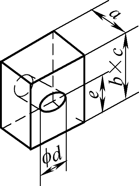 | 12450 | 37 | 30 | 50 | 50 | 30 | 25 |
| 16310 | 38.5 | 19 | 60 | 60 | 20 | 25 | |
| 12410 | 31.4 | 30 | 55 | 55 | 26 | 25 | |
| 21173 | 21 | 30 | 50 | 50 | 30 | 25 | |
| 15400 | 40 | 30 | 50 | 50 | 30 | 25 | |
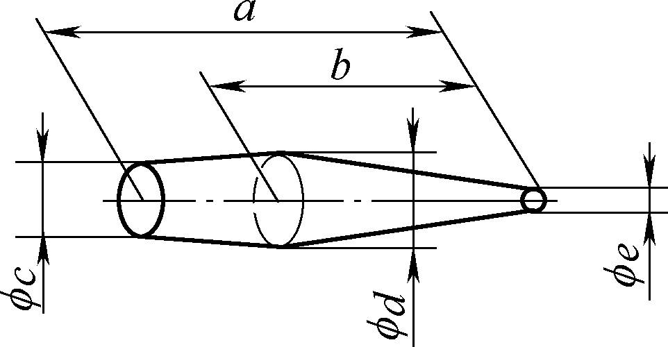 | 12450 | 37 | 230 | 190 | 30 | 35 | 8 |
| 16310 | 38.5 | 200 | 160 | 22 | 35 | 3 | |
| 12410 | 31.4 | 200 | 190 | 32 | 32 | 8 | |
| 21173 | 21 | 220 | 140 | 30 | 35 | 8 | |
| 15400 | 40 | 250 | 180 | 30 | 35 | 4 | |
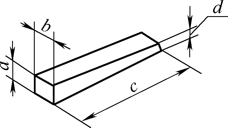 | 12450 | 37 | 38 | 38 | 200 | 8 | — |
| 16310 | 38.5 | 32 | 32 | 200 | 3 | — | |
| 12410 | 31.4 | 30 | 30 | 200 | 3 | — | |
| 21173 | 21 | 36 | 36 | 150 | 3 | — | |
| 15400 | 40 | 38 | 38 | 180 | 4 | — | |
The position of the square cap is generally welded according to the assembly needs. In principle, four are welded for vertical seams and two for circumferential seams. Figures 54a, 54b, and 54c show the arrangement of square caps for the equatorial band, temperate zone, and polar zone, respectively, with welding requirements the same as formal welding.
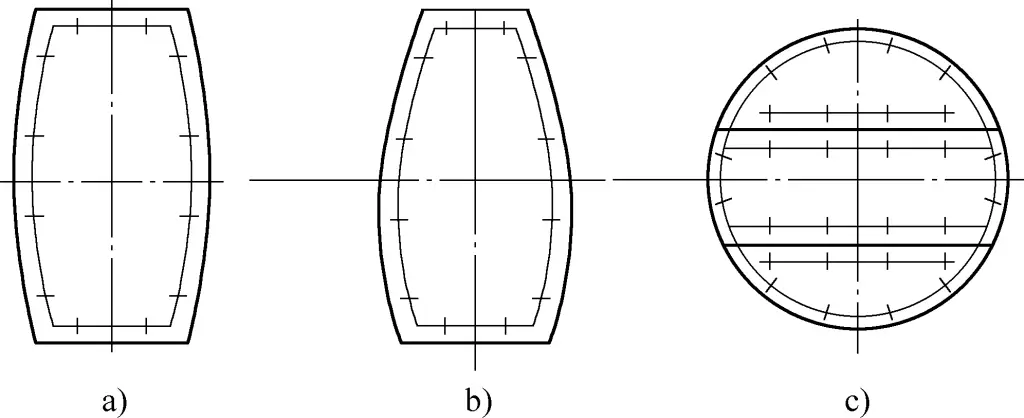
Square caps generally need to be used with conical pins, wedge irons, and H-shaped clamps to achieve shell plate adjustment. Table 6 provides the selection of specifications for square caps, conical pins, and wedge irons for different sizes of sphere tanks.
2) Clamps for sphere tank assembly
In the assembly and adjustment process of sphere tanks, in addition to the clamps shown in Table 2, the following clamps are often needed based on their characteristics.
① H-shaped clamp.
Figure 55 shows the structure of the H-shaped clamp, consisting of an H-shaped frame 1, square clamp cap 2, and conical pins 3, 4. Its main function is to adjust misalignment, edge misalignment, and gaps, and to connect adjacent plates. Generally, one set is installed every 1.3m.

1—Rectangular Frame
2—Square Cap
3, 4—Taper Pin
② Wall Bar.
As shown in Figure 56, the wall bar structure involves inserting a rigid I-beam or channel steel into a pre-welded hole plate on the shell plate, then wedging it tightly with wedge iron to adjust misalignment and offset.

③ Channel Steel Bar.
As shown in Figure 57, the channel steel bar structure involves lifting the shell plate and placing it inside the channel steel pre-positioned on the lower shell plate. After positioning, insert the taper pin through the square cap hole in the channel steel and wedge it tightly to serve as positioning and misalignment adjustment.

④ Press Horse.
As shown in Figure 58, the press horse structure is used when local misalignment or offset is difficult to adjust. A notched upright iron is welded firmly at the low end, and wedge iron is used to tighten at the high end, causing it to move downward to correct misalignment or offset.

⑤ Bolt Press Bar.
As shown in Figure 59, the bolt press bar structure involves welding a bolt at the low end, inserting the press bar into it, placing a pad at the high end, and tightening the bolt, causing the high end to move downward naturally, correcting misalignment or offset.

1—Pad
2—Bolt
3—Press Bar
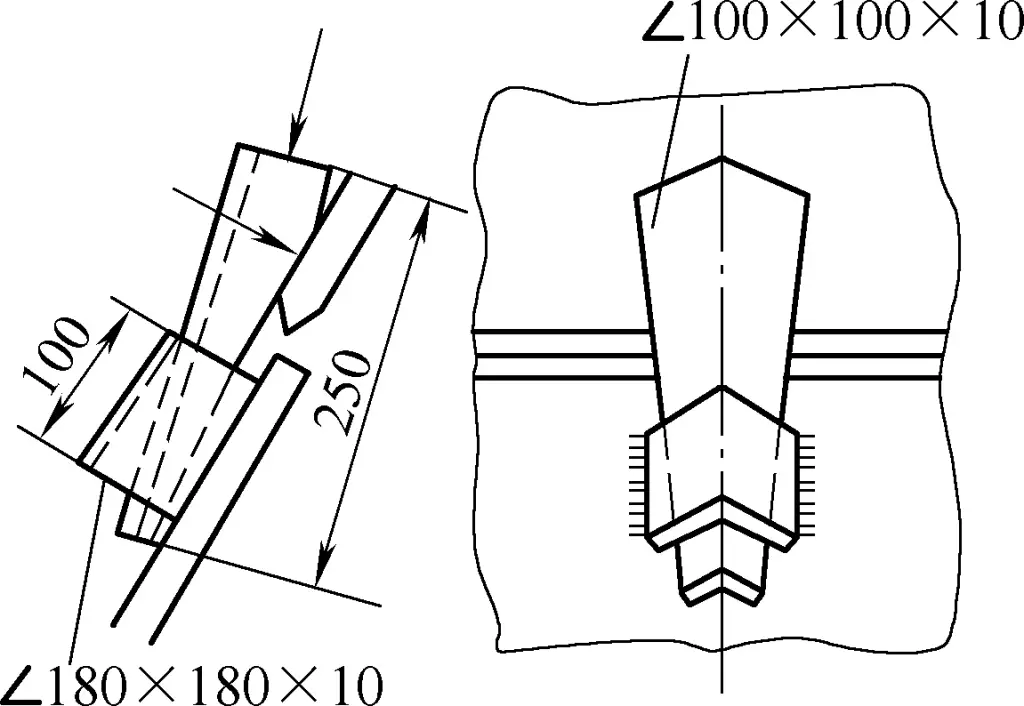
⑥ Angled Steel.
As shown in Figure 60, the angled steel structure provides good adjustment effects. When local misalignment or offset cannot be corrected using the above methods, angled steel can be used for adjustment.
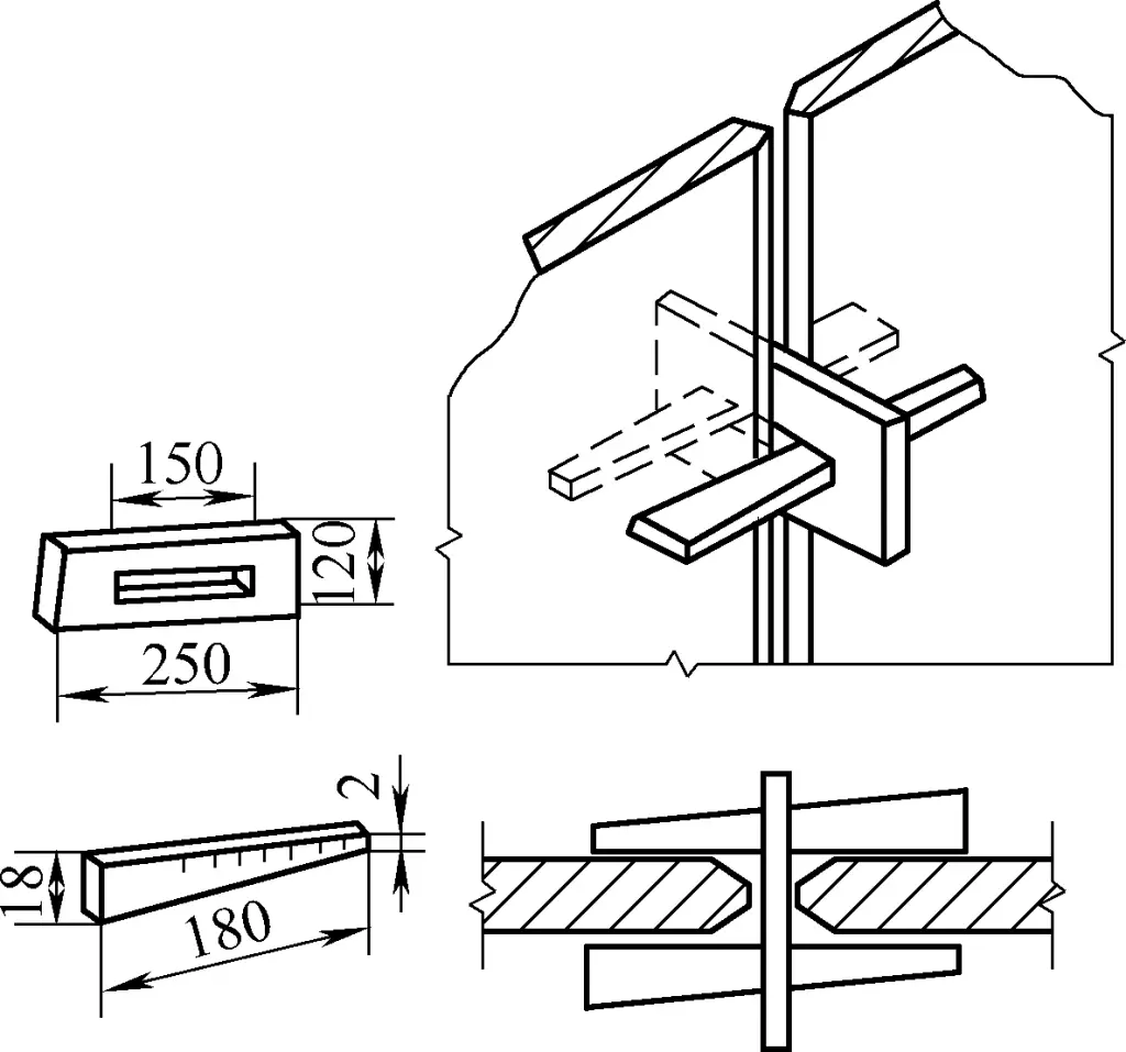
⑦ Gap Piece.
As shown in Figure 61, the gap piece structure ensures joint gap and can also adjust slight offsets.
V. Assembly Inspection
After assembly, the geometric tolerances of sheet metal components must undergo mutual and special inspections following the operator’s self-inspection. The geometric tolerance requirements vary depending on the component’s location and the industry of the product. The inspection of dimensions and geometric tolerances of sheet metal components can directly use general measuring tools and templates, special measuring tools like sample rods, or be combined with levels, plumb bobs, levels, and vertical instruments.
Additionally, for sheet metal components like boilers, pressure vessels, gas cylinders, and pressure pipelines, strength and leakage inspections are required, following the relevant national standards.
Table 7 provides the selection standards for dimensional and geometric tolerance grades for welded structures, with corresponding dimensional deviations and geometric tolerances referenced in Table 8.
Table 7 Dimensional and Geometric Tolerance Grade Selection
| Tolerance grade | Scope of application | |
| Length dimensions, angles | Geometric tolerance | |
| A | E | Welded parts with high dimensional accuracy requirements, important |
| B | F | Relatively important structures, small thermal deformation from welding and straightening, mass production |
| C | G | General structures (such as box structures) with large thermal deformation from welding and straightening |
| D | H | Structures with large allowable deviations |
Table 8 Dimensional deviation and geometric tolerance (unit: μm)
| Tolerance grade | Nominal size/mm | ||||||||||
| >30~120 | >120~400 | >400~1000 | >1000 ~2000 | >2000 ~4000 | >4000 ~8000 | >8000~12000 | >12000 ~16000 | >16000~20000 | >20000 | ||
| Dimensional deviation | A | ±1 | ±1 | ±2 | ±3 | ±4 | ±5 | ±6 | ±7 | ±8 | ±9 |
| B | ±2 | ±2 | ±3 | ±4 | ±5 | ±8 | ±10 | ±12 | ±14 | ±16 | |
| C | ±3 | ±4 | ±5 | ±8 | ±11 | ±14 | ±18 | ±21 | ±24 | ±27 | |
| D | ±4 | ±7 | ±9 | ±12 | ±16 | ±21 | ±27 | ±32 | ±36 | ±40 | |
| Geometric tolerance | E | 0.5 | 1.0 | 1.5 | 2.0 | 3.0 | 4.0 | 5.0 | 6.0 | 7.0 | 8.0 |
| F | 1.0 | 1.5 | 3.0 | 4.5 | 6.0 | 8.0 | 10 | 12 | 14 | 16 | |
| G | 1.5 | 3.0 | 5.5 | 9.0 | 11 | 16 | 20 | 25 | |||
| H | 2.5 | 5.0 | 9.0 | 14 | 18 | 26 | 32 | 36 | 40 | ||
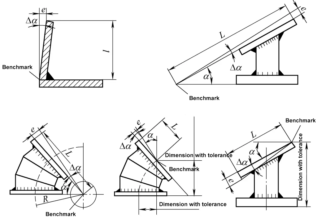
For welded structural parts, the unmarked angle limit deviation is determined according to the angle deviation in Table 9. The nominal size in the table is based on the short side as the reference side, and its length is calculated from the reference point marked on the drawing, as shown in Figure 62. If the angle is not marked on the drawing, but only the length dimension is marked, the allowable deviation should be measured in mm/m. Generally, selecting grade B does not require marking, while selecting other tolerance grades should be handled according to the technical requirements noted in Table 9 on the drawing.
Table 9 Angle deviation
| Tolerance grade | Nominal size (short side length) /mm | |||||
| ≤315 | >315~1000 | >1000 | ≤315 | >315~1000 | >1000 | |
| Angle deviation | Length deviation/mm | |||||
| A | ±20′ | ±15′ | ±10′ | ±6 | ±4.5 | ±3 |
| B | ±15′ | ±30′ | ±20′ | ±13 | ±9 | ±6 |
| C | ±1 | ±45′ | ±30′ | ±18 | ±13 | ±9 |
| D | ±1°30′ | ±1°15 | ±1° | ±26 | ±22 | ±18 |
