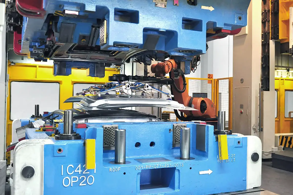
I. Overview
The stamping process is the sum of various processes in stamping processing, describing the execution rules of each process in the manufacturing process of a stamped part.
A complete stamping process should include the preparation process of stamping blanks (cutting and blanking, etc.), stamping forming processes (bending, drawing, flanging, trimming, punching, bulging, shaping, etc.) and auxiliary processes (such as lubrication, deburring, heat treatment, etc.), as well as the equipment and molds used to complete these processes and the corresponding process parameters.
Since the quality of the stamping process directly determines the rationality of stamping parts processing technology, the number and complexity of required molds, the utilization rate of raw materials, the quality and productivity of stamping parts, and other main economic and technical indicators, correctly and reasonably formulating the stamping process is a very important technical task. A good stamping process should not only ensure the production of qualified stamping parts but also require it to have the best economic and technical indicators.
Sometimes, the same stamped part may be manufactured into qualified parts by several stamping processes. In this case, it is necessary to select the best stamping process based on factors such as the complexity of the stamping process, the consumption of molds and equipment, the utilization rate of raw materials, production efficiency, the possibility of producing defective products (product quality assurance conditions), and the impact on the environment.
The main content of the stamping process design work is:
1. Analysis of stamped parts
The materials, thickness, geometric shape, size, precision requirements, and other elements of stamped parts form the stamping process characteristics of the stamped parts. They are the basic conditions for formulating the stamping process, determining the types, quantity, and sequence of stamping processes that must be used. Therefore, when formulating the stamping process, these basic elements must be carefully analyzed.
In the analysis of stamped parts, the processability of the stamped parts should be the focus of study. The processability of stamped parts includes two aspects: on one hand, it indicates whether the shape and dimensional accuracy of the stamped parts can be completed by stamping methods; on the other hand, it means whether the simplest and most convenient stamping methods can be used to manufacture them.
To make a correct analysis of the stamping process, a comprehensive consideration of various aspects is required. The manufacturing of stamping parts may involve many stamping methods, and due to the different stamping methods used, the content of their processability also varies. Even for the same part, due to different production conditions, equipment situations, mold manufacturing capabilities, and the traditions and habits of production technology at the production unit, the meaning of its stamping processability is also different.
Therefore, when analyzing the processability of stamping parts, in addition to the principles well known by general technical personnel (such as the minimum punching diameter, minimum bending radius, minimum distance between punches, etc.), it is also necessary to include the various conditions mentioned earlier into the scope of analysis and research.
In addition, the improvement of stamping production technology level and the progress of new stamping process methods may cause changes in the concept and evaluation standards of stamping parts processability, so the meaning of stamping parts processability is not unchangeable.
Based on the analysis of the processability of stamping parts, when necessary, it is possible to consider modifying the structure and size of the stamping parts themselves (under the condition of ensuring the functional use of the stamping parts) in order to simplify the stamping process and mold structure, reduce material consumption, improve the quality of stamping parts, and ultimately achieve the goal of reducing the production cost of stamping parts. Many production examples have shown that sometimes this method is very effective.
2. Selection and preparation of raw materials
The type and grade of raw materials for stamping parts are usually determined during product design based on their functional use. However, what form of raw material to use (sheet, strip, block, or coil) not only determines the preparation process in the stamping process but also affects the economic and technical level of the entire stamping process, which is an issue that cannot be ignored.
On the other hand, whether the forming process of stamping parts can be completed smoothly, and whether the dimensional accuracy of stamping parts can be guaranteed, sometimes directly depends on the stamping performance of the sheet material and the geometric shape and dimensional accuracy of the sheet material. Therefore, it is also necessary to correctly select the type and grade of raw materials based on the characteristics and requirements of stamping deformation.
3. Determination of deformation process
The determination of the deformation process is the core content of the stamping process formulation and the key to its success, which is very important. The determination of the deformation process includes determining the type and parameters of the deformation process and the sequence of the deformation process. In the work of determining the deformation process, it is necessary to follow the basic laws of stamping deformation.
4. Determination of auxiliary processes
Common auxiliary processes used in stamping production include: inter-process heat treatment, cleaning, deburring, lubrication, surface treatment, etc.
Depending on the purpose, heat treatment processes are divided into: annealing mainly to improve the plasticity of the plate and annealing mainly to reduce deformation resistance. The annealing temperature and holding time are determined by the material type, the size of the blank, and the requirements of the annealing purpose, etc.
Common methods for removing burrs include: manual deburring, barrel deburring, and grinding. The selection of these methods is determined by the shape, size, and production volume of the stamped parts.
5. Selection of mold type
The type and structure of the mold are not only determined by the stamping process it needs to complete, but also closely related to the production volume. In mass production, complex multi-process dies can be used. Although the cost of the mold is expensive, the high production efficiency can reduce the cost of the stamped parts. In small batch production, simple dies and general-purpose dies are often used.
6. Selection of stamping equipment
Based on the shape, size of the stamped parts, and the content of the stamping process to be completed, it is possible to determine the necessary tonnage, stroke, shut height, and worktable size, etc., which are the basis for selecting equipment specifications.
The selection of stamping equipment type is mainly determined by the production volume. In medium and small batch production, various types of general-purpose presses are used. In mass production, high productivity, specialized stamping equipment such as multi-station presses, high-speed presses, and stamping automation lines can be adopted.
7. Selection of mechanization and automation schemes
Mechanization and automation in the stamping production process are fundamental measures to improve labor productivity, reduce costs, and ensure safe production, which should be given full attention. In medium and small batch production, methods equipped with automatic feeding mechanisms on general-purpose presses can be used; in mass production, automated specialized presses or stamping automatic production lines composed of several automatic presses can be adopted.
8. Determine the quality inspection methods for stamping parts
The quality inspection of stamping parts is an important aspect of the design process of stamping operations. Although the quality of stamping parts is guaranteed by the performance of the raw materials, the reliability of stamping equipment and molds, and is relatively stable, it is not necessary to inspect each piece.
However, due to the high productivity of stamping equipment, if quality issues arise and timely measures are not taken, it could lead to a large amount of waste in a very short time, resulting in significant economic losses.
Therefore, when designing the stamping process, it is necessary to ensure reliable quality control measures are in place. On high-productivity automatic stamping lines, methods to ensure “on-line inspection” should be implemented even more. For the two more complex issues among the aforementioned tasks, the following analysis is made.
II. Principles for determining the stamping deformation process
The stamping deformation process is the main content of the stamping process, and its rationality directly determines the success or failure of the stamping process.
1. Now, let’s discuss the main principles that should be followed when determining the stamping deformation process.
(1) The maximum degree of deformation in the deformation zone of each deformation process cannot exceed its limit value (forming limit). Based on the geometric characteristics of the stamping parts, the types of stamping deformation processes to be used can be determined. After the shape and size of the stamping blank are determined, the total degree of deformation required to complete all forming can be determined.
Knowing the limit deformation degree (forming limit) of the stamping deformation process, the number of deformation processes required can be determined. At this point, the principle for determining the number of deformation processes is to ensure that the degree of deformation in the deformation zone of each process does not exceed its limit value.
Figure 1e shows a cylindrical stamping part made of 0.7mm thick low carbon steel plate. Based on the geometric characteristics of this stamping part, the deformation process to be used is determined to be deep drawing. By calculating under the condition of equal area, the diameter of the circular blank required is 275mm.
Based on knowing the ultimate drawing coefficient of this material and the total drawing coefficient of the part, the calculation result is that 3 drawing processes are required in total. The protrusion at the bottom of the part can be formed with one deformation process. Therefore, the stamping process for this part is determined to be: blanking, first drawing, second drawing, third drawing, trimming, and bottom forming.
Considering the large production batch, the blanking and the first drawing are combined into one process, completed with a blanking-drawing compound die. The final determined stamping process and the shape and size of the semi-finished products between each process (the result of deformation) are shown in Figure 1.
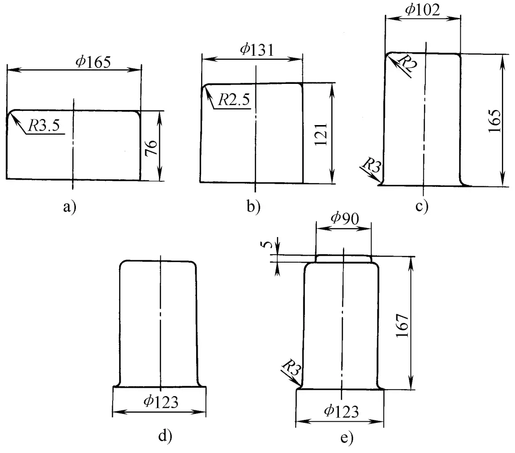
a) Blanking, first drawing
b) Second drawing
c) Third drawing
d) Trimming
e) Bottom forming
(2) The process parameters and deformation conditions of each forming process should comply with the laws of stamping deformation tendency, making the parts of the blank that should deform (deformation zone) relatively “weak areas” to ensure that the deformation zone of the blank deforms in a predetermined manner during that forming process.
Blanks of different shapes and sizes, in different forming processes, have different force conditions and possible deformation modes in their parts, and the content and conditions of their deformation tendency laws are also different.
The part with a circular hole flanging shown in Figure 2, although simple in shape, may have different deformation tendencies due to the different dimensional relationships between its parts, necessitating the use of completely different stamping processes (stamping forming operations) to manufacture qualified parts.
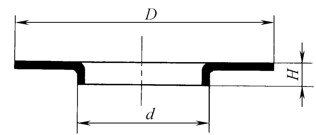
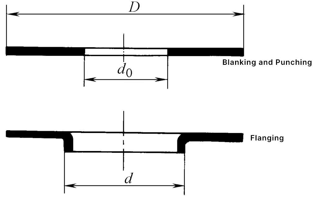
If the outer diameter D of the part in Figure 2 is relatively large, while the height H of the flange after flanging is relatively small, based on the dimensional relationship between the various parts of the blank before deformation (the relationship between the blank’s outer diameter D and the inner hole d), by utilizing the law of stamping deformation tendency, it can be concluded that “the stamping process of directly forming from a ring-shaped blank by flanging can be used.”
Therefore, the stamping process to be used can be determined as: blanking, punching, flanging (see Figure 3). If the production volume is large, blanking and punching can be combined into one operation, using a set of blanking-punching compound dies. If the tooling and equipment conditions allow, blanking, punching, and flanging can also be combined into one operation, using a set of blanking-punching-flanging compound dies.
If the outer diameter size D of this part is relatively small, and the height H of the flange after flanging is relatively large, according to the law of stamping deformation tendency, the deformation that occurs may not be the flanging deformation inside the blank, but the drawing deformation of the blank’s outer edge shrinking. Therefore, the stamping process shown in Figure 3 will not be able to ensure the processing of qualified parts.
In this case, according to the principle of the law of stamping deformation tendency, the size of the blank’s outer diameter should be appropriately increased to prevent the outer diameter of the blank from shrinking during the flanging process. Finally, after the flanging is completed, an additional trimming operation is added to achieve the required outer diameter size. Thus, the reasonable stamping process is: blanking, punching, flanging, trimming (see Figure 4).
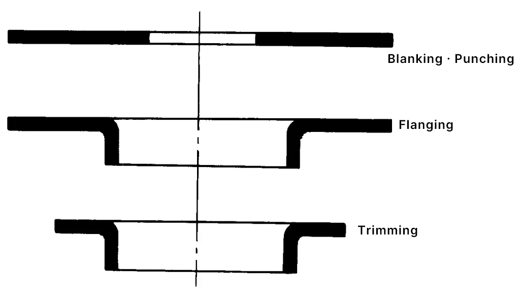
For such parts, another stamping process can also be used, which is to first perform punching and flanging operations under the condition of appropriately widening the strip material, and then use the blanking operation to separate the blank from the strip material. This process can eliminate one trimming operation. Although both stamping processes can process qualified parts, there are many differences in the structure of the molds used, positioning, and operation methods.
In production conditions, a comparative analysis should be made to correctly select. Of course, a compound die can also be used to combine punching, flanging, and blanking into one operation.
In this case (when applying a compound die), it is necessary to appropriately determine the heights of the blanking punch, blanking die, punching punch, punching die, and flanging punch to ensure that each process (blanking, punching, flanging, etc.) proceeds in the correct order as established, in accordance with the laws of stamping deformation tendency.
When the flange height H of the round hole flanged part is large, if the stamping process shown in Figure 3 or Figure 4 is still used, it is necessary to reduce the diameter of the punching before flanging to achieve the required flange height H. As a result, the flanging coefficient will be less than the limit value allowed by the plate material’s stamping performance, thus such a stamping process cannot be used to process qualified parts.
In this case, a more complex stamping process must be adopted, namely four processes: blanking, drawing, punching the bottom hole, and flanging (see Figure 5).
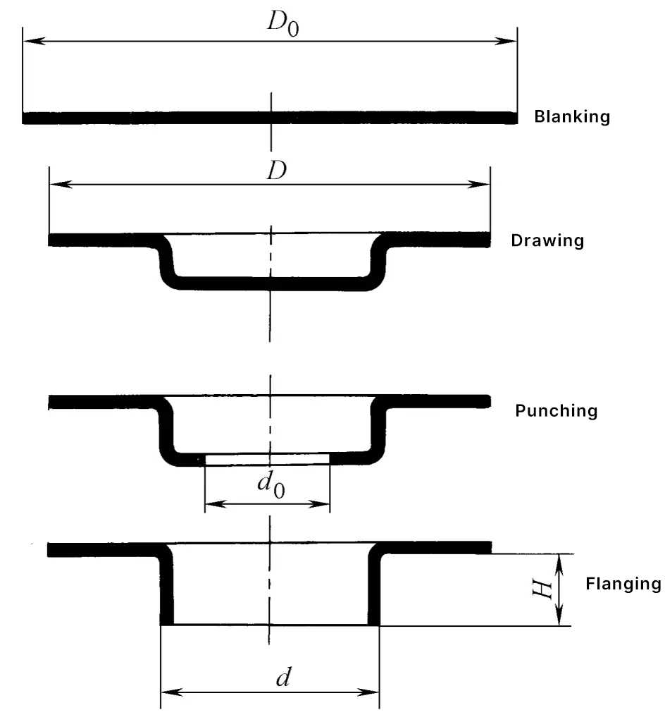
When the outer diameter size accuracy of the stamped parts is required, in order to remove the defects of the flange edge’s outer circumference being not round due to the anisotropy of the plate material after drawing, a trimming process should also be added after the drawing process. Of course, when the production volume is large, the consolidation of processes and the application of compound dies should also be considered.
In the analysis work of the stamping process of the stamped parts shown in Figures 2 to 4, the minimum limit size relationship listed in Table 1, where the outer diameter of the blank does not change during flanging, can be used as a basis. The values in the table are the results of actual stamping experiments, and they are applicable to low carbon steel plates and conditions using spherical end face punches. The symbols D, d, and d0 in the table are the dimensions of the blank before stamping (see Figure 3).
Table 1 The limit of d / d0 when flanging with a spherical end face punch without changing the outer diameter of the blank
| Friction factor | d0/D | |||
| 0.5 | 0.6 | 0.7 | 0.8 | |
| 0.15 | 1.35 | 1.2 | 1.15 | 1.08 |
| 0.25 | 1.48 | 1.3 | 1.2 | 1.12 |
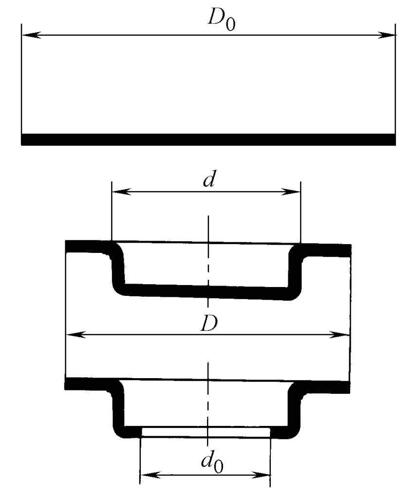
In the design of the stamping process for deep-drawn parts, it is also necessary to follow the principle of the tendency of stamping deformation. The geometric shapes of the two cylindrical deep-drawn parts in Figures 6 and 7 are the same, both are deep-drawn parts with a round hole at the bottom. However, due to the different diameters of the bottom hole, different stamping processes must be used for processing.
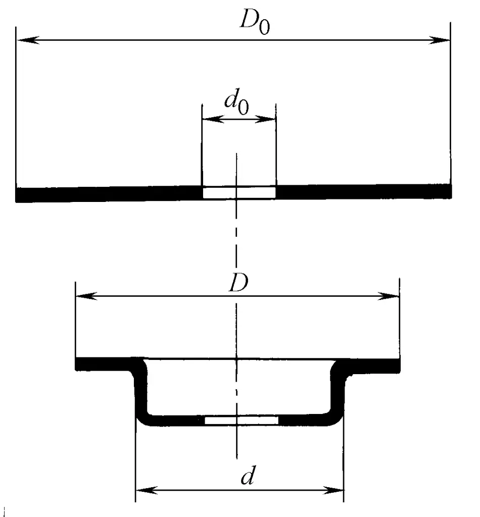
If the diameter of the hole at the bottom of the deep-drawn part is small, the diameter of the bottom hole will not expand when deep drawing with a ring blank with holes. Therefore, the stamping process shown in Figure 6 can be adopted, that is, blanking, punching, and deep drawing. Here, blanking and punching can also be combined into one process, and then deep drawing with a ring blank. When the production batch is large, it can also be considered to combine blanking, punching, and deep drawing into one process, completed with a set of compound dies.
If the diameter of the hole at the bottom of the deep-drawn part is large, according to the law of stamping deformation tendency, the annular part with an outer diameter of d and an inner diameter of d 0 may become a relative “weak area”. Therefore, during the deep drawing process, the size of the bottom hole may expand, or even undesired hole expansion and flanging deformation may occur, making it impossible to carry out the stamping process that forms the part through deep drawing deformation.
In this case, the stamping process shown in Figure 7 must be adopted, arranging the bottom punching process after the deep drawing process. Of course, at this time, blanking, deep drawing, and bottom hole punching three processes can also be combined into one process, completed with a set of compound dies.
It should be noted that when determining the height of the punching punch in the design work of the compound die, it is necessary to ensure the sequence determined by the law of stamping deformation tendency, that is, the sequence of blanking, deep drawing, and bottom hole punching.
The above analysis is based on axially symmetrical cylindrical deep-drawn parts and circular hole flanging parts as examples, and its basic principles are also applicable to non-axially symmetrical stamping parts.
(3) When determining the deformation process, a comprehensive analysis must be carried out together with the structure of the mold, the working principle, and other issues.
In stamping processing, all stamping deformations are completed by the corresponding mold structure and working principle. Therefore, a certain deformation process necessarily requires the mold to have corresponding functions and structures.
Due to the existence of this relationship, when determining the deformation process and the combination of various deformation processes, it is necessary to consider what kind of mold can complete the determined deformation process. On the one hand, the possibility of using the mold to complete the stamping deformation process must be considered, and on the other hand, the complexity of the corresponding mold structure and the economic issues such as mold cost consumption must also be analyzed.
The bent part with multiple right angles shown in Figure 8 can be processed using various stamping processes. A more commonly used stamping process is to use two bending processes. The first bending process bends the two right angles on the outside of the part, and then another set of molds is used to bend the two right angles on the inside. This bent part can also be bent into four right angles in one bending process.
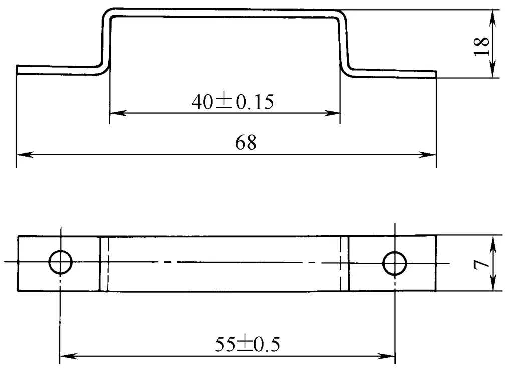
The most intuitive stamping process involves using the mold shown in Figure 9 to bend four right angles in a single stamping operation. Although the mold used in this process is very simple in structure, and the working principle of the mold is feasible according to a simple idea.
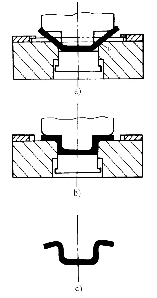
However, during the operation of this type of mold, the rotation of the two side arms of the blank is obstructed by the punch. As a result, not only is the bending deformation of the two inner right angles hindered, but also harmful bending occurs in parts that should not be bent, damaging the dimensional accuracy of the stamped parts (see Figure 9).
In this case, to ensure the correct shape and dimensional accuracy of the bent parts, while also being able to use an efficient multi-angle single bending stamping process, the type of mold shown in Figure 10 can be used. When the dimensions of the side arms of the bent parts are appropriate, the simpler mold structure shown in Figure 11 can also be used to complete all angle bending work in a single stroke of the press.
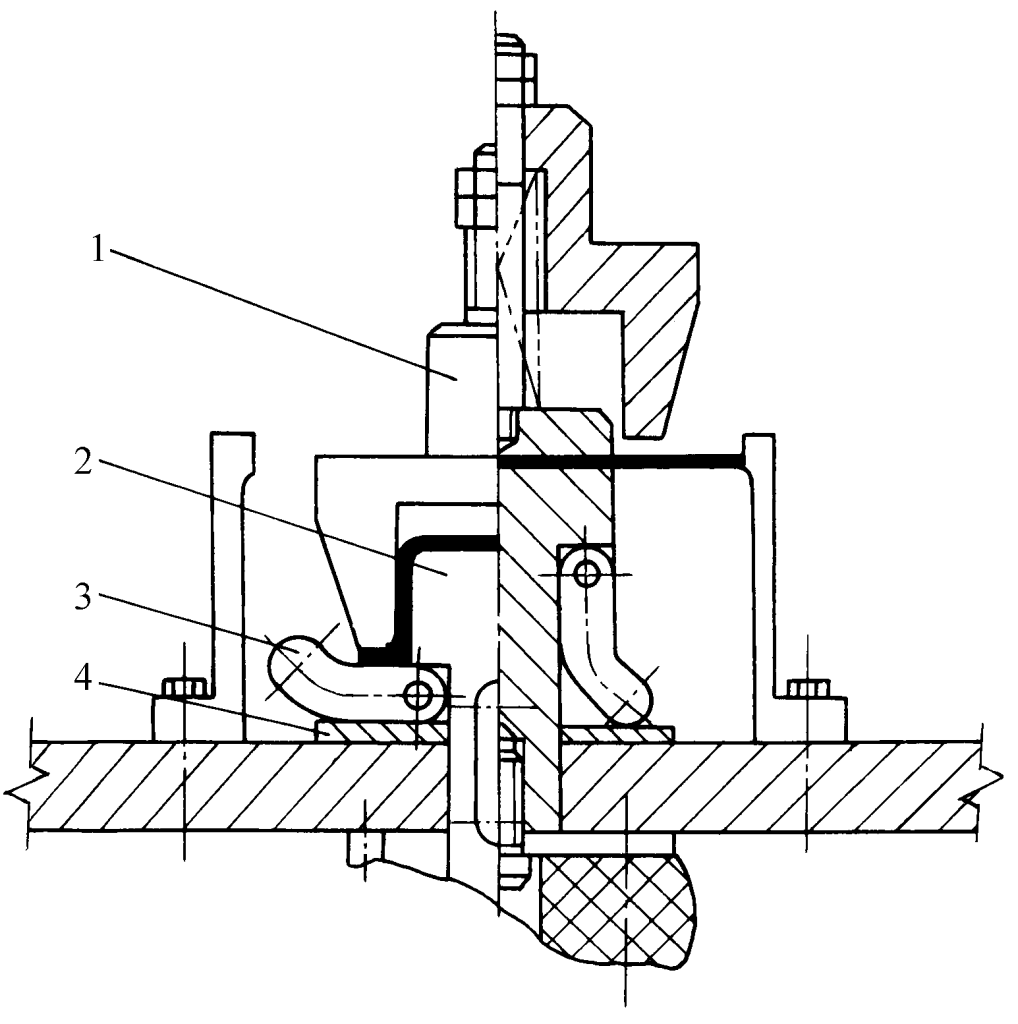
1—Die
2—Punch
3—Swing block
4—Backing plate
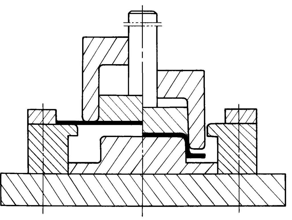
In fact, the working principle of this set of molds is equivalent to the stamping process of two bending operations. It first bends the two right angles on the outer side of the blank, and then bends the two right angles on the inner side of the blank. The sequence of bending is achieved by the height difference between the bending punch and the four bending dies.
2. When determining the sequence of forming processes, the following principles should be followed.
In the work of developing stamping processes for parts with complex shapes, multiple forming processes are often needed to complete the stamping. At this time, arranging the sequence of each forming process is a complex and important issue, and even the key to the success of the stamping process.
(1) Multi-process stamping forming is essentially the process of gradually changing the shape of a flat-shaped sheet metal blank, in a certain order, to approach and finally become the shape of the stamped part. Therefore, each forming process should complete a certain processing task in this process, play a part, and change the shape of a certain part or the overall blank, towards the direction close to the shape of the stamped part.
To achieve this, when arranging the sequence of forming processes, it must be ensured that in each forming process, the part that needs to be shaped is definitely in a relatively “weak area” under the force conditions of that process, and the result of this process does not hinder the subsequent forming processes, that is, the formation of relatively “weak area” conditions in subsequent forming processes.
(2) In the stamping process with multiple forming processes, after a certain forming process, if a part of the shape of the stamped part has already been formed, then in all subsequent forming processes, this already formed part should not undergo any other deformation.
(3) In the semi-finished product formed after the forming process, it can be divided into formed parts (the shape and size are completely the same as a part of the finished stamped part) and parts to be formed in the subsequent deformation process.
The parts to be formed on the semi-finished product, separated by the already formed parts, can only be processed within their own respective ranges. The parts to be formed, separated by the already formed parts, no longer have deformational connections and influences between them, so the deformation processes within their own ranges can be independently arranged, and there will be no material transfer between them.
(4) In the calculation work of designing the stamping process, it should be ensured that the quantity (weight or area) of the sheet metal in the area to be deformed, separated by the already deformed area, is sufficient for the needs of the corresponding part of the stamped part to be formed later. It should not be less than the required amount, but also should not be more than needed.
(5) On stamping blanks and semi-finished products of processes, for parts that should undergo plastic deformation in subsequent processes, operations such as punching and notching should not be arranged before the deformation process. In addition, all punching, notching, and trimming may change the tendency of stamping deformation, so the arrangement of these processes should meet the requirements of the stamping process for deformation tendency and its conditions.
The two examples shown in Figures 12 and 13 are stamping processes that require multiple operations. By analyzing the stamping process of these two parts, the significant importance of the above principles in practical application can be clearly demonstrated.
The example shown in Figure 12 involves a stamping process with six operations. The first and second deep drawing operations are calculated based on the maximum deep drawing coefficient. In these two deep drawing operations, the bottom of the semi-finished product after deep drawing is formed into a spherical shape, with the aim of reserving enough material at the bottom for the third forming operation.
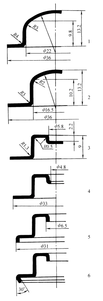
1—Blanking, deep drawing
2—Deep drawing
3—Forming
4—Punching, trimming
5—Flanging of outer edge, flanging of inner hole
6—Disassembling of outer edge
The cylindrical part with a diameter of 16.5mm formed after the second deep drawing process is the formed area, which divides the semi-finished product into two parts to be formed, inside and outside. Starting from the third forming process until the final sixth process, all forming is carried out within the respective ranges of the two areas to be deformed, between which there is no longer any deformation relationship, allowing the sequence of their respective forming processes to be arranged independently.
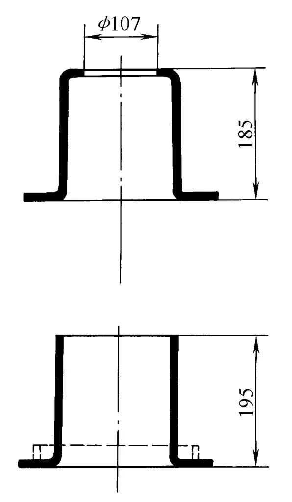
Figure 13 shows the stamping process requiring 9 steps. The first to fifth processes are determined according to the calculation method for cylindrical deep-drawn parts. The cylindrical part with a diameter of 120mm formed in the fifth deep drawing process is the formed area, which divides the semi-finished product into two parts to be formed, inside and outside, so the subsequent deformation processes are carried out within their respective ranges.

1—Blanking
2, 3, 4, 5—Deep drawing
6—Sizing R1.5
7—Trimming the edge
8—Flanging the edge
9—Cutting the bottom
From the perspective of deformation and force, there is no longer any mutual influence between them, so the sequence of subsequent deformation processes is determined according to the deformation tendency of each part itself, no longer constrained by other parts. The die used in the ninth bottom cutting process is relatively complex, and when the batch size is not large, the bottom can be cut on a lathe, or it can be completed by the punching-flanging method shown in Figure 14.
III. Selection of Stamping Equipment
The stamping forming process is completed on stamping equipment, so the reasonable selection of stamping equipment not only determines whether the stamping process can proceed smoothly, but also directly affects the economic effect of the stamping process.
When formulating the stamping process, it is necessary to select the stamping equipment based on the required deformation force and working stroke, mold installation space, and other conditions after determining the forming process. Sometimes, another situation may arise: determining a reasonable stamping process based on the existing stamping equipment.
Currently, the most used in stamping production are mechanical presses and hydraulic presses. For stamping production, these two types of equipment have their advantages and disadvantages, and the comparison of their characteristics can be seen in Table 2.
Table 2 Comparison of Mechanical Presses and Hydraulic Presses
| Comparison Content | Mechanical Press | Hydraulic Press |
| Stroke Adjustment | Usually not adjustable | Easy |
| Bottom dead center position | Fixed | Not fixed |
| Adjustment of slider force | Impossible | Possible |
| Adjustment of slider speed | Impossible | Adjustable |
| Overload damage | Possible | Impossible, absolutely safe |
| Give the slider position of the nominal tonnage force | Approaching the bottom dead center | Full stroke |
| Productivity | Height | Lower |
| Maintenance | Simple | Relatively complex |
| Work environment | Tidy | Prone to oil stains |
Mechanical presses and hydraulic presses have significant differences in performance, so after the equipment selection, it is necessary to design the die according to the characteristics of the stamping equipment.
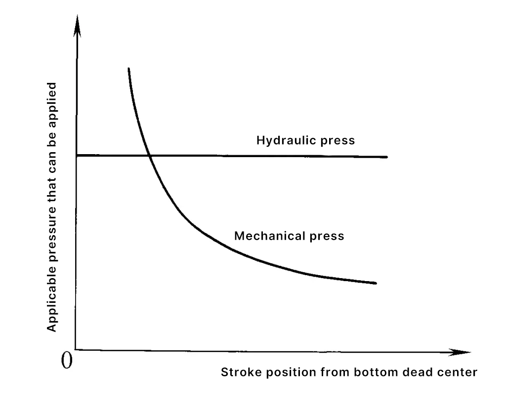
The hydraulic press can provide its nominal tonnage (force) throughout the entire stroke range to complete the deformation process. The force that a mechanical press can provide, limited by the strength of its own transmission system, may vary with the crankshaft’s rotational position and is only likely to provide the nominal tonnage force near the bottom dead center of the slide.
The comparison of the force and stroke relationship curves that mechanical presses and hydraulic presses can provide is shown in Figure 15.
After determining the type of stamping equipment, based on the characteristics of the deformation process, the total required process force (when the force application time overlaps), the shape and size of the stamped parts and blanks, the parameters of the mold, and operational requirements, etc., it is possible to determine the required slide force, stroke, shut height, the structure and size of the worktable and bed, stroke number, and other equipment parameters, and on this basis, select the specifications and model of the suitable equipment.
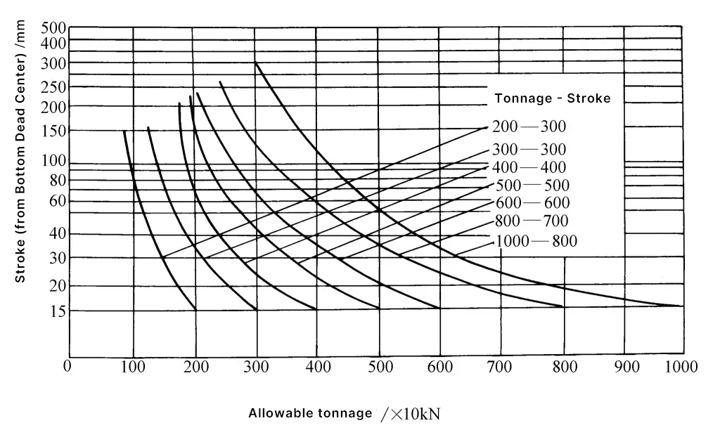
When selecting a mechanical press by tonnage (force), it should be ensured that the allowable slide force of the press at any moment throughout the entire stroke range is greater than the total deformation force required at the corresponding moment. That is to say, the resultant force curve obtained by adding the curves of the forces required for various deformation processes to be completed in one stroke should be lower than the curve of the allowable slide force throughout the entire stroke range.
The relationship curve between the allowable slide force and stroke of the crank press is essential information required when selecting equipment, which the equipment manufacturer must provide to the user unit as the basis for formulating the process. If there is a lack of practical information, the relationship curve between the allowable slide force and stroke of common crank presses given in Figure 16 can also be referred to.
Specifications and various parameters of commonly used mechanical presses and hydraulic presses are shown in Tables 3 to 5.
Table 3 Basic parameters of closed single-point presses
| Nominal pressure/kN | Nominal pressure stroke/mm | Slide stroke/mm | Slide stroke frequency/(times/min) | Maximum shut height/mm | Enclosure height adjustment/mm | Distance between guide rails/mm | Front and rear dimensions of the slider bottom/mm | Worktable size/mm | |||
| Type I | Type II | Type I | Type II | Left and right | Front and back | ||||||
| 1600 | 13 | 250 | 200 | 20 | 32 | 450 | 200 | 880 | 700 | 800 | 800 |
| 2000 | 13 | 250 | 200 | 20 | 32 | 450 | 200 | 980 | 800 | 900 | 900 |
| 2500 | 13 | 315 | 250 | 20 | 28 | 500 | 250 | 1080 | 900 | 1000 | 1000 |
| 3150 | 13 | 400 | 250 | 16 | 28 | 500 | 250 | 1200 | 1020 | 1120 | 1120 |
| 4000 | 13 | 400 | 315 | 16 | 25 | 550 | 250 | 1330 | 1150 | 1250 | 1250 |
| 5000 | 13 | 400 | — | 12 | — | 550 | 250 | 1480 | 1300 | 1400 | 1400 |
| 6300 | 13 | 500 | — | 12 | — | 700 | 315 | 1580 | 1400 | 1500 | 1500 |
| 8000 | 13 | 500 | — | 10 | — | 700 | 315 | 1680 | 1500 | 1600 | 1600 |
| 10000 | 13 | 500 | — | 10 | — | 850 | 400 | 1680 | 1500 | 1600 | 1600 |
| 12500 | 13 | 500 | — | 8 | — | 850 | 400 | 1880 | 1700 | 1800 | 1800 |
| 16000 | 13 | 500 | — | 8 | — | 950 | 400 | 1880 | 1700 | 1800 | 1800 |
| 20000 | 13 | 500 | — | 8 | — | 950 | 400 | 1880 | 1700 | 1800 | 1800 |
Table 4 Basic Parameters of Open Type Press
| Name | Measurement | |||||||
| Nominal Pressure/kN | 40 | 63 | 100 | 160 | 250 | 400 | 630 | |
| Distance from the Bottom Dead Point of the Slider at Nominal Pressure/mm | 3 | 3.5 | 4 | 5 | 6 | 7 | 8 | |
| Slider Stroke/mm | 40 | 50 | 60 | 70 | 80 | 100 | 120 | |
| Standard Stroke Rate/(times/min) | 200 | 160 | 135 | 115 | 100 | 80 | 70 | |
| Maximum Shut Height/mm | 160 | 170 | 180 | 220 | 250 | 300 | 360 | |
| Shut Height Adjustment/mm | 35 | 40 | 50 | 60 | 70 | 80 | 90 | |
| Worktable Size/mm | Left and Right | 280 | 315 | 360 | 450 | 560 | 630 | 710 |
| Front and Back | 180 | 200 | 240 | 300 | 360 | 420 | 480 | |
| Workbench hole size/mm | Left and right | 130 | 150 | 180 | 220 | 260 | 300 | 340 |
| Front and back | 60 | 70 | 90 | 110 | 130 | 150 | 180 | |
| Diameter | 100 | 110 | 130 | 160 | 180 | 200 | 230 | |
| Distance between columns (not less than)/mm | 130 | 150 | 180 | 220 | 260 | 300 | 340 | |
| Pattern hole size (diameter × depth)/mm | Φ30×50 | Φ50×70 | ||||||
| Workbench plate thickness/mm | 35 | 40 | 50 | 60 | 70 | 80 | 90 | |
| Tilt angle (not less than)/(°) | 30 | 30 | 30 | 30 | 30 | 30 | 30 | |
| Name | Measurement | ||||||||
| Nominal pressure/kN | 800 | 1000 | 1250 | 1600 | 2000 | 2500 | 3150 | 4000 | |
| Distance from the bottom extreme point of the slider when nominal pressure occurs/mm | 9 | 10 | 10 | 12 | 12 | 13 | 13 | 15 | |
| Slider stroke/mm | 130 | 140 | 140 | 160 | 160 | 200 | 200 | 250 | |
| Standard strokes per minute (/min) | 60 | 60 | 50 | 40 | 40 | 30 | 30 | 25 | |
| Maximum closed height/mm | 380 | 400 | 430 | 450 | 450 | 500 | 500 | 550 | |
| Closed height adjustment/mm | 100 | 110 | 120 | 130 | 130 | 150 | 150 | 170 | |
| Worktable size/mm | Left and right | 800 | 900 | 970 | 1120 | 1120 | 1250 | 1250 | 1400 |
| Front and back | 540 | 600 | 650 | 710 | 710 | 800 | 800 | 9000 | |
| Worktable hole size/mm | Left and right | 380 | 420 | 460 | 530 | 530 | 650 | 650 | 700 |
| Front and back | 210 | 230 | 250 | 300 | 300 | 350 | 350 | 400 | |
| Diameter | 260 | 300 | 340 | 400 | 400 | 460 | 460 | 530 | |
| Distance between columns (not less than)/mm | 380 | 420 | 460 | 530 | 530 | 650 | 650 | 700 | |
| Pattern hole size (diameter × depth)/mm | Φ60×75 | Φ70×80 | T-slot | ||||||
| Worktable thickness/mm | 100 | 110 | 120 | 130 | 130 | 150 | 150 | 170 | |
| Tilt angle (not less than)/(°) | 30 | 25 | 25 | 25 | |||||
Table 5 Four-column universal hydraulic press
| Main technical specifications | Nominal pressure/kN | Slider stroke/mm | Ejection force/kN | Worktable size/mm (front to back × left to right × height from ground) | Working speed/(mm/s) | Maximum distance from moving beam to worktable/mm | Liquid working pressure/MPa | |
| Model | Y32-50 | 500 | 400 | 75 | 490×520×800 | 16 | 600 | 20 |
| YB32-63 | 630 | 400 | 95 | 490×520×800 | 6 | 600 | 25 | |
| Y32-100A | 1000 | 600 | 165 | 600×600×700 | 20 | 850 | 21 | |
| Y32-200 | 2000 | 700 | 300 | 760×710×900 | 6 | 1100 | 20 | |
| Y32-300 | 3000 | 800 | 300 | 1140×1210×700 | 4.3 | 1240 | 20 | |
| YA32-315 | 3150 | 800 | 630 | 1160×1260 | 8 | 1250 | 25 | |
| Y32-500 | 5000 | 900 | 1000 | 1400×1400 | 10 | 1500 | 25 | |
| Y32-2000 | 20000 | 1200 | 1000 | 2400×2000 | 5 | 800~2000 | 26 | |

