During the process of creating the sheet metal component development drawing, it is also necessary to consider the impact of the thickness of the processing material, that is, to make appropriate plate thickness adjustments.
Generally speaking, for sheet materials with a thickness of less than 3mm, no plate thickness adjustment is required. It can be calculated according to the central diameter of the sheet material or according to the inner and outer surface cutting lines. The dimensions after forming are within the allowable deviation range. When the plate thickness is greater than 3mm, it should be calculated according to the central diameter of the sheet material. For convenience of description, the calculations for the following developed materials refer to the central diameter of the sheet material.
1. Development Calculation of Cylindrical Shells
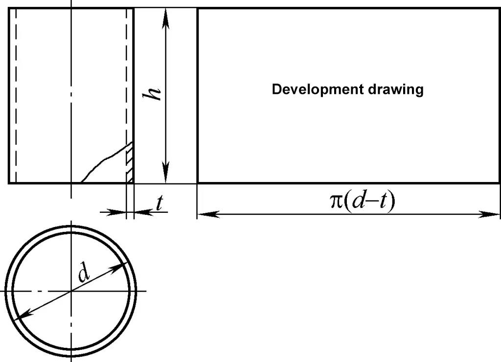
The cylindrical shell belongs to the cylindrical surface, and its development drawing is a rectangle. One side of the rectangle is equal to the circumference of the cylinder π(d-t), and the other side is the height h of the cylinder, as shown in Figure 1. In the figure, d is the outer diameter of the cylinder and t is the plate thickness.
2. Development Calculation of Right Circular Cones
The development drawing of the right circular cone is a sector arc. The calculation formula for the development drawing of the right circular cone shown in Figure 2 is:
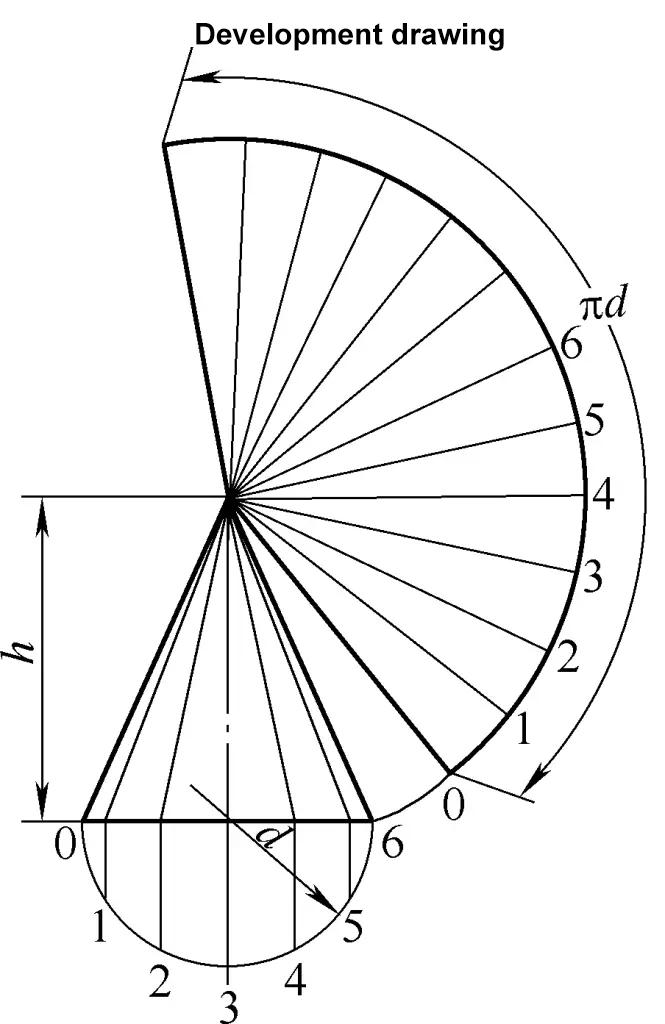
R=1/2√(d2+4h2)
α=180d/R
L=2Rsinα/2
In the formula
- R – Radius of the sector arc (mm);
- α – Sector angle (°);
- L – Chord length of the sector arc (mm).
3. Development Calculation of Truncated Right Circular Cones
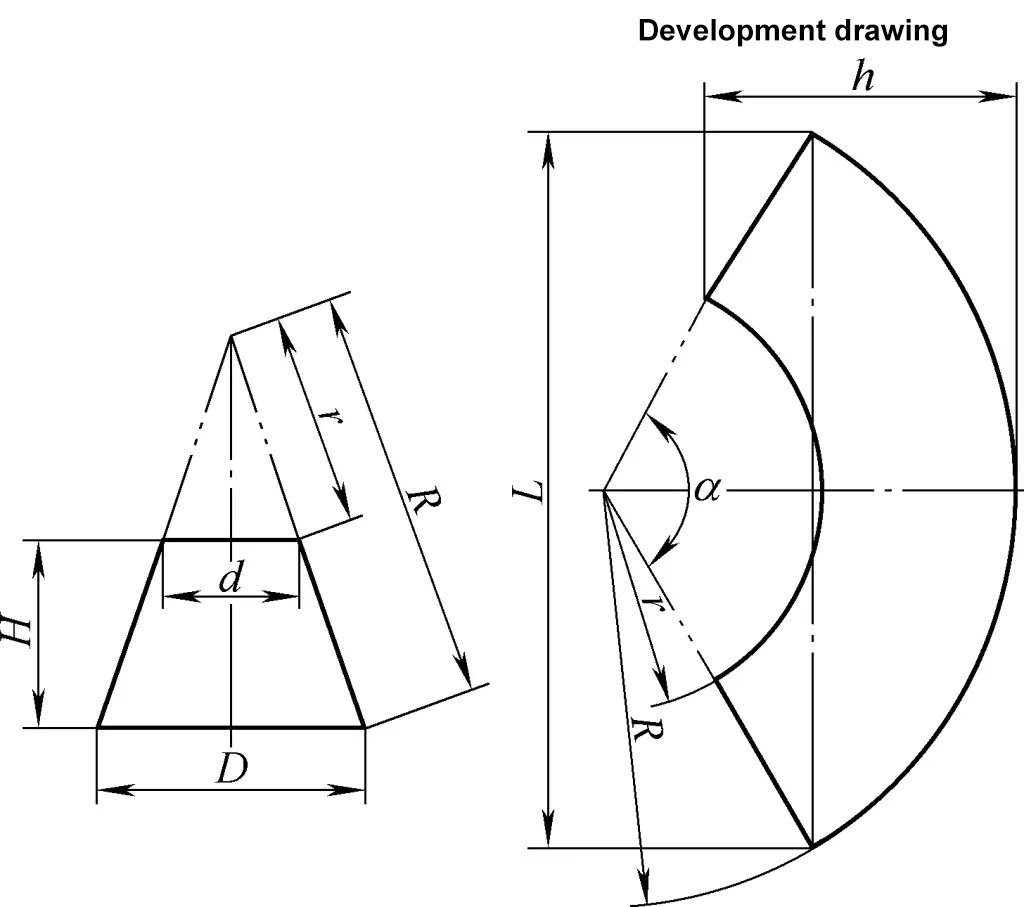
The development drawing of the truncated right circular cone is a concentric sector arc. The calculation formula for the development drawing of the truncated right circular cone shown in Figure 3 is:
R=√{(D/2)2+[DH/(D-d)]2}
r=dR/D
α=180d/r
L=2Rsinα/2
h=R-rcosα/2
When α>180°, h=R+rsin[(α-180)/2]
For the meanings of the symbols in the formula, refer to Figure 3.
4. Development Calculation of Oblique Right Circular Cones
The development drawing of the oblique right circular cone is an irregular sector arc. The calculation formula for the development drawing of the oblique right circular cone shown in Figure 4 is:
tanβ1=h/[1/2(D1-d1)+l]
tanβ2=h/[1/2(d1-D1)+l]
D=D1-t/2 (sinβ1+ sinβ2)
d=d1-t/2 (sinβ1+ sinβ2)
A=Dl/(D-d)
H=Ah/l
fn=√[(A-D/2cosαn)2+(D/2)2sin2αn+H2]
yn=fn(1-h/H)
m=Dsin(180°/n )
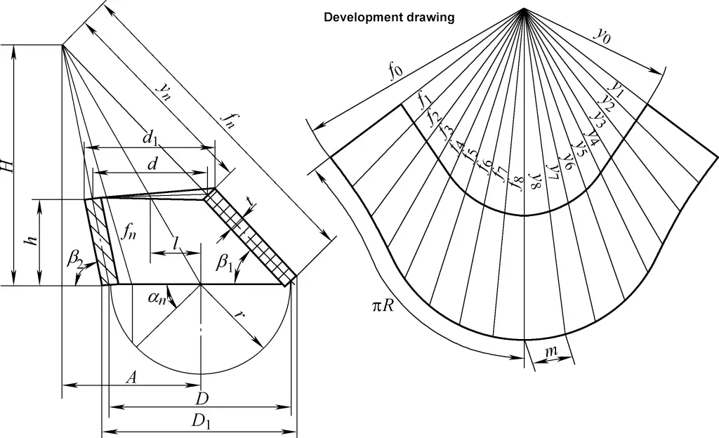
In the formula
- D1, d1 – Outer diameters of the large and small ends (mm);
- D, d – Central diameters of the large and small ends (mm);
- h – Central height (mm);
- l – Eccentric distance (mm);
- n – Number of divisions around the circumference; the higher the number of divisions, the more complex the calculation but the more accurate the drawing. Generally, the number of divisions can be referenced in Table 1;
- fn, yn – Lengths of the slant lines of the oblique right circular cone (mm).
Table 1 Number of Divisions for Sheet Metal Developments
| Radius of Developed Piece/mm | Number of Divisions |
| Within 50 | 8 |
| 50~150 | 12 |
| 150~250 | 16 |
| 250~400 | 24 |
| 400~650 | 32 |
| 650~1000 | 48 |
| 1000~2000 | 64 |
| Over 2000 | 96 |
5. Development Calculation of the Orthoconic Rectangular to Round Transition Duct
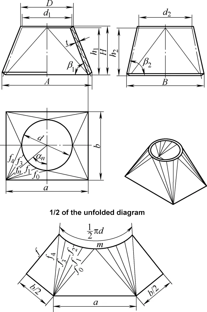
The orthoconic rectangular to round transition duct shown in Figure 5 consists of four equal oblique right circular conical surfaces and four symmetric triangular planes. The calculation formula for its development drawing is:
tanβ1=2H/(A-D)
tanβ2=2H/(B-D)
d1=D-tsinβ1
d2=D-tsinβ2
d=1/2(d1+d2)=D-t/2(sinβ1+sinβ2)
a=A-2tsinβ1
b=B-2tsinβ2
h1=H-t/2cosβ1
h2=H-t/2cosβ2
h=1/2(h1+h2)=H-t/4(cosβ1+cosβ2)
f0=1/2√[a2+(b-d2)2+4h22]
fn=1/2√(a-dsinαn)2+(b-dcosαn)2+4h2(when 0<α<90°)
fn=1/2√(a-dsinαn)2+(b-dcosαn)2+4h12(when α=90°)
f=1/2√[(a-d)2+4h12]
m=πd/n
For the meanings of the symbols in the formula, refer to Figure 5, and n is the number of divisions around the circumference. Generally, the number of divisions in Table 1 can meet calculation requirements.
