Standard Sheet Metal Gauges Chart
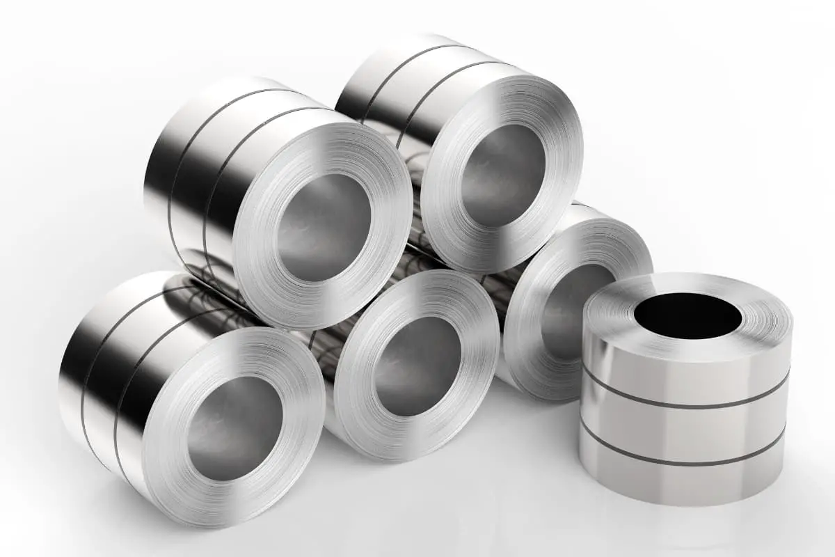
Did you know that the thickness of sheet metal is measured in gauges, where a higher gauge means thinner metal?…
This article dives into the fascinating world of sheet metal unfolding, explaining the essential techniques and methods used to create accurate flat patterns from 3D designs. Discover the traditional and software-assisted methods that engineers rely on, ensuring precision and efficiency in manufacturing. From basic principles to advanced CAD techniques, you’ll gain valuable insights into the art and science behind sheet metal fabrication. Explore how mastering these skills can optimize production and reduce costs in various industries.

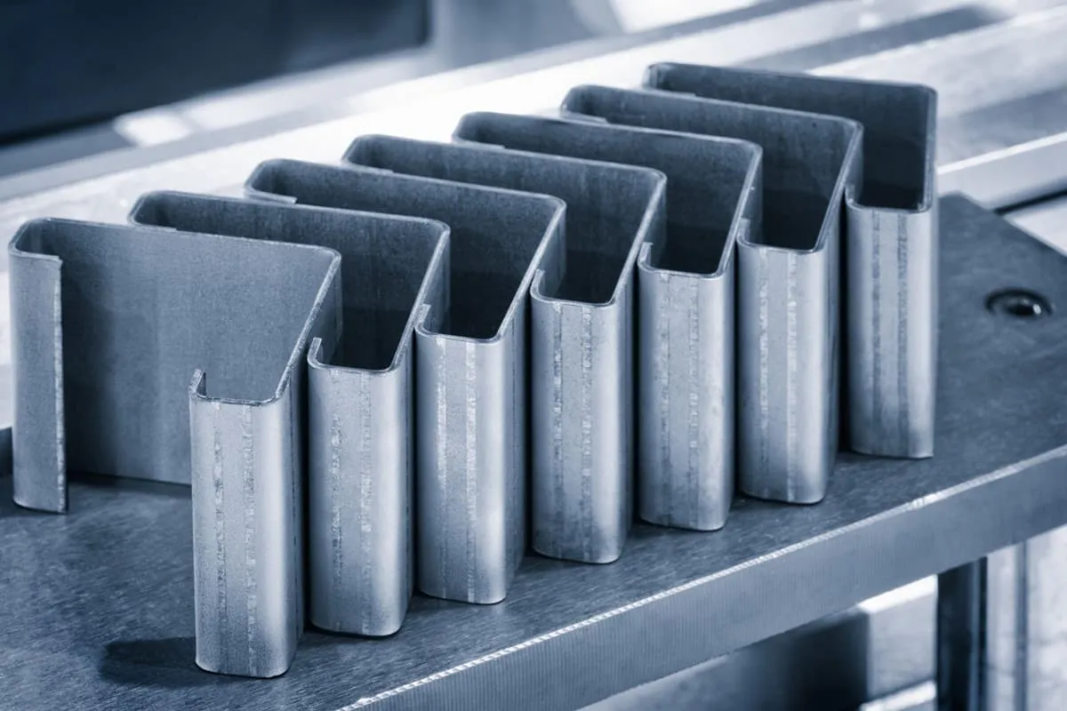
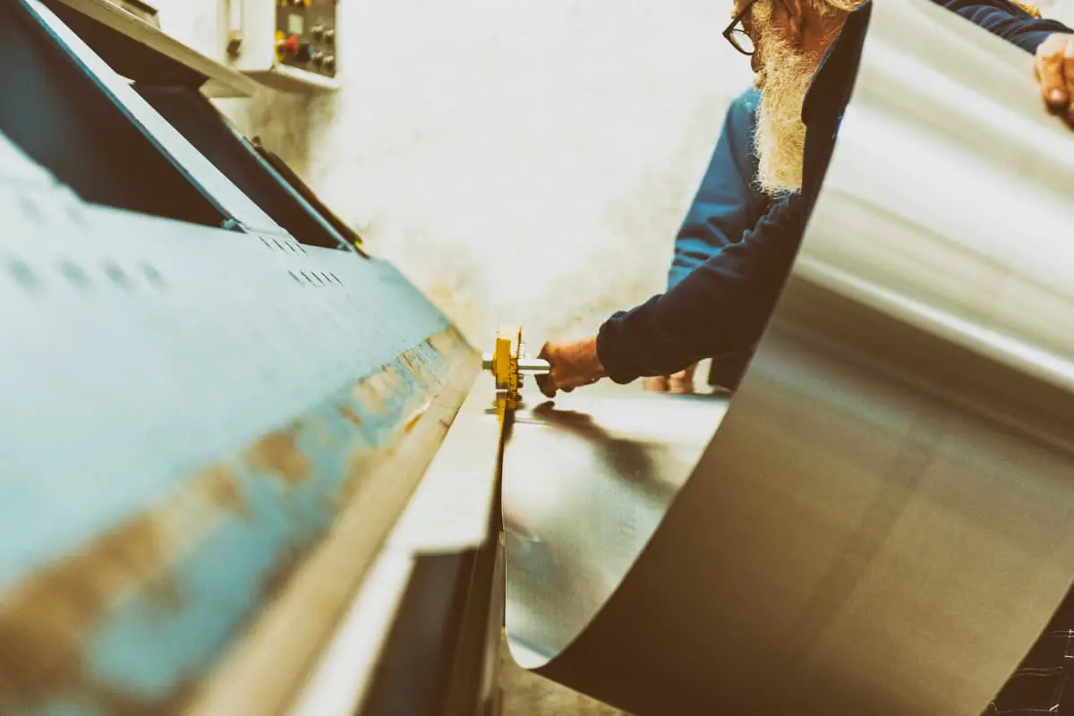
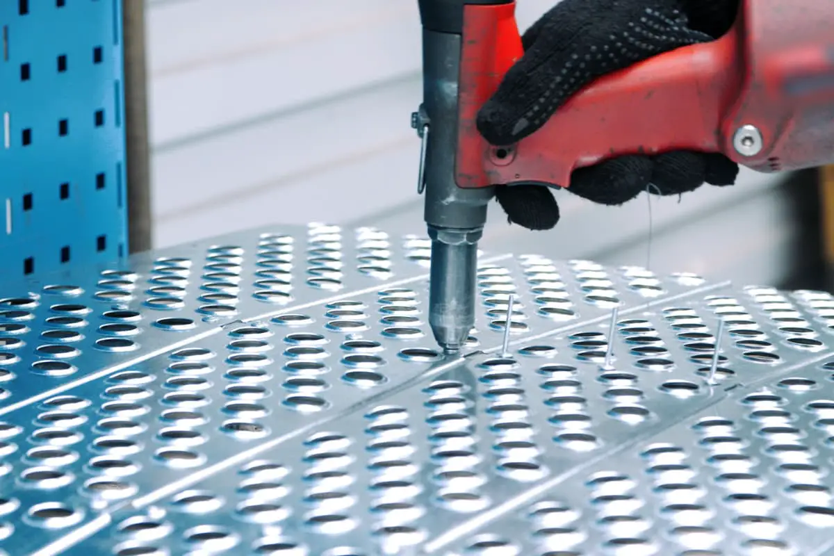
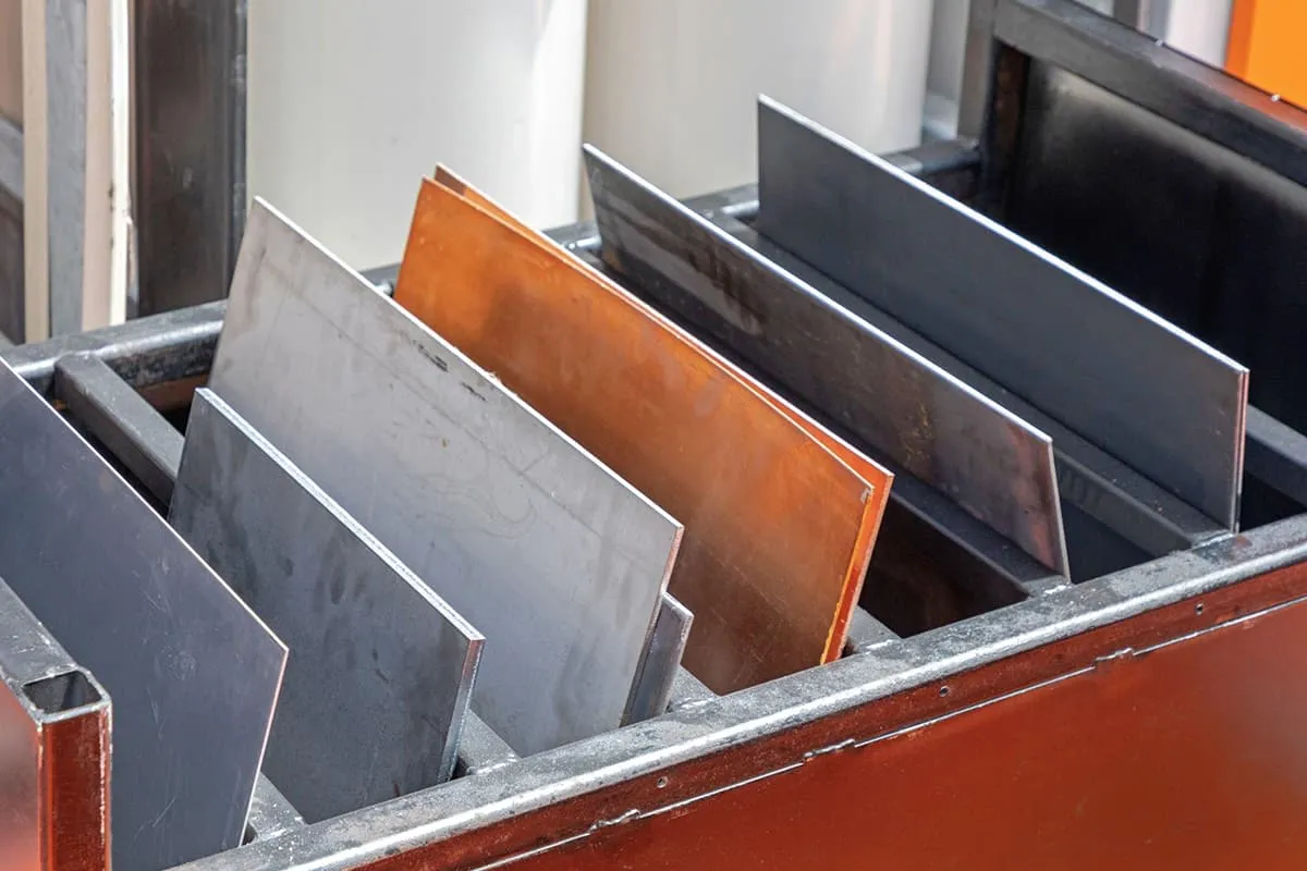
Sheet metal parts generally refer to the use of the metal’s plasticity to manufacture individual parts with a certain thickness of metal sheet through processes like shearing, stamping, bending, etc., and then assembling them into complete parts through welding, riveting, and other methods. The characteristic feature is the uniform thickness of the parts.
Due to its light weight, high strength, conductivity, low cost, and good performance in mass production, sheet metal parts have been widely used in fields such as petrochemicals, metallurgy, electronics, communications, automotive industries, and medical devices. For example, in everyday products like computer cases, mobile phones, MP3 players, sheet metal parts are essential components.
With the increasing widespread application of sheet metal, the design of sheet metal parts has become an important part of the product development process. Mechanical engineers must be proficient in the design techniques of sheet metal parts, ensuring that the designed sheet metal parts meet the requirements of product function, appearance, as well as production and processing convenience and cost-effectiveness.
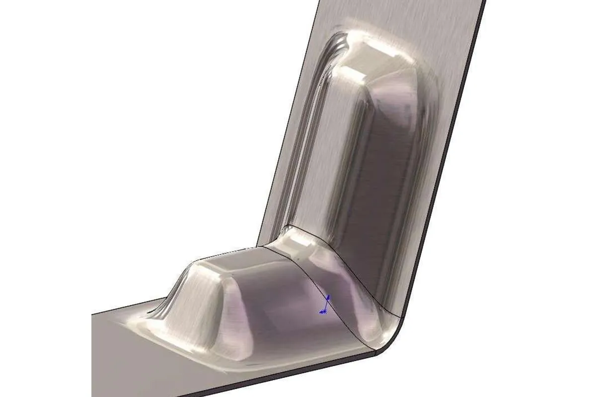
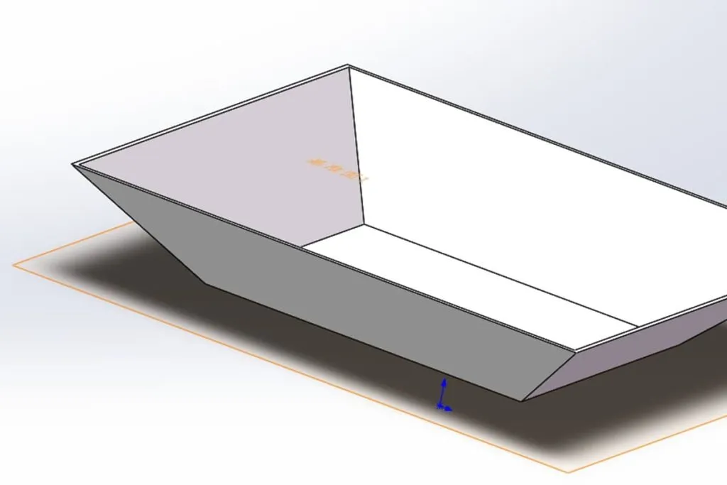
In the design process of sheet metal parts, in addition to expressing the shape and size of the parts using engineering drawings, it is also necessary to use the unfolded drawing of the sheet metal to represent the profile shape and size of the sheet metal parts before production and processing. This is used to guide the cutting, layout, and production of sheet metal parts.
This process of drawing the flattened contour based on the three-dimensional shape requirements of the part is known as the unfolding and layout of sheet metal parts. Mastering the correct and effective method of unfolding and laying out sheet metal parts can ensure the accuracy of the parts and improve processing efficiency, thus saving costs.
The traditional method of sheet metal unfolding involves using principles of descriptive and analytic geometry to flatten the three-dimensional sheet metal part onto a plane and create an unfolded drawing. The surface shapes of sheet metal can be divided into two major categories: theoretically developable surfaces and non-developable surfaces.
Developable surfaces refer to planes, cylindrical surfaces, conical surfaces, or surfaces segmented by these curves.
Non-developable surfaces refer to spherical surfaces, toroidal surfaces, and other irregular surfaces. Developable surfaces can theoretically be accurately unfolded, where the lengths of corresponding elements in the three-dimensional projected view and the unfolded view are equal, and the surface area of the part remains consistent before and after unfolding.
Non-developable surfaces theoretically cannot be unfolded onto a plane directly; they can only be approximated by dividing the object into multiple developable surface patches and then unfolding them. Traditional methods of sheet metal unfolding include template calculation, projection drawing, and software-assisted methods.
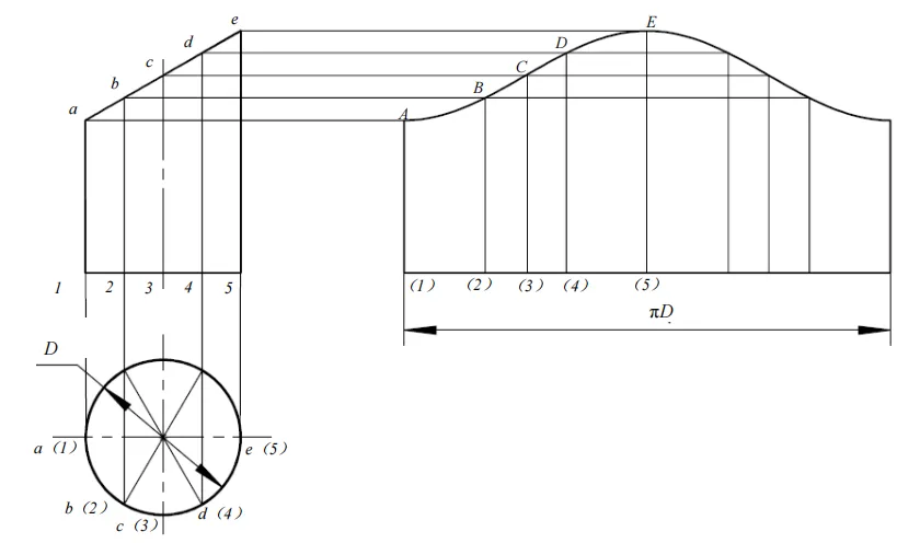
The projection drawing method involves using descriptive geometry and manual drawing to unfold the sheet metal part. Specific methods include the parallel line method, the radial line method, and the triangular line method.
The parallel line method is generally used for unfolding cylindrical surfaces, the radial line method is used for unfolding conical surfaces, and the triangular line method is used for the approximate unfolding of non-developable surfaces.
The template calculation method involves using principles of analytic geometry to calculate the unfolding of sheet metal parts. Specific methods include the actual length calculation method and the coordinate calculation method. The actual length calculation method calculates the length of lines (elemental lines) using analytic geometry during unfolding and then uses this data to draw the unfolded view.
This method replaces the length reference based on graphical lines in the projection drawing method with more accurate data, resulting in a more precise outcome. However, the final outline of the unfolded drawing still needs to be completed by drawing, which may still have significant errors. The coordinate calculation method is similar in principle to the actual length calculation method.
When using the coordinate calculation method, the coordinates of various reference points in the unfolded contour are directly calculated relative to a certain coordinate system, and then the sheet metal unfolded contour is drawn in this coordinate system.
The software-assisted unfolding method is based on the principle of template calculation and uses software to automatically generate the unfolded drawing, resulting in a DXF/DWG format drawing that can be directly imported into AutoCAD for editing and modification.
However, the resulting drawing is generated in an ideal state and does not consider the actual production material thickness, and a complete three-dimensional model is not obtained.
The traditional methods for sheet metal unfolding are based on the theoretical zero-thickness ideal surface. In practical sheet metal design, however, the material has a certain thickness.
When the thickness of the sheet metal is small and precision requirements are not high, the thickness factor can be ignored. However, when precision is required, the calculation of the sheet metal unfolding must consider the thickness of the material. Therefore, traditional sheet metal unfolding methods are only suitable for hand-cutting production with low precision requirements.
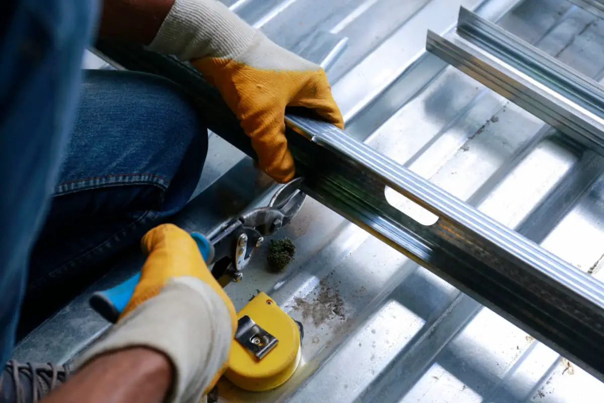
In recent years, with the widespread use of CNC punch presses, laser, plasma, water jet cutting machines, and CNC press brakes, the production and processing efficiency of sheet metal parts has greatly improved. This has led to updated and higher requirements for the design and unfolding of sheet metal parts.
The mainstream approach for sheet metal design now involves using 3D CAD/CAM technology. The idea is to directly design and model sheet metal parts or assemblies in a 3D environment, and then automatically unfold the sheet metal in the software.
This process can directly generate the orthographic views and unfolded views of the sheet metal parts, with the corresponding data being directly imported into various advanced processing equipment, providing data references for production and processing.
In popular 3D CAD software, such as CATIA, SolidWorks, UG, CREO, and SolidEdge, there are modules specifically designed for sheet metal design.