MIG vs SMAW: What’s the Difference?
Have you ever wondered why some welders choose MIG while others swear by SMAW? If you’re stepping into the world…
To achieve good welding results, it is necessary to choose reasonable welding parameters. The main parameters for shielded metal arc welding include the type and polarity of welding current, electrode diameter, welding current, arc voltage, welding speed, and number of welding layers. Structurally, it also includes the workpiece groove, and matters related to before and after welding.
The selection of welding current type mainly depends on the type of electrode coating, such as low-hydrogen sodium electrodes using direct current reverse polarity; low-hydrogen potassium electrodes and acidic electrodes require both direct and alternating current, generally using alternating current.
Polarity refers to the connection method of the positive and negative terminals of the direct current welding machine output. Connecting the workpiece to the positive terminal (welding clamp, electrode to the negative terminal) is called direct connection; connecting to the negative terminal is called reverse connection, low-hydrogen sodium and potassium electrodes use reverse connection. Acidic electrodes can use both alternating and direct current, direct or reverse connection; when using a direct current welding machine, use direct connection for thick plates and reverse connection for thin plates.
The relationship between electrode diameter and workpiece thickness is shown in Table 5-8. For the first layer of multi-layer welding with a groove and for welds in positions other than flat welding, a smaller electrode diameter than that used for flat welds should be used.
Table 5-8 Relationship between electrode diameter and workpiece thickness
| Workpiece thickness/mm | ≤1.5 | 2 | 3 | 4~5 | 6~12 | >13 |
| Electrode diameter/mm | 1.5 | 2 | 3.2 | 3.2 ~4 | 4~5 | 5~6 |
In order to obtain a larger molten pool during the welding process and reduce the dripping of molten metal, the electrode diameter used in flat welding positions is larger than that used in other welding positions under the same workpiece thickness. The maximum electrode diameter for vertical welding positions should not exceed 5mm, and the electrode diameter used for horizontal and overhead welding should not exceed 4mm.
The method is to consult a table or calculate.
1) Consult the table. Table 5-9 provides reference values for welding currents suitable for electrodes of various diameters.
Table 5-9 Reference values of welding current for electrodes of various diameters
| Electrode diameter/mm | 1.6 | 2 | 2.5 | 3.2 | 4 | 5 | 5.8 |
| Welding current/A | 25~40 | 40~65 | 50~80 | 100 ~130 | 160 ~210 | 200 ~270 | 260 ~300 |
2) Calculate using the following empirical formula:
I=(30 ~50)d
Where:
For flat welding, a larger current can be chosen for welding. For horizontal, vertical, and overhead welding, the welding current should be 10%~20% less than that for flat welding positions.
For root passes, especially for single-sided welding with double-sided formation, a smaller welding current should be chosen; for filling passes, a larger welding current can be used, and for cover passes, the current used should be slightly smaller.
There are several methods to determine if the selected current is appropriate:
1) Observe the spatter.
When the current is too high, large particles of liquid metal spatter out of the weld pool with loud popping sounds; when the current is too low, it is difficult to distinguish between slag and liquid metal.
2) Observe the weld formation.
When the current is too high, the penetration is deep, the weld sinks, and the sides of the weld are prone to undercutting; when the current is too low, the weld is narrow and tall, with poor fusion on the sides with the base material.
3) Observe the melting condition of the electrode.
When the current is too high, the electrode melts and turns red prematurely; when the current is too low, the arc is unstable, and the electrode tends to stick to the workpiece.
Arc voltage is mainly determined by the length of the arc. Generally, the arc length is 0.5 to 1 times the diameter of the electrode, with a corresponding arc voltage of 16 to 25V. For basic electrodes, the arc length should be half the diameter of the electrode, and for acidic electrodes, the arc length should be equal to the diameter of the electrode.
The welding speed can be flexibly controlled by the welder according to the specific situation, with the principle of ensuring that the weld seam has the required external dimensions and ensuring good fusion. When welding materials that have strict requirements on welding heat input, the welding speed should be controlled as specified in the process documents. During the welding process, the welder should adjust the welding speed at any time to ensure the consistency of the height and width of the weld seam.
If the welding speed is too slow, the weld seam will be too high or too narrow, and the shape will be irregular; when welding thin plates, it may even burn through; if the welding speed is too fast, the weld seam will be narrow, resulting in defects of incomplete penetration.
The principle for determining the number of welding layers is to ensure that the weld metal has sufficient plasticity. Under the condition of ensuring welding quality, use large diameter electrodes and high current for welding to improve labor productivity.
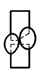
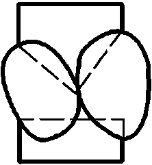
As shown in Figure 5-13, when performing multi-layer and multi-pass welding on low carbon steel and common low alloy structural steels such as Q345 (16Mn), the number of welding layers has little impact on the joint quality, but if the number of layers is too few and each layer of weld thickness is too large, it will have a certain impact on the plasticity of the weld metal. For other types of steel, multi-layer and multi-pass welding should be used, and the thickness of each layer of weld should generally be ≤4mm.
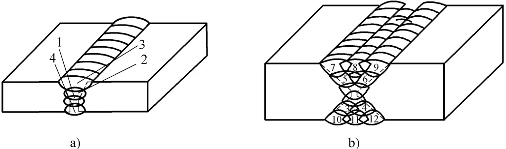
a) Multi-layer welding
b) Multi-layer multi-pass welding
1 ~ 12—Weld pass numbers
Welding heat input refers to the thermal energy input to the unit length of the weld by the welding energy source during fusion welding, and its calculation formula is as follows:
In the formula, q is the heat input per unit length of the weld (J/mm); I is the welding current (A); U is the arc voltage (V); v is the welding speed (mm/s); ???? is the thermal efficiency (for shielded metal arc welding ???? is 0.7~0.8; for submerged arc welding ???? is 0.8~0.95; for TIG ???? is 0.5).
Example: When welding Q345 (16Mn) steel, the required welding heat input should not exceed 28kJ/cm. If a welding current of 180A and an arc voltage of 28V are chosen, what should be the welding speed?
Solve I=180A; q=28kJ/cm; U=28V
Take ????=0.7
From:
It is known:
Therefore:
The welding speed to be used should be 0.126cm/s.
Heat input has little effect on the performance of low carbon steel welded joints, therefore, for shielded metal arc welding of low carbon steel, heat input is generally not specified. For low alloy steel and stainless steel, excessive heat input will affect the performance of the welded joints; too little heat input may cause cracking defects in some steels during the welding process, therefore, the welding process for these steels should specify heat input.
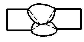
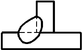
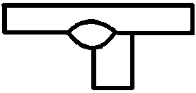
In the process of shielded metal arc welding, due to different welding structural forms, different thicknesses of the workpieces, and different welding quality requirements, the joint forms and groove forms also vary. Common joint forms include butt joint, lap joint, corner joint, T-joint, and end joint. Common welding groove forms and sizes are shown in Figure 5-14.
See Table 5-10 for electrode arc welding parameters in different states.
Table 5-10 Electrode arc welding parameters in different states
| Weld seam spatial position | Weld seam cross-sectional shape | Thickness of the workpiece or weld Leg size /mm | First layer of weld | Other layers of weld | Backing weld seam | |||
| Electrode Diameter /mm | Welding Current /A | Electrode Diameter /mm | Welding Current /A | Electrode Diameter /mm | Welding Current /A | |||
| Flat Butt Weld | 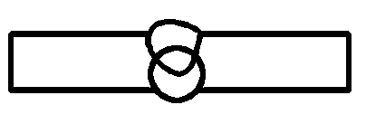 | 2 | 2 | 55~60 | — | — | 2 | 55~60 |
| 2.5~3.5 | 3.2 | 90 ~120 | — | — | 3.2 | 90 ~120 | ||
| 4 ~5 | 3.2 | 100~130 | — | — | 3.2 | 100 ~130 | ||
| 4 | 160 ~200 | — | — | 4 | 160 ~210 | |||
| 5 | 200 ~260 | — | — | 5 | 220~250 | |||
 | 5 ~6 | 4 | 160 ~210 | — | — | 3.2 | 100 ~130 | |
| 4 | 180 ~210 | |||||||
| ≥8 | 4 | 160 ~210 | 4 | 160 ~210 | 4 | 180 ~210 | ||
| 5 | 220 ~280 | 5 | 220~260 | |||||
 | ≥12 | 4 | 160 ~210 | 4 | 160 ~210 | — | — | |
| 5 | 220 ~280 | — | — | |||||
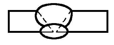
| Vertical Butt Weld | 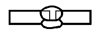 | 2 | 2 | 50~55 | — | — | 2 | 50~55 |
| 2.5~4 | 3.2 | 80 ~110 | — | — | 3.2 | 80 ~110 | ||
 | 5~6 | 3.2 | 90 ~120 | — | — | 3.2 | 90 ~120 | |
| 7 ~10 | 3.2 | 90 ~120 | 4 | 120 ~160 | 3.2 | 90 ~120 | ||
| 4 | 120 ~160 | 3.2 | 90 ~120 | |||||
| ≥11 | 3.2 | 90 ~120 | 4 | 120 ~160 | 3.2 | 90 ~120 | ||
| 4 | 120 ~160 | 5 | 160 ~200 | |||||
 | 12 ~18 | 3.2 | 90 ~120 | 4 | 120 ~160 | — | — | |
| 4 | 120 ~160 | |||||||
| ≥19 | 3.2 | 90 ~120 | 4 | 120 ~160 | — | — | ||
| 4 | 120 ~160 | 5 | 160 ~200 | |||||
| Horizontal Butt Weld | 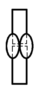 | 2 | 2 | 50~55 | — | — | 2 | 50~55 |
| 2.5 | 3.2 | 80 ~110 | — | — | 3.2 | 80 ~110 | ||
| 3 ~4 | 3.2 | 90 ~120 | — | — | 3.2 | 90~120 | ||
| 4 | 120 ~160 | — | — | 4 | 120 ~160 | |||
 | 5 ~8 | 3.2 | 90 ~120 | 3.2 | 90 ~ 120 | 3.2 | 90 ~ 120 | |
| 4 | 140 ~ 160 | 4 | 120 ~160 | |||||
| ≥9 | 3.2 | 90 ~120 | 4 | 140 ~ 160 | 3.2 | 90~120 | ||
| 4 | 140 ~160 | 4 | 120 ~160 | |||||
 | 14 ~18 | 3.2 | 90 ~120 | 4 | 140 ~ 160 | — | — | |
| 4 | 140 ~160 | |||||||
| ≥19 | 4 | 140 ~160 | 4 | 140 ~ 160 | — | — | ||
| Overhead Butt Weld |  | 2 | — | — | — | — | 2 | 50 ~ 65 |
| 2.5 | — | — | — | — | 3.2 | 80 ~110 | ||
| 3 ~5 | — | — | — | — | 3.2 | 90 ~110 | ||
| 4 | 120 ~160 | |||||||
 | 5 ~8 | 3. 2 | 90 ~ 120 | 3.2 | 90 ~ 120 | — | — | |
| 4 | 140 ~ 160 | |||||||
| ≥9 | 3. 2 | 90 ~ 120 | 4 | 140 ~ 160 | — | — | ||
| 4 | 140 ~160 | |||||||
 | 12 ~18 | 3.2 | 90 ~120 | 4 | 140 ~ 160 | — | — | |
| 4 | 140 ~ 160 | |||||||
| ≥19 | 4 | 140 ~160 | 4 | 140 ~ 160 | — | — | ||
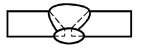
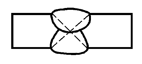
| Flat angle butt weld | 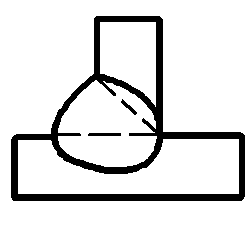 | 2 | 2 | 55~65 | — | — | — | — |
| 3 | 3.2 | 100 ~120 | — | — | — | — | ||
| 4 | 3.2 | 100~120 | — | — | — | — | ||
| 4 | 160 ~200 | — | — | — | — | |||
| 5 ~6 | 4 | 160 ~200 | — | — | — | — | ||
| 5 | 220~280 | — | — | — | — | |||
| ≥7 | 4 | 160~200 | 5 | 220~230 | — | — | ||
| 5 | 220~280 | 5 | 220 ~230 | — | — | |||
 | — | 4 | 160 ~200 | 4 | 160 ~200 | 4 | 160 ~220 | |
| 5 | 220 ~280 | |||||||
| Vertical angle butt weld | 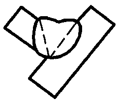 | 2 | 2 | 50 ~ 60 | — | — | — | — |
| 3 ~4 | 3.2 | 90 ~120 | ||||||
| 5 ~8 | 3.2 | 90 ~120 | — | — | — | — | ||
| 4 | 120 ~160 | |||||||
| 9 ~12 | 3.2 | 90 ~120 | 4 | 120 ~160 | — | — | ||
| 4 | 120~160 | |||||||
| Vertical angle butt weld | 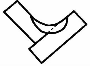 | — | 3.2 | 90 ~120 | 4 | 120 ~160 | 3.2 | 90 ~120 |
| 4 | 120 ~160 | |||||||
| Overhead angle butt weld | 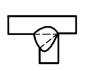 | 2 | 2 | 50 ~60 | — | — | — | — |
| 3 ~4 | 3.2 | 90 ~120 | — | — | — | — | ||
| 5~6 | 4 | 120 ~ 160 | — | — | — | — | ||
| ≥7 | 4 | 140 ~160 | 4 | 140 ~160 | — | — | ||
 | — | 3.2 | 90 ~120 | 4 | 140 ~160 | 3.2 | 90 ~ 120 | |
| 4 | 140 ~ 160 | 4 | 140 ~160 | |||||