Submerged Arc Welding: Principles, Features & Applications
Welcome to the world of Submerged Arc Welding (SAW). This article will explore how SAW works, its benefits and limitations,…
Are you ready to elevate your welding game with submerged arc welding (SAW)? This technique, celebrated for its efficiency and precision, can revolutionize your projects. In this article, you’ll discover the essential preparation steps, key welding parameters, and expert tips to ensure flawless results. From groove processing to the perfect welding speed, we’ve got you covered. Dive in to master the art of submerged arc welding and achieve impeccable, high-quality welds every time.
When welding, due to the use of high current, when the thickness of the steel plate is less than 14mm, it is generally not necessary to groove, but when the thickness is greater than 14mm, in order to ensure the quality of welding, a certain form of groove should be made. For carbon steel and low alloy steel submerged arc welding joints, grooves should be made according to the provisions of GB/T985.2-2008 “Recommended Grooves for Submerged Arc Welding”.
Groove processing can be done using equipment such as edge planers, gas cutting machines, or carbon arc gouging, and the processed groove edges must be straight and meet the specified technical requirements.
Before welding, it is necessary to clean the groove and the area 20~50mm on both sides of the groove of etching, oil, moisture, oxides, etc. Cleaning methods can include steel wire brushes, wire wheels, portable grinders, polishing machines, shot blasting, and oxy-fuel flame baking.
The assembly of weldments requires high precision, ensuring uniform gaps, level surfaces, and no misalignment.
Submerged arc welding wire and flux participate in the welding metallurgical reaction, greatly affecting the composition, structure, and mechanical properties of the weld. Therefore, it is necessary to enhance the cleaning of the welding wire and dry the flux before welding.
1) The welding wires sold in the market generally have an anti-rust copper coating.
Before use, it is necessary to remove oil and other contaminants from the surface of the welding wire to prevent hydrogen pores. If the welding wire does not have an anti-rust copper coating, it is also necessary to remove rust and oxide scale from the surface before welding.
2) The flux should be dried as required before use.
Acidic flux should be dried at 250°C and kept warm for 1~2 hours; high fluoride flux that is limited to direct current must be dried at 300~400°C and kept warm for 2 hours, and should be used immediately after drying.
As much as possible, fixtures should be used during pre-weld assembly to ensure the accuracy of tack welding. Generally, the fixtures are removed after tack welding. If welding needs to be performed with fixtures, the fixtures must not interfere with the welding process. Light and thin workpieces should be fixed using fixtures or tack welding; workpieces of medium thickness or greater must be fixed using tack welding.
The tack weld seam should be on the back of the first weld seam, and the length and spacing of the tack weld seam should be determined based on the thickness of the plate. When the thickness of the welded part is <3mm, the tack weld seam is 30~40mm long, spaced 250~300mm; when the thickness of the welded part is 3~25mm, the tack weld seam is 40~50mm long, spaced 300~500mm; when the thickness of the welded part is >25mm, the tack weld seam is 50~60mm long, spaced 250~300mm.
Tack welding generally uses the shielded metal arc welding method. The welding materials used for tack welding should match the performance of the workpiece materials. After tack welding, the slag shell and spatter on the weld seam should be promptly cleaned, and checked for cracks and other excessive defects, if found, they should be chiseled out and re-tack welded. When welding straight seams, a start plate and a run-off plate should be added, with the same thickness as the workpiece, 100~150mm long and 70~100mm wide.
The main welding parameters for submerged arc welding include welding current, welding voltage, welding speed, power source and polarity, wire diameter, and the length of wire protruding from the contact tip.
The depth of the weld pool in automatic submerged arc welding (referred to as penetration depth) is determined by the welding current, and its approximate empirical formula is
h =ki
where:
Welding current is the main factor determining the penetration depth. Within a certain range, as the welding current increases, both the penetration depth and reinforcement of the weld increase, while the width of the weld does not increase significantly.
Increasing the welding current can improve productivity, but at a certain welding speed, excessive welding current will cause the heat-affected zone to be too large and produce defects such as weld lumps and burn-through; if the welding current is too small, the penetration is insufficient, which can lead to poor fusion, incomplete penetration, slag inclusion, and poor weld formation.
To ensure the aesthetic formation of the weld, while increasing the welding current, it is necessary to increase the arc voltage to maintain an appropriate proportional relationship, see Table 5-35 for the corresponding welding voltage.
Table 5-35 Corresponding welding voltage for welding current
| Welding current/A | 600~700 | 700 ~ 850 | 850~1000 | 1000 ~ 1200 |
| Welding voltage/V | 36~38 | 38~40 | 40 ~ 42 | 42~44 |
Welding voltage is the main factor determining the width of the melt. When the welding voltage is increased, the arc length increases, the depth of penetration decreases, the weld becomes wider, and the excess height decreases. If the welding voltage is too high, the amount of flux melted increases, the arc becomes unstable, and defects such as undercut and porosity may occur. Therefore, while increasing the welding voltage, it is also appropriate to increase the welding current.
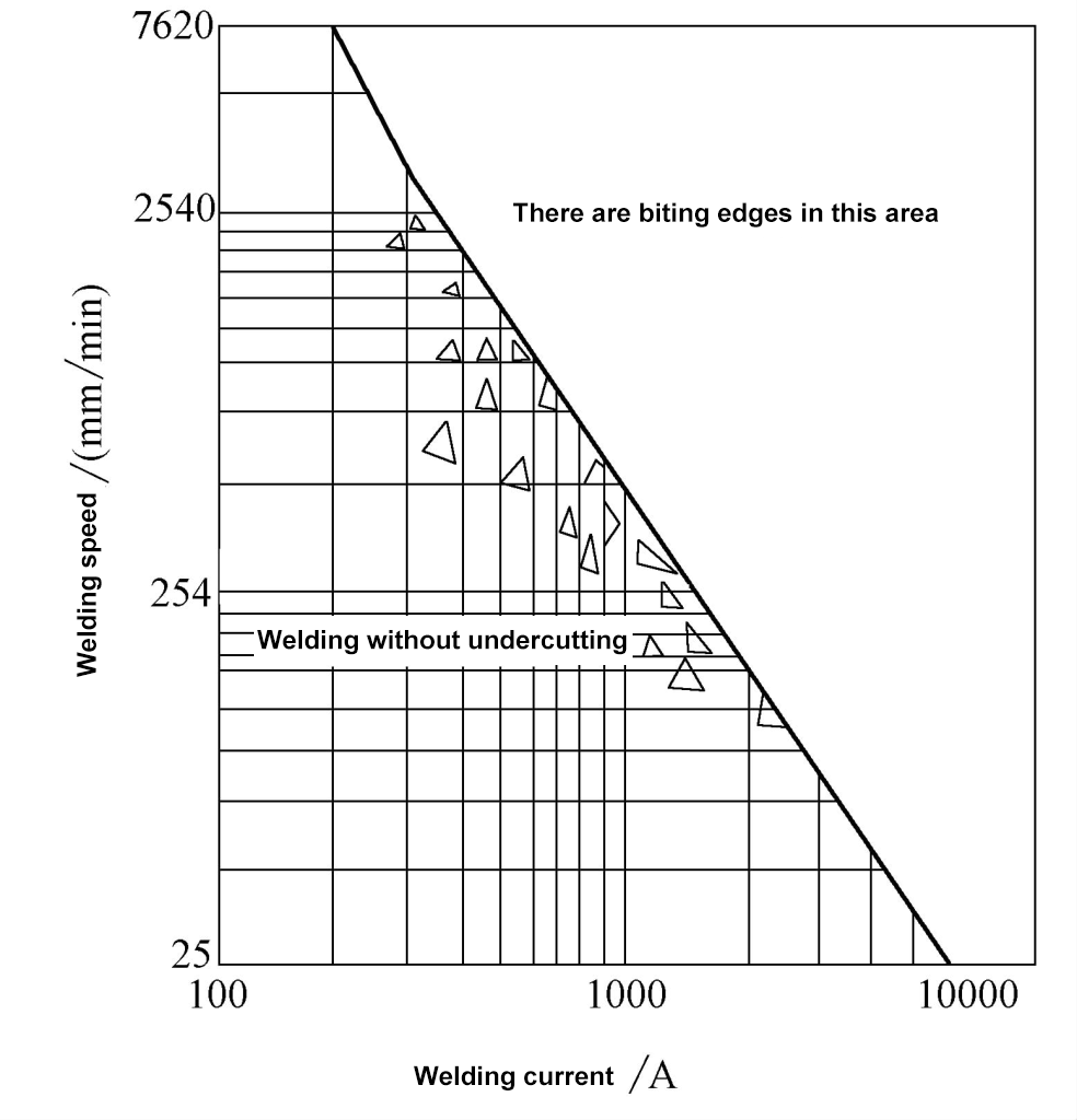
Welding speed has a significant impact on both depth and width of penetration. When the welding speed is increased, both the depth and width of penetration decrease. Therefore, to ensure penetration and increase welding speed, it is necessary to simultaneously increase both welding current and voltage. However, too high a current and too fast a welding speed can cause defects such as undercut, incomplete penetration, arc blow, and porosity. Conversely, too slow a welding speed results in excessive excess height, forming a large molten pool, overflow, rough weld formation, and slag inclusion. Therefore, the welding speed should neither be too high nor too low.
The matching relationship between welding current and welding speed is shown in Figure 5-43. For a certain welding current, there is an appropriate range of welding speeds within which the weld formation is aesthetic; when the welding speed exceeds the upper limit of this range, defects such as undercut will occur. When the welding speed is below the lower limit of this range, defects such as slag inclusion will occur.
1) External characteristics.
Use a dropping external characteristic. When using a submerged arc welding machine with constant speed wire feeding, a slowly dropping characteristic should be used; when using a welding machine with an automatic arc adjustment system, a steeply dropping characteristic should be used. For welding thin plates with fine wire, a DC flat characteristic power source should be used.
2) Polarity.
DC reverse polarity is usually used, and for build-up welding, DC straight polarity should be used.
With a fixed current, the finer the wire diameter, the deeper the penetration, and the smaller the weld formation factor. However, for a certain wire diameter, the range of current used should not be too large, otherwise, the wire will turn red due to excessive resistance heat, affecting the performance of the wire and the stability of the welding process. The welding current range for different diameters of wire is shown in Table 5-36.
Table 5-36 Welding current range for different wire diameters
| Wire diameter/mm | 2 | 3 | 4 | 5 | 6 |
| Current density / (A/mm²) | 63~125 | 50~85 | 40 ~63 | 35~50 | 28~42 |
| Welding current / A | 200 ~400 | 350 ~600 | 500 ~ 800 | 700~1000 | 800~1200 |
Increasing the protrusion length of the wire increases the resistance, speeds up the melting of the wire, and increases the excess height. If the protrusion length is too small, the protruding part of the wire turns red, or even melts in sections; if the protrusion length is too short, the heat generated by the arc can easily damage the conductive nozzle. The general protrusion length of the wire is 30~40mm.
In single wire submerged arc welding, the wire is generally perpendicular to the workpiece, but in double or triple wire welding, since each wire has a different function, a certain angle of inclination is appropriate. When the wire is inclined forward (the angle between the wire and the welding direction is 90°), the penetration significantly decreases, and the weld formation is poor, generally only used for the leading wire in multi-wire welding. When the wire is inclined backward, the penetration increases, the excess height increases, and the weld is deep and narrow.
If the flux layer thickness is too small, the arc protection is poor, and even open arc occurs, causing unstable arc, prone to porosity and cracks. If the flux layer thickness is too large, it makes the weld narrower, and the weld shape factor decreases (the weld shape factor is the ratio of weld width to penetration, denoted by ψ). The general thickness of the flux layer is 20~30mm.
Increasing the granularity of the flux decreases the penetration slightly, increases the width slightly, and also slightly reduces the excess height. When the granularity of the flux is fixed, if the current is too high, it can cause unstable arc and uneven edges of the weld bead. When the welding current is less than 600A, the granularity of the flux is 0.25~1.6mm; when the welding current is 600~
1200A, the granularity of the flux is 0.4~2.5mm; when the welding current is greater than 1200A, the granularity of the flux is 1.6~3.0mm.
1) Groove shape.
When other welding parameters remain unchanged, increasing the depth and width of the groove increases the depth of penetration of the weld, significantly reducing the weld reinforcement and fusion ratio.
2) Root gap.
In butt welds, increasing the root gap of the workpieces also increases the depth of penetration.
3) Thickness of the workpieces and heat dissipation conditions.
When the thickness of the workpieces is greater and the heat dissipation conditions are better, the width of the weld will decrease, and the reinforcement will increase.
The impact of welding parameters on weld quality and formation is shown in Table 5-37.
Table 5-37 Impact of welding parameters on weld quality and formation
| Welding Parameters | Impact on Weld Quality and Formation | Schematic Diagram |
| Welding Current I | 1. Within a certain range, an increase in I increases both the depth of fusion and the reinforcement, improving productivity 2. When welding speed is constant, too high I can cause burn-through and an excessively large heat-affected zone 3. Too low I results in insufficient penetration and defects such as poor fusion, lack of penetration, and slag inclusion, worsening the weld formation | 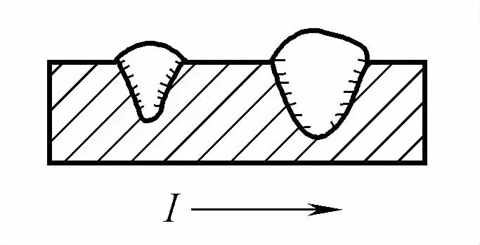 |
| Arc Voltage U | 1. An increase in U decreases the depth of fusion and reinforcement, widening the weld 2. Too high U increases the amount of flux melted, disrupts the arc, and can also cause defects such as porosity in the weld | 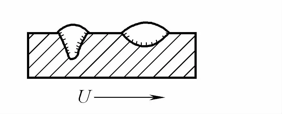 |
| Welding speed v | 1. As v increases, the base material melting ratio ① decreases 2. Too high v can easily cause defects such as undercut, incomplete penetration, arc blow, and porosity, resulting in poor weld formation 3. Too slow v results in excessive reinforcement, wide and shallow weld pool, rough weld surface, prone to overflow, weld lumps or burn-through; if U is also too high, it can easily cause cracking | 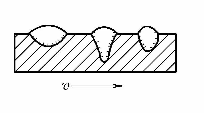 |
| Wire diameter and stick-out length | 1. With constant I, reducing wire diameter increases penetration depth, and the weld formation factor ② decreases 2. Increasing wire stick-out length increases deposition rate ③ and reinforcement | — |
| Wire angle (wire to workpiece) | 1. In single wire welding, the wire is perpendicular to the workpiece 2. When the wire is tilted forward, the penetration is shallow, the weld is wide, suitable for welding thin plates When the welding wire is tilted backwards, the penetration and excess height increase, the weld width significantly decreases, and the weld formation is poor; generally only used for the leading welding wire in multi-wire welding. | 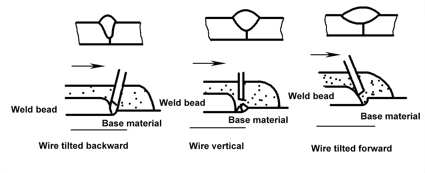 |
| Weldment tilt angle | 1. During uphill welding, the penetration and excess height are large, the weld width is narrow, and when the uphill angle is too large, the excess height is too large and easily causes undercutting. 2. During downhill welding, the penetration and excess height decrease, the weld width increases, and an excessive tilt angle can cause insufficient penetration and weld overflow. | 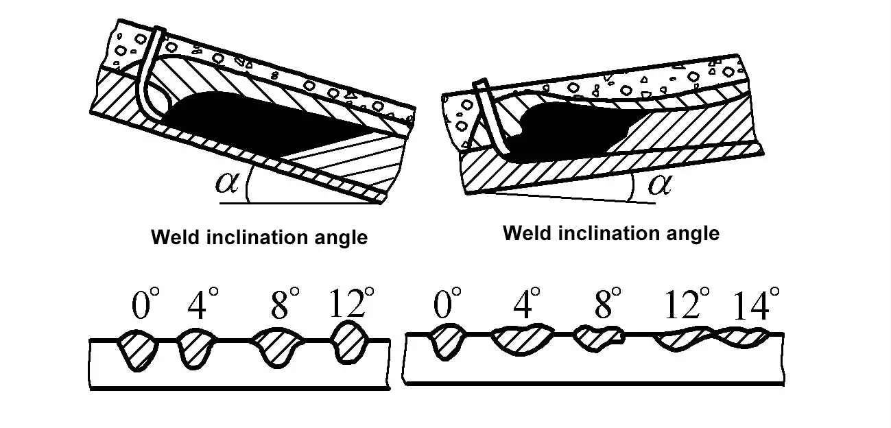 |
| Assembly gap and groove angle | When the assembly gap and groove angle increase while other conditions remain unchanged, the excess height h decreases, while the penetration depth H increases, and the welding thickness h + H remains roughly unchanged. | 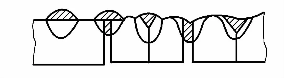 |
| Flux layer thickness and granularity | 1. If the flux layer is too thin, the arc is exposed, arc protection is poor, and it is easy to produce pores or cracks; if too thick, the weld becomes narrower, and the weld formation factor decreases. 2. When welding thin plates with fine welding wire, if the flux particles are too large, the arc is unstable, and the weld surface is rough; when the particles are small, the weld surface is smooth and well-formed. | — |
① Melting ratio: During fusion welding, the percentage of the base material that is melted in the weld metal.
② Weld formation factor: During fusion welding, the ratio of the weld thickness to the calculated weld thickness on the cross-section of a single weld pass.
③ Deposition rate: The amount of metal deposited on the workpiece per unit time during the deposition process (kg/h).
1) Single-sided welding with double-sided formation.
① Flux backing method.
The flux backing supports the back of the workpiece with a certain pressure to help form the weld. The submerged arc welding parameters for single-sided welding with double-sided formation on flux backing are shown in Table 5-38. Since the flux must always be in close contact with the workpiece during welding, and the backside formation of the weld is difficult to stabilize, to prevent the weld from hanging and the backing from not sticking tightly, it is generally pressed with a pressure frame, electromagnetic platform, etc.
Table 5-38 Welding parameters for single-sided welding with double-sided formation on flux backing in submerged arc welding
| Workpiece thickness/mm | Assembly gap/mm | Welding wire diameter/mm | Welding current/A | Arc voltage/V | Welding speed/(m/h) | Flux pad pressure/MPa |
| 2 | 0 ~1.0 | 1.6 | 120 | 24 to 28 | 43.5 | 8 |
| 3 | 0 ~1.5 | 2~3 | 275~300 400~425 | 28~30 25~28 | 44.7 | 8 |
| 4 | 0~1.5 | 2~4 | 375~400 525~550 | 28~30 | 40, 50 | 10~15 |
| 5 | 0 ~2.5 | 2~4 | 425~450 575~625 | 32~34 28~32 | 35, 46 | 10~15 |
| 6 | 0~3.0 | 2~4 | 475, 600 ~650 | 32~34 28~32 | 30, 40.5 | 10~15 |
| 7 | 0~3.0 | 4 | 650~700 | 30~34 | 37 | 10~15 |
| 8 | 0~3.5 | 4 | 725~775 | 30~36 | 34 | 10 ~15 |
Copper pad method and flux-copper pad method.
When welding thin plates of 4mm or less, assembly gaps can be omitted and welded directly on the copper backing plate to achieve single-side welding and double-side formation. When welding thicker plates, the flux-copper pad method is often used to improve the backside formation conditions.
At this time, the workpiece does not have a bevel, an appropriate assembly gap is reserved, and then flux is evenly sprinkled in the joint for welding. During welding, the workpiece must be tightly clamped against the copper backing plate. See Table 5-39 for the welding parameters for single-side butt welding on the flux copper backing plate.
Table 5-39 Welding parameters for single-side butt welding on the flux copper backing plate.
| Copper backing plate type | Steel plate thickness /mm | Assembly gap /mm | Welding wire diameter /mm | Welding current /A | Arc voltage /V | Welding speed /(cm/min) | Copper backing plate groove size /mm | ||
| b | h | r | |||||||
 | 3 | 2 | 3 | 380~420 | 27~29 | 78.3 | 10 | 2.5 | 7 |
| 4 | 2~3 | 4 | 450~500 | 29 ~31 | 68 | ||||
| 5 | 2~3 | 4 | 520~560 | 31~33 | 63 | ||||
| 6 | 3 | 4 | 550~600 | 33~35 | 63 | ||||
| 7 | 3 | 4 | 640~680 | 35~37 | 58 | 12 | 3 | 7.5 | |
| 8 | 3~4 | 4 | 680~720 | 35~37 | 53.3 | ||||
| 9 | 3~4 | 4 | 720~780 | 36~38 | 46 | 14 | 3.5 | 9.5 | |
| 10 | 4 | 4 | 780~820 | 38~40 | 46 | ||||
| 12 | 5 | 4 | 850~900 | 39~41 | 38 | 18 | 4 | 12 | |
| 14 | 5 | 4 | 880~920 | 39 ~41 | 36 | ||||
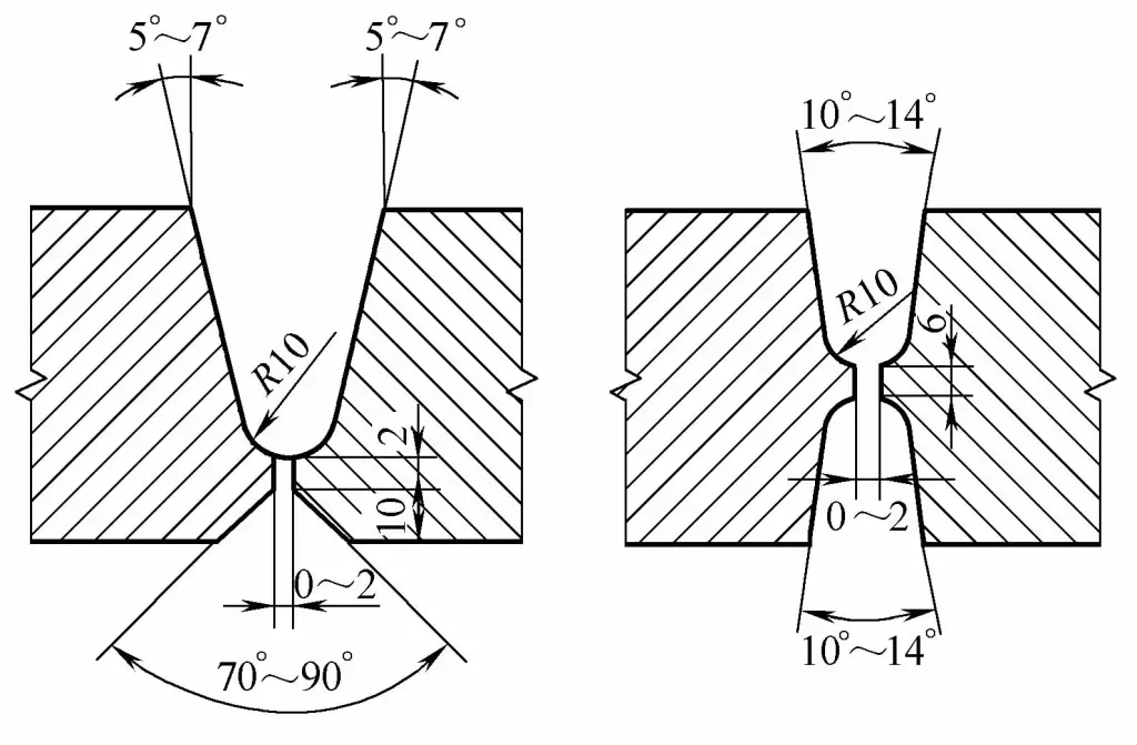
Electromagnetic platform with flux pad method.
For butt joint plates thinner than 14mm, single-side full penetration welding is possible. For thicknesses over 14mm, a bevel or gap should be used. A gap of 5~6mm allows for full penetration welding of 20mm without a bevel.
It should be noted that the purpose of beveling is not entirely to increase the amount of single-pass weld penetration; it also plays a significant role in controlling the fusion ratio and adjusting the weld reinforcement.
Table 5-40 Electromagnetic platform—Welding parameters for single-sided butt welding on a flux pad
| Plate thickness/mm | Assembly gap/mm | Wire diameter/mm | Welding current/A | Arc voltage/V | Welding speed/(cm/min) | Type of current | Flux particles in the flux pad | Air pressure in the flux pad hose /kPa |
| 2 | 0 ~1.0 | 1.6 | 120 | 24~28 | 73 | Direct current (reverse connection) | Tiny | 81 |
| 3 | 0~1.5 | 1.6 | 275~300 | 28~30 | 56.7 | AC | Tiny | 81 |
| 2 | 275~300 | 28~30 | 56.7 | |||||
| 3 | 400~425 | 25~28 | 117 | |||||
| 4 | 0~1.5 | 2 | 375~400 | 28~30 | 66.7 | AC | Tiny | 101-152 |
| 4 | 525~550 | 28~30 | 83.3 | 101 | ||||
| 5 | 0~2.5 | 2 | 425~450 | 32~34 | 58.3 | AC | Tiny | 101-152 |
| 4 | 575~625 | 28~30 | 76.7 | 101 | ||||
| 6 | 0~3.0 | 2 | 475 | 32~34 | 50 | AC | Normal | 101-152 |
| 4 | 600~650 | 28~32 | 67.5 | |||||
| 7 | 0~3.0 | 4 | 650~700 | 30~34 | 61.7 | AC | Normal | 101-152 |
| 8 | 0~3.5 | 4 | 725~775 | 30~36 | 56.7 | AC | Normal | 101-152 |
④ Gantry press frame flux copper pad method.
There are multiple cylinders on the crossbeam of the gantry press frame. After compressed air is introduced, the cylinders drive the clamping device to press the workpiece onto the flux copper pad for welding. After welding, the cylinders drive the clamping device through a three-way valve to lift and remove the workpiece.
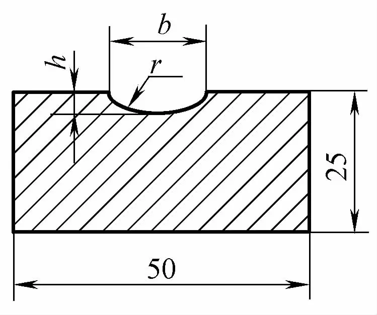
The forming device on the back of the weld uses a flux copper pad, with a forming groove on the copper pad to ensure backside forming. The cross-sectional shape of the copper liner forming groove is shown in Figure 5-44, and the cross-sectional dimensions of the flux copper pad are shown in Table 5-41.
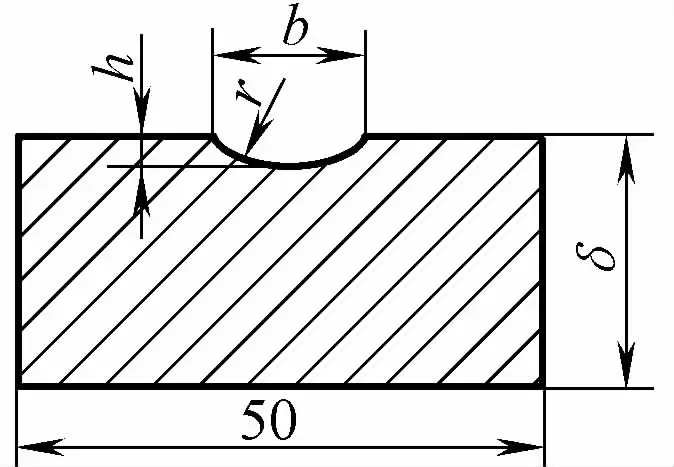
Table 5-41 Flux copper pad cross-sectional dimensions (unit: mm)
| Weldment Thickness | Copper Pad Width | Copper Pad Thickness | Groove width b | Groove depth h | Groove Curvature Radius r |
| 4~6 | 50 | 10 | 10 | 2.5 | 7 |
| 6~8 | 50 | 12 | 12 | 3 | 7.5 |
| 8 ~10 | 50 | 14 | 14 | 3.5 | 9.5 |
| 12 ~14 | 50 | 18 | 18 | 4 | 12 |
Clean the welding area, use the conveyor rollers on the welding platform to feed the weldment for assembly, leave a certain assembly gap and align the gap’s centerline with the centerline of the forming groove, weld the arc initiation plate and lead-out plate at both ends of the weld, lower the gantry to press the weldment, tighten the copper pad, fill the forming groove of the copper pad evenly with fine welding flux before welding, and then weld according to the prescribed welding parameters. See Table 5-42 for gantry pressure frame flux copper pad welding parameters.
Table 5-42 Gantry Pressure Frame—Flux Copper Pad Welding Parameters
| Weldment Thickness /mm | Assembly gap/mm | Wire diameter/mm | Welding current/A | Welding voltage/V | Welding speed/(m/h) |
| 3 | 2 | 3 | 380 ~ 420 | 27~29 | 47 |
| 4 | 2~3 | 4 | 450 ~ 500 | 29 ~31 | 40. 5 |
| 5 | 2~3 | 4 | 520 ~ 560 | 31~33 | 37.5 |
| 6 | 3 | 4 | 550 ~ 600 | 33~35 | 34.5 |
| 7 | 3 | 4 | 640 ~ 680 | 35~37 | 32 |
| 8 | 3~4 | 4 | 680 ~ 720 | 36~38 | 27.5 |
| 9 | 3~4 | 4 | 720 ~ 780 | 38~40 | 27.5 |
| 10 | 4 | 4 | 780~820 | 39 ~41 | 23 |
| 12 | 5 | 4 | 850 ~900 | 39 ~41 | 22 |
| 14 | 6 | 4 | 880~920 | 39 ~41 | 21.5 |
⑤ Thermosetting flux pad method.
Thermosetting flux is made by adding a certain proportion of thermosetting agents to general flux. It becomes a backing plate with certain rigidity when heated, reliably supporting the molten pool metal and aiding in the formation of the weld seam on the back side. The flux pad has double-sided adhesive tape for easy backing assembly and fitting. It can also be fixed on the workpiece with magnetic clamps during use, as shown in Figure 5-45.
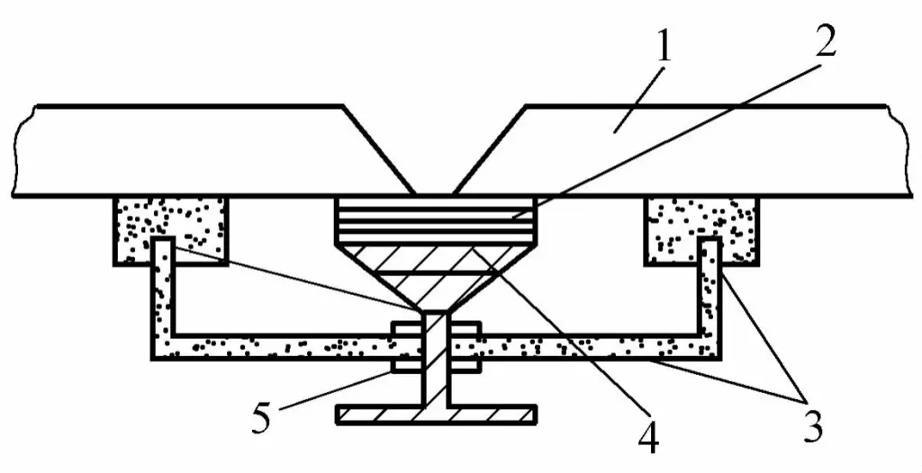
1—Workpiece
2—Thermosetting flux pad
3—Magnet
4—Support Plate
5—Adjustment Screw
When using this type of flux pad, workpieces generally have a V-shaped (with blunt edge) groove. To improve productivity, a certain height of ferroalloy powder can be stacked inside the groove. Since this process is minimally affected by the structure, position, and size of the workpiece, it has a broad application prospect. See Table 5-43 for the welding parameters of thermosetting flux pad submerged arc welding.
Table 5-43 Thermosetting Flux Pad Submerged Arc Welding Parameters
| Workpiece Thickness/mm | V-shaped Groove | Welding Sequence | Welding Current/A | Arc Voltage/V | Welding speed / (m/h) | Metal powder thickness / mm | |
| Angle(°) | Gap/mm | ||||||
| 9 | 50 | 0~4 | 1 | 720 | 34 | 18 | 9 |
| 12 | 50 | 0~4 | 1 | 800 | 34 | 18 | 12 |
| 16 | 50 | 0~4 | 1 | 900 | 34 | 15 | 16 |
| 20 | 50 | 0~4 | 1 | 850 | 34 | 15 | 15 |
| 2 | 820 | 36 | |||||
2) Single-sided welding with backing strip and lock joint.
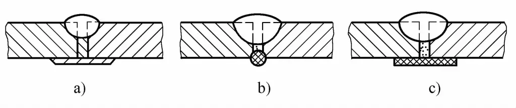
When the structure of the workpiece or the process equipment limits the implementation of single-sided welding with double-sided formation, single-sided welding with a backing strip or a lock joint can be used, as shown in Figure 5-46. The material of the backing strip should be the same as the workpiece. When assembling the backing strip, it should be tightly attached to the workpiece with a gap less than 1mm to prevent welding defects. See Table 5-44 for the welding parameters of single-sided submerged arc welding with a backing strip.
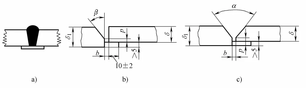
a) Single-sided welding with backing strip
b), c) Lock joint single-sided welding groove form
β =20°~ 40° b=2~5mm P=0~4mm α=20°~40° b=2~5mm P=2~5mm
Table 5-44 Welding parameters for single-sided submerged arc welding with backing strip
| Weldment thickness/mm | Assembly clearance/mm | Welding wire diameter/mm | Welding current/A | Welding voltage/V | Welding speed/(m/h) | Backing plate size/(mm×mm) |
| 2 | 0.7 | ф3 | 270~300 | 23~27 | 82 | 1×12 |
| 2.5 | 0.7 | ф3 | 270~300 | 23~27 | 75 | 1.5 x15 |
| 3 | 0.7 | ф3 | 270~300 | 23~27 | 60 | 1.5×15 |
| 4 | 0.7 | ф4 | 560~600 | 37~40 | 45 | 2×20 |
| 6 | 0.8 | ф4 | 680~720 | 35~37 | 45 | 3×25 |
Single-sided welding with a backing plate is commonly used for small diameter cylinders (such as LPG cylinders) and medium and low pressure pipeline circumferential seam welding.
3) Single-sided welding of other welding methods for root pass.
Refers to single-sided welding using shielded metal arc welding or gas shielded welding for the root pass, followed by submerged arc welding. Generally, the thickness of the root pass layer is required to be above 6mm to prevent burn-through during submerged arc welding.
1) Double-sided welding with flux backing.
Double-sided welding with flux backing is the most widely used method in submerged arc welding butt welding, suitable for medium and thick plate welding. Generally, the first side of the weld is backed on the flux pad, and when flipping to weld the other side, to ensure penetration, carbon arc gouging or other mechanical processing methods can be used to properly clean the root. See Table 5-45 for welding parameters of double-sided welding with flux backing.
Table 5-45 Welding parameters for double-sided welding with flux backing
| Workpiece thickness/mm | Joint form | Wire diameter/mm | Welding current/A | Arc voltage/V | Welding speed/(m/h) |
| 6 |  | 4 | 400 ~ 500 | 29 ~32 | 38~42 |
| 8 |  | 4 | 450 ~550 | 30 ~32 | 36 ~40 |
| 10 |  | 4 | 550 ~ 650 | 32~34 | 36 ~40 |
| 12 |  | 2 | 600 ~700 | 34~36 | 36 ~40 |
| 14 |  | 5 | 700 ~ 800 | 36 ~38 | 30~34 |
| 16 |  | 5 | 700 ~ 800 | 36~38 | 30~34 |
| 25 |  | 5 | 700 ~ 800 | 36~38 | 30~34 |
| >40 | 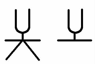 | 5 | 700 ~ 800 | 36~38 | 30 ~34 |
2) Temporary process backing plate method double-sided welding.
The function of the temporary process backing plate is to support the flux filled into the gap. When welding straight seams, the backing plate is a steel strip with a thickness of 3~4mm and a width of 30~50mm, or asbestos rope and board can also be used as supports. A certain gap must be left before welding the first side to ensure that the fine-grain flux can enter.
After welding the first side, flip the workpiece and remove the support, the flux in the gap, and the slag shell at the root of the weld, then proceed with the second side welding. See Table 5-45 for welding parameters for double-sided welding with flux pad method. Various forms of temporary process backing plates are shown in Figure 5-47.
a) Thin steel strip pad
b) Asbestos rope pad
c) Asbestos board pad
3) Suspension method double-sided welding.
When welding using the suspension method, no backing is added to the back of the workpiece, and no auxiliary equipment or devices are needed. To prevent the loss of molten metal through the gap or burn-through, strict control of the gap is required, and generally no gap is left or the gap is ≤1mm during assembly.
The welding parameters on the front side of the weld should be smaller, with a penetration depth less than half of the thickness of the workpiece; after flipping the workpiece, weld the back side, and to ensure penetration, appropriately increase the welding current to ensure the penetration depth reaches 60%~70% of the thickness of the workpiece. See Table 5-46 for the welding parameters of overhead double-sided welding.
Table 5-46 Overhead Double-Sided Welding Parameters
| Workpiece Thickness /mm | Wire Diameter /mm | Welding Sequence | Welding Current /A | Welding Voltage /V | Welding Speed /(m/h) |
| 6 | 4 | Direct | 300~420 | 30 | 34.6 |
| Reverse | 430 ~ 470 | 30 | 32. 7 | ||
| 8 | 4 | Direct | 440 ~480 | 30 | 30 |
| Reverse | 480 ~530 | 31 | 30 | ||
| 10 | 4 | Direct | 530~570 | 31 | 27.7 |
| Reverse | 590 ~ 640 | 33 | 27.7 | ||
| 12 | 4 | Direct | 620~660 | 35 | 25 |
| Reverse | 680~720 | 35 | 24.8 | ||
| 14 | 4 | Direct | 680~720 | 37 | 24.6 |
| Reverse | 730 ~ 770 | 40 | 22. 5 | ||
| 15 | 5 | Direct | 800 ~ 850 | 34~36 | 38 |
| Reverse | 850 ~ 900 | 36~38 | 26 | ||
| 17 | 5 | Direct | 850 ~ 900 | 35~37 | 36 |
| Reverse | 900 ~ 950 | 37~39 | 24 | ||
| 18 | 5 | Direct | 850 ~ 900 | 36~38 | 36 |
| Reverse | 900 ~ 950 | 38~40 | 24 | ||
| 20 | 5 | Direct | 850 ~ 900 | 36~38 | 35 |
| Reverse | 900 ~1000 | 38~40 | 24 | ||
| 22 | 5 | Direct | 900 ~ 950 | 37~39 | 32 |
| Reverse | 1000 ~1050 | 38~40 | 24 |
4) Thick plate butt welding.
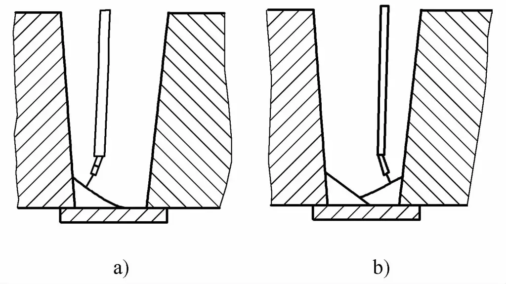
When the thickness of the workpiece is large, multi-layer welding is mostly used. The cross-section of the weld bead is only 70% of the general submerged arc welding method, and the edge weld bead must be tangent to the bevel for fusion, and appropriately form a concave smooth transition. When welding the cover surface, you can first weld the sides of the bevel, then weld the middle weld bead, or successively cover the surface in a banding pattern.
The groove form for thick plate butt welding. For weldments with a thickness of 22~36mm, V-shape (with blunt edge) or X-shape (with blunt edge) grooves are commonly used. For weldments with a thickness >38mm, it is advisable to use U-shape (with blunt edge), UV-shape (with blunt edge), or double U-shape (with blunt edge) grooves, as shown in Figure 5-48. It is best to use mechanical processing for the grooves.
Choose welding flux that is easy to remove slag and recover it in time during the welding process.
Use double pass multi-layer welding, with a swingable contact tip during single wire welding, having a certain swing angle (≤6°), the swing angle of the contact tip is shown in Figure 5-49; during twin wire welding, the front wire swings, and the rear wire is straight.
Welding parameters for thick plate deep groove are shown in Table 5-47.
Table 5-47 Thick plate deep groove welding parameters
| Wire diameter/mm | Welding current/A | Arc Voltage /V | Welding Speed /m/h | |
| AC | DC Reverse Polarity | |||
| 4 | 600 ~700 | 36~38 | 34~36 | 25~30 |
| 5 | 700 ~ 800 | 38~42 | 36~40 | 28 ~32 |
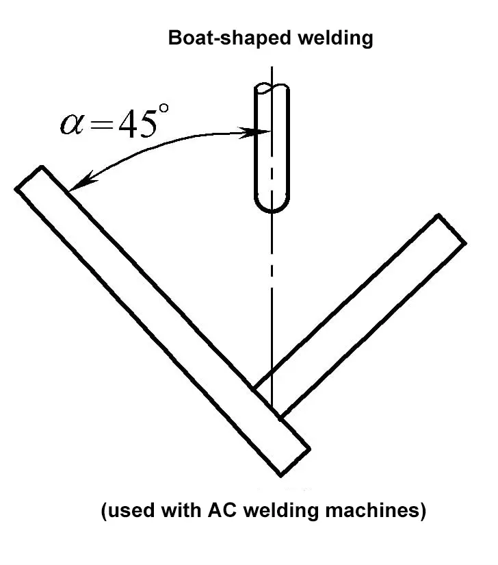
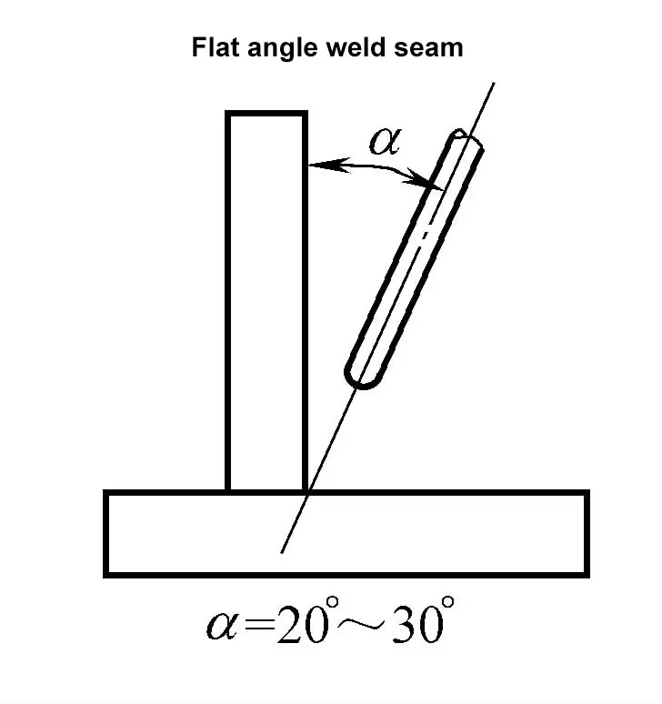
T-joints and lap joints form fillet welds. Boat-shaped welding and flat angle welding methods can be used, see Table 5-48 for reference welding parameters for submerged arc welding of fillet welds. During flat angle transverse welding, the maximum length of the weld toe ≤8mm, otherwise defects such as metal overflow and undercut will occur.
Table 5-48 Reference welding parameters for submerged arc welding of fillet welds
| Welding Method | Weld Toe Length/mm | Wire Diameter/mm | Welding Current/A | Arc Voltage/V | Welding Speed/(cm/min) | Note |
 | 6 | 2 | 450 ~ 475 | 34 ~36 | 67 | Assembly gap <1.5mm, otherwise measures must be taken to prevent the loss of molten metal |
| 8 | 3 | 550~600 | 34~36 | 50 | ||
| 4 | 575~625 | 34~36 | 50 | |||
| 10 | 3 | 600~650 | 34~36 | 38 | ||
| 4 | 650~700 | 34~36 | 38 | |||
| 12 | 3 | 600~650 | 34~36 | 25 | ||
| 4 | 725~775 | 36~38 | 33 | |||
| 5 | 775~825 | 36~38 | 30 | |||
 | 3 | 2 | 200 ~220 | 25~28 | 100 | DC Welder |
| 4 | 2 | 280~300 | 28~30 | 92 | Use fine-grain flux HJ431 with AC welder | |
| 3 | 350 | 28~30 | 92 | |||
| 5 | 2 | 375 ~ 400 | 30~32 | 92 | ||
| 3 | 450 | 28~30 | 92 | |||
| 4 | 450 | 28~30 | 100 | |||
| 7 | 2 | 375~400 | 30~32 | 47 | ||
| 3 | 500 | 30~32 | 80 | |||
| 4 | 675 | 32~35 | 83 |
1) Welding sequence:
Generally, weld the inner circumferential seam first, then the outer circumferential seam, with an overlap of 30mm at the start and end points of the weld.
2) Selection of Offset:
During automatic circumferential seam welding, the welding wire should have an offset relative to the center of the workpiece opposite to the rotation direction of the workpiece, as shown in Figure 5-50, to ensure good weld formation. The optimal value of offset a should also be adjusted according to the quality of the weld formation. The selection of welding wire offset is shown in Table 5-49.
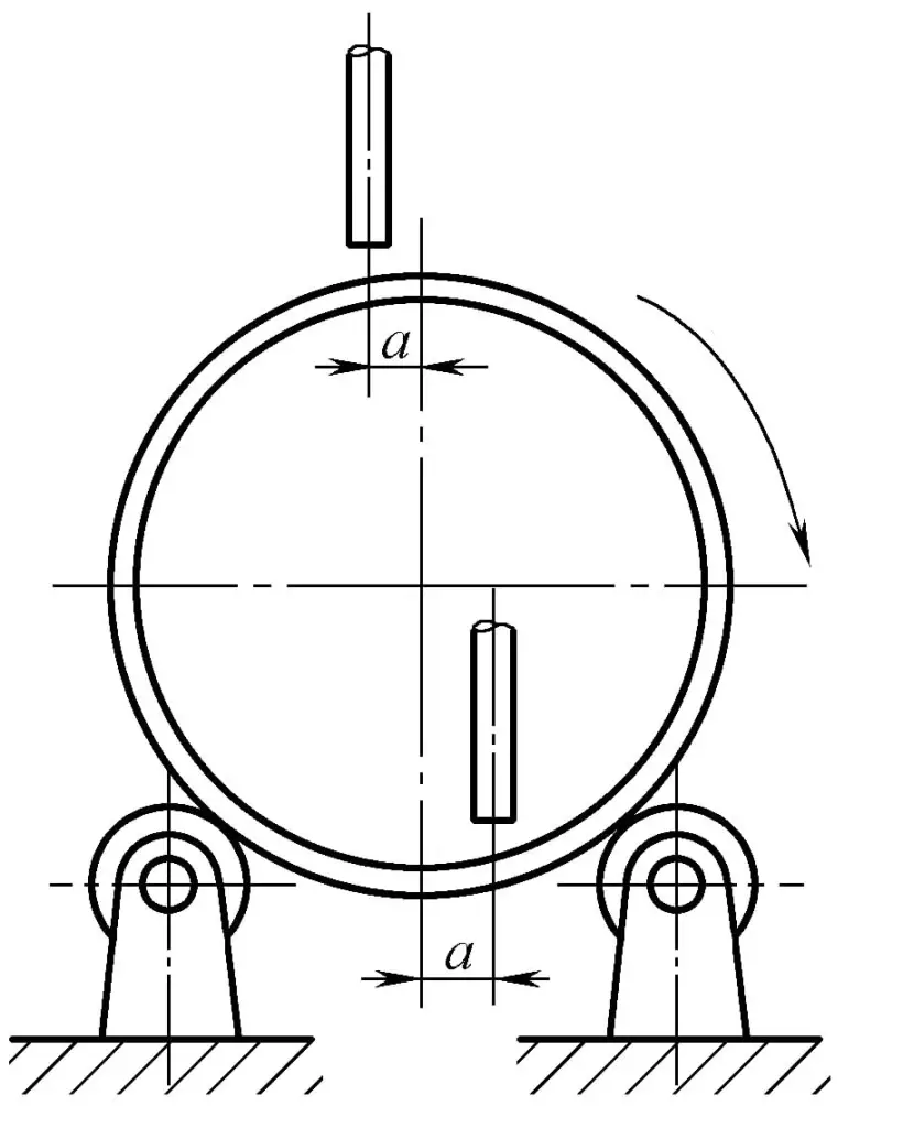
Table 5-49 Selection of Welding Wire Offset
| Cylinder Diameter/mm | Offset a/mm |
| 800~1000 | 20 ~25 |
| <1500 | 30 |
| <2000 | 35 |
| <3000 | 40 |