Bending Component Manufacturing: A Detailed Guide
Imagine transforming a flat, unremarkable sheet of metal into a precisely curved, structurally essential component. This magic of material manipulation…
Imagine taking a flat sheet of metal and transforming it into a precise, curved structure essential for rail passenger cars. This blog dives into the various techniques of bend manufacturing, exploring methods like folding, die bending, and roll bending. You’ll learn about the materials involved, from carbon steel to aluminum alloys, and discover how different bending processes affect the final product’s quality and efficiency. By the end, you’ll understand the critical role of these techniques in manufacturing robust, reliable components for modern rail vehicles.
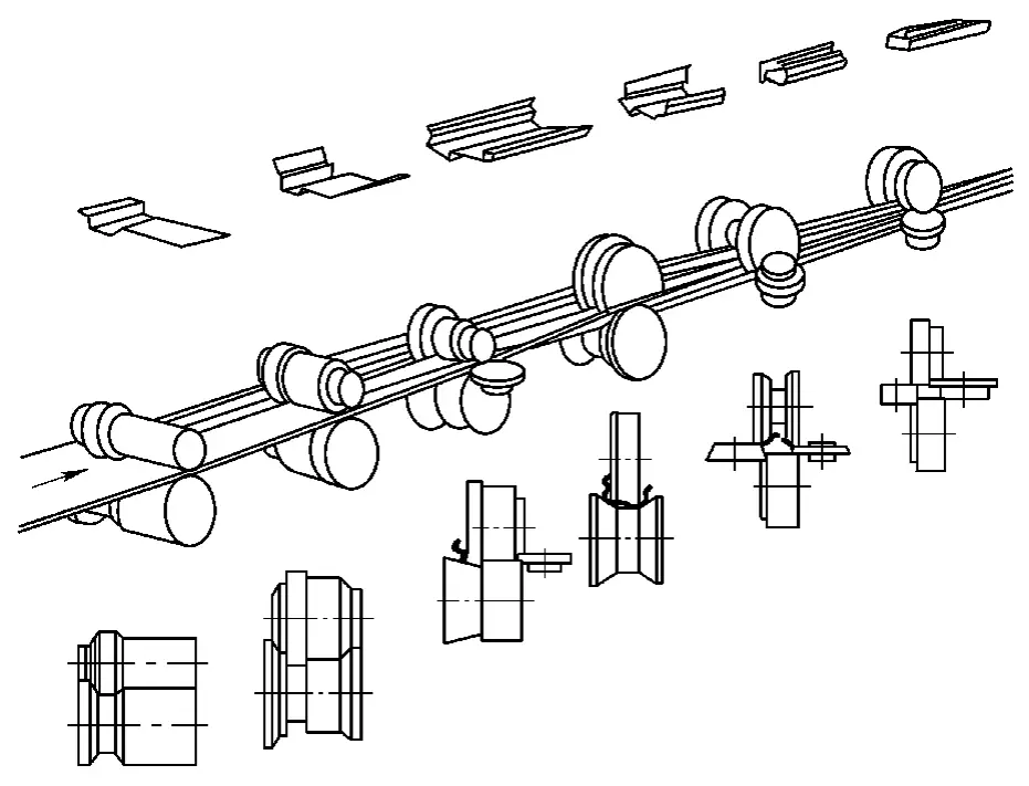
Bending is a forming method where metal sheets and profiles are shaped into a certain curvature or angle under the influence of a die. Bending can be performed on a general press machine or on a specialized machine.
There are many types of bend parts used in rail passenger cars, with the main types listed in Table 3-83.
Table 3-83: Types of Bend Parts in Rail Passenger Cars
| Serial Number | Type | Part Shape, Name | Equipment Used |
| 1 | Folded Parts | 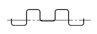 Outer Panel Reinforcement Beam 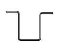 Pillar | CNC Bending Machine |
| 2 | Die Pressed Parts | 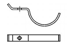 Pipe Clamp 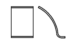 Plate | Press Machine |
 Bogie Side Beam Lower Cover Plate | Hydraulic Machine | ||
| 3 | Roll-Bent Component | 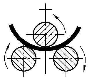 Roof Panel in Passenger Cars | Plate Rolling Machine |
 Aluminum Profile Bent Beam | Profile Rolling Machine | ||
| 4 | Draw-Bent Component | 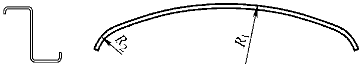 Roof Bent Beam | Profile Bending Machine |
| 5 | Cold-Bent Component | 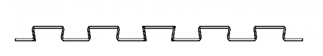 Stainless Steel Corrugated Floor 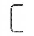 Side Beam | Cold Bending Forming Production Line |
The primary materials for bent components in rail passenger cars include the following:
The main bending methods for rail passenger car bent components include the following:
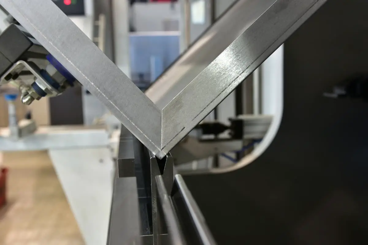
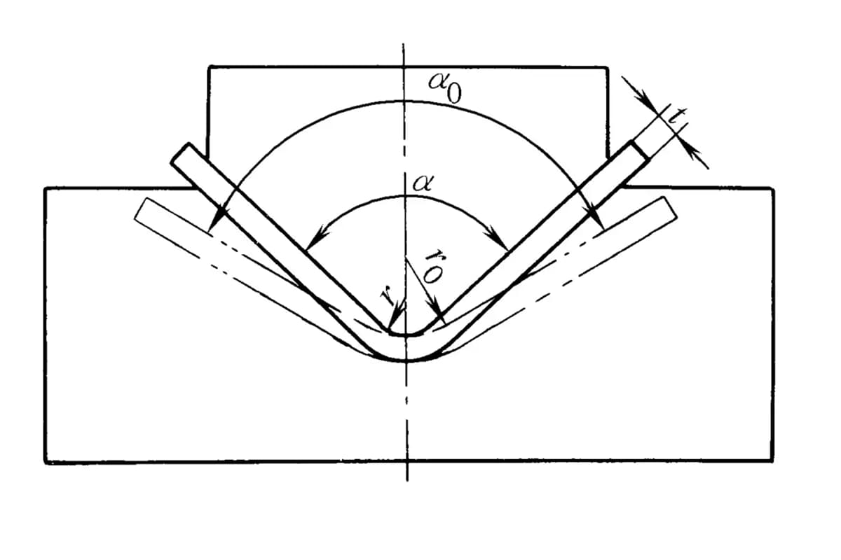
This process involves using a folding machine and its dies to perform straight line bending on sheet metal. The characteristic of this method is the use of general-purpose dies, forming one bend per stroke, with the bending angle accurately controlled by the stroke, as shown in Figure 3-89.
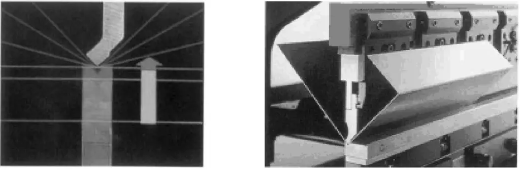
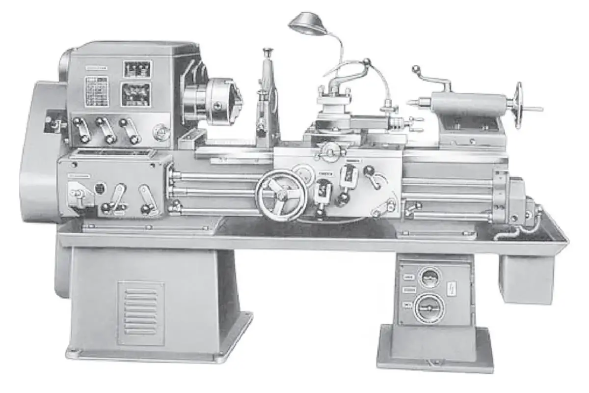
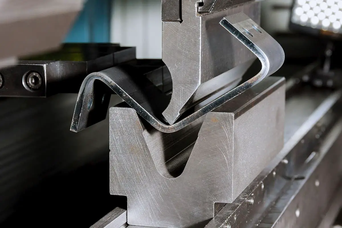
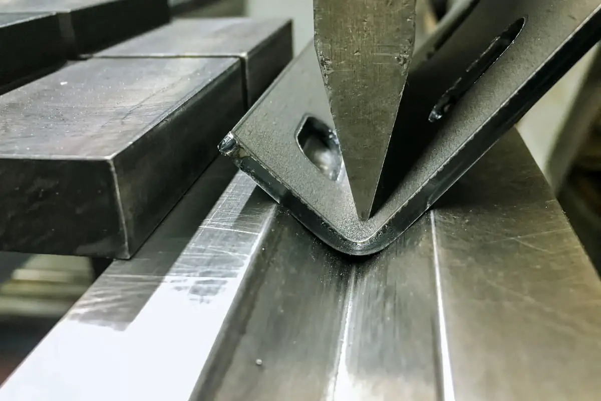
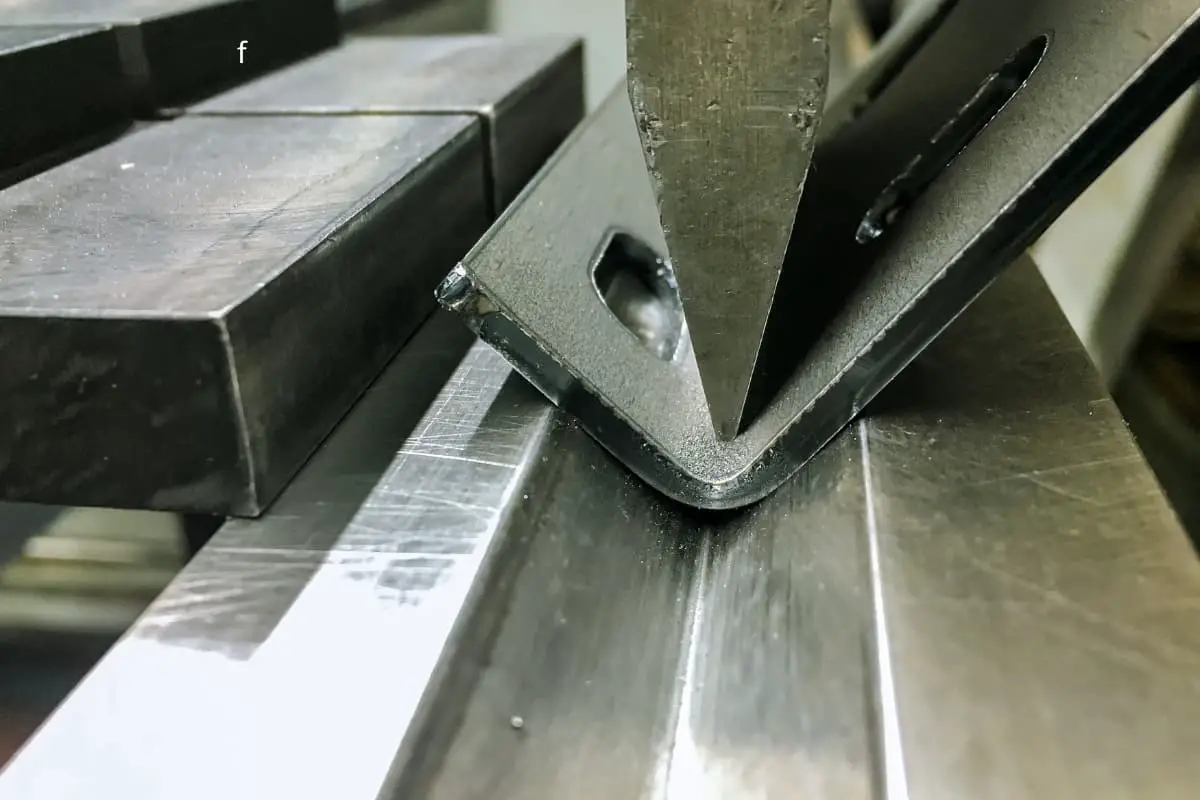
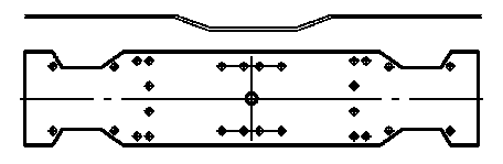
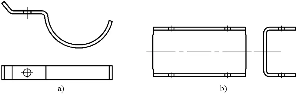
The most common bending method, which uses a press machine and dies to perform any form of bending on the sheet metal, as shown in Figure 3-90.
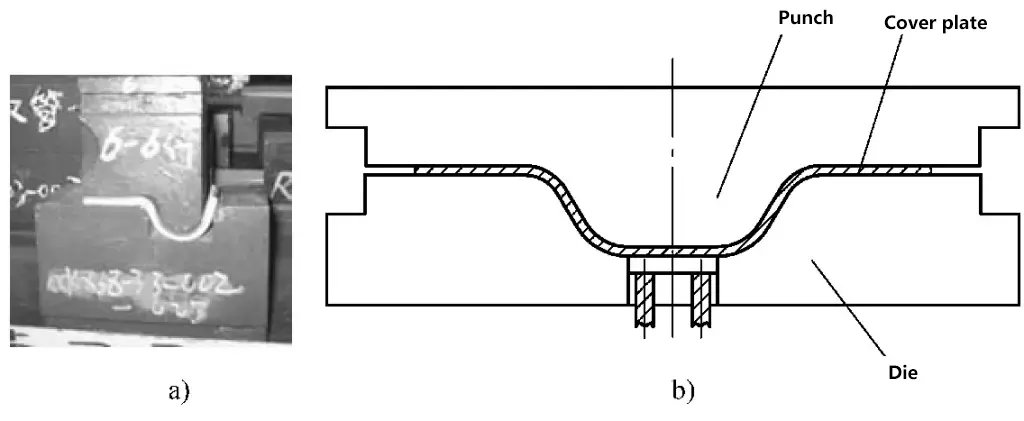
a) Tube Clamp Bending
b) Cover Plate Bending
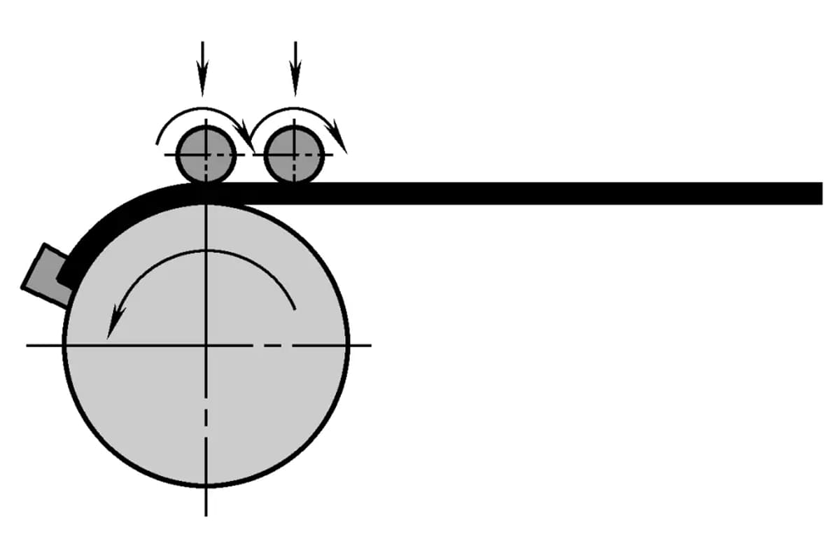
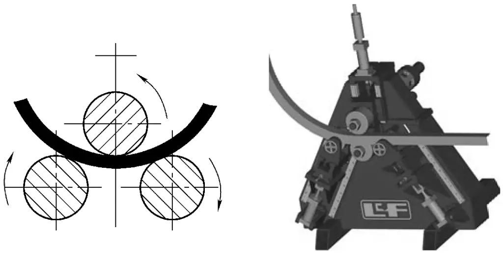
Roll bending refers to the process of shaping blanks of sheet metal and profiles on a roll bending machine, as shown in Figure 3-91.
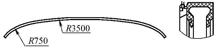
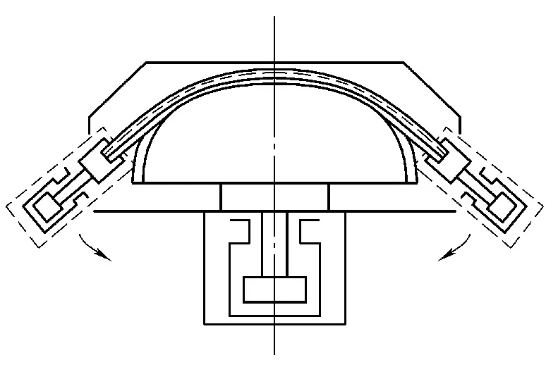
Draw bending involves shaping a certain profile of extruded and bent sheet metal on a draw bending machine mold, applying axial tensile force and bending moment simultaneously.
This process changes the internal stress conditions of the blank, making the cross-section under tensile stress, which helps avoid wrinkling defects, increases the amount of plastic deformation, reduces springback, and enhances bending forming accuracy, as depicted in Figure 3-92.
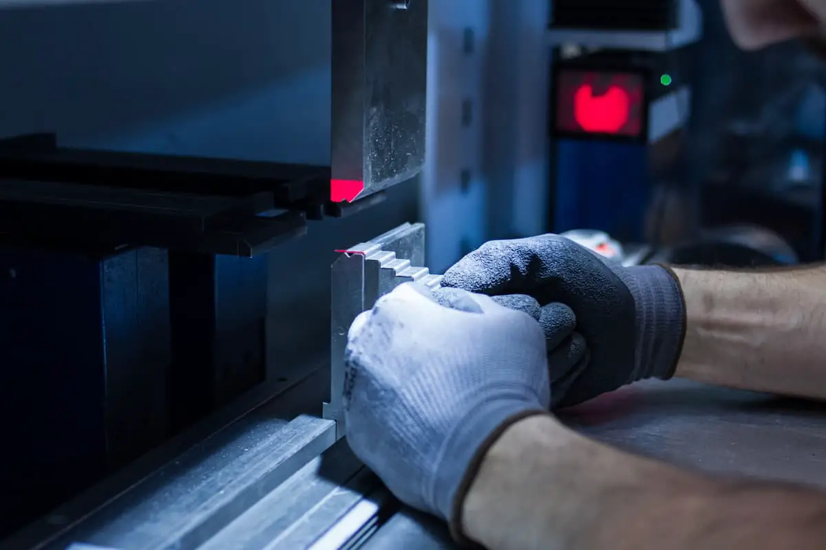
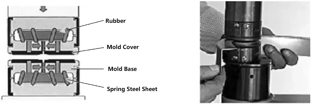
Peen forming is a process where a toothed die on a peening hammer, capable of inward and outward movements, causes the material to stretch and contract, gradually inducing bending and tensile deformation in the workpiece (Figure 3-93).
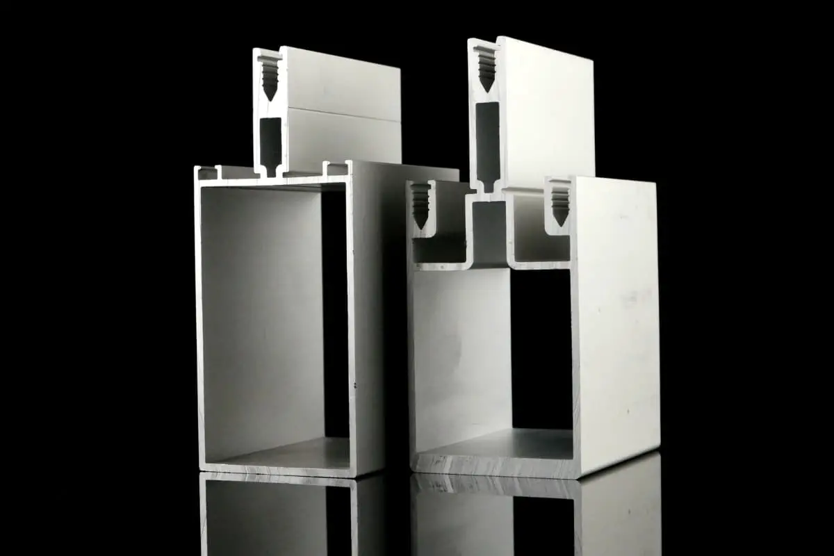
Cold forming involves using multiple longitudinally arranged forming rolls to continuously bend metal sheets such as coil or strip into specific sectional profiles.
Cold forming is a material-saving, energy-efficient, and highly productive new metal forming process and technology, as shown in Figure 3-94.
There are six commonly used bending methods for stamped parts in rail vehicles. The choice is made based on the shape of the part, material, batch size, equipment conditions, and quality requirements while also considering cost-effectiveness.
Bend forming is the first choice because it generally uses universal molds that are simple and easy to prepare. Equipping the bending machine with the appropriate mold allows the formation of thick plate cover parts that previously required large molds.
For various small cross-sectional bend profiles, hot-rolled steel, and aluminum alloy extruded profiles with large curvature radii, draw bending is chosen.
For high-volume small bent parts, die forming is the preferred method, such as for tube clamp parts and small channel iron (Figure 3-95).
a) Tube clamp
b) Small channel iron
Angle profiles are preferably formed by hammering, followed by roll bending or draw bending.
For workpieces longer than 4m and with complex cross-sectional shapes, cold bending is chosen.
For large cover plate forming, the method is selected based on production quantity. Mold forming is chosen for large batches, while bending forming is chosen for smaller ones.
Springback refers to the elastic deformation of the material after the stamped part is bent, causing changes in the angle and fillet radius of the workpiece (Figure 3-96).
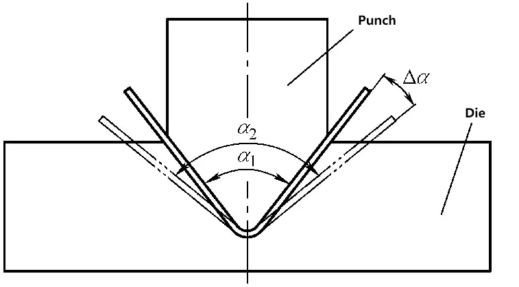
α1) the angle of the punch
α2) the angle of the bent part after unloading
2Δa)the amount of springback.
1) The higher the yield strength of the material and the larger the elastic modulus, the greater the springback.
2) The smaller the relative bending radius R/t of the bent part, the less the springback.
3) The larger the opening of the V-shaped mold, the greater the springback. The deeper the concave mold of the U-shaped part, the less the springback.
4) The smaller the mold clearance, the less the springback.
5) Corrected bending has less springback than free bending, and the greater the correction force, the less the springback.
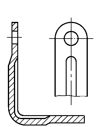
1)Improve the design of the bent part, reduce r/t as much as possible within the allowable range of material properties and structure, or suppress reinforcements in the bending area to increase the stiffness of the part and suppress springback (Figure 3-97).
2)Bending is performed using the folding method.
3)The draw bending method is employed for profiles with high curvature.
4)For die bending, corrective bending is used instead of free bending (Figure 3-98).
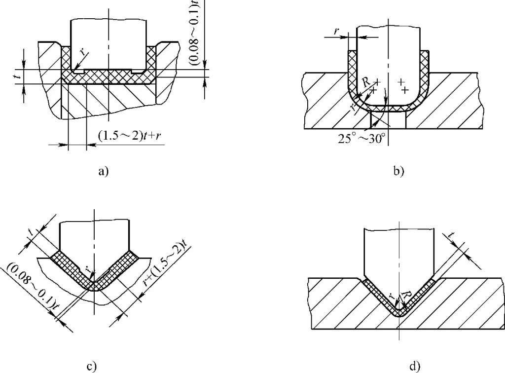
5)Select a reasonable bending die structure for springback compensation (Figure 3-99).
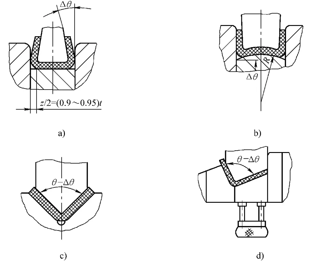
a) Small gap compensation
b) Concave compensation at the bottom of the punch
c) V-die single angle bending compensation
d) V-die single angle bending compensation
Bending cracks are one form of failure in bent parts. The primary cause of bending cracks is a bending radius that is too small relative to the material, exceeding the amount of deformation the material can withstand.
The minimum bending radius (rmin) refers to the smallest inner corner radius that a part can be bent into without causing damage to the sheet metal.
The commonly used relative minimum bending radius (rmin/t) represents the forming limit during bending. The smaller this value, the more conducive it is to bending and forming.
1)It is mainly related to the elongation rate of the material. The larger the elongation rate, the smaller the minimum bending radius.
2)The higher the surface smoothness and cross-sectional smoothness of the sheet metal, the smaller the minimum bending radius.
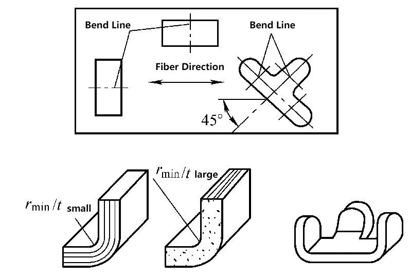
3)The minimum bending radius of a bend line perpendicular to the fiber direction is smaller than that parallel to the fiber direction (Figure 3-100).
1) Materials that have undergone cold deformation hardening can be heat-treated before bending.
2) Remove burrs at both ends of the bending line to improve smoothness.
3) For materials with low plasticity or thick materials, heating can be used for bending.
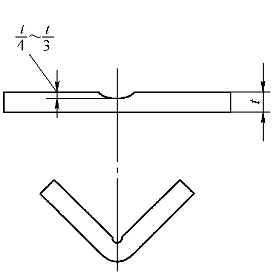
4) For bending of thicker materials, if the structure allows, a process groove can be made before bending (Figure 3-101).
The principle for calculating the size of the bent blank is to measure the length of the neutral layer. The specific method involves dividing the part into straight and curved arc sections, calculating the lengths separately, and then adding them together, as shown in Figure 3-102.

a) Part
b) Part Segmentation
Spread Length of the Part:
L = a1 + a2 + a3 + l1 + l2 + l3 + l4
The spread length of the arc part according to the neutral layer:
l = παρ/180 = 0.01745αρ
Where:
The formula for calculating the radius of the neutral layer (Figure 3-103):
ρ = r + xt
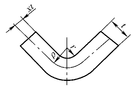
Where:
Table 3-84: Position Coefficient of the Neutral Layer
| r/t | Fraction | (1) | 3/10 | 5/16 | 8/25 | 1/3 | 12/35 | 5/14 | 3/8 | 2/5 | 5/12 | 3/7 | — |
| Decimal | (2) | 0.3 | 0.3125 | 0.32 | 0.333 | 0.343 | 0.357 | 0.375 | 0.4 | 0.417 | 0.429 | — | |
| x | (3) | 0.194 | 0.199 | 0.201 | 0.206 | 0.209 | 0.213 | 0.219 | 0.226 | 0.230 | 0.233 | — | |
| r/t | Fraction | (1) | 4/9 | 12/25 | 1/2 | 8/15 | 5/9 | 4/7 | 3/5 | 5/8 | 2/3 | 7/10 | 5/7 |
| Decimal | (2) | 0.444 | 0.48 | 0.5 | 0.533 | 0.555 | 0.571 | 0.6 | 0.625 | 0.667 | 0.7 | 0.714 | |
| x | (3) | 0.237 | 0.245 | 0.25 | 0.257 | 0.261 | 0.264 | 0.270 | 0.274 | 0.281 | 0.286 | 0.288 | |
| r/t | Fraction | (1) | 3/4 | 4/5 | 5/6 | 6/7 | 8/9 | 1 | 10/9 | 8/7 | 6/6 | 5/4 | 4/3 |
| Decimal | (2) | 0.75 | 0.8 | 0.833 | 0.857 | 0.889 | 1 | 1.111 | 1.143 | 1.2 | 1.25 | 1.333 | |
| x | (3) | 0.294 | 0.301 | 0.305 | 0.308 | 0.312 | 0.325 | 0.336 | 0.340 | 0.345 | 0.345 | 0.356 | |
| r/t | Fraction | (1) | 7/5 | 10/7 | 3/2 | 8/5 | 5/3 | 12/7 | 16/9 | 15/8 | 2 | 25/12 | 15/7 |
| Decimal | (2) | 1.4 | 1.429 | 1.5 | 1.6 | 1.667 | 1.714 | 1.778 | 1.875 | 2 | 2.083 | 2.143 | |
| x | (3) | 0.362 | 0.364 | 0.369 | 0.376 | 0.38 | 0.384 | 0.387 | 0.393 | 0.400 | 0.405 | 0.408 | |
| r/t | Fraction | (1) | 20/9 | 16/7 | 12/5 | 5/2 | 8/3 | 20/7 | 3 | 25/8 | 16/5 | 10/3 | 24/7 |
| Decimal | (2) | 2.222 | 2.286 | 2.4 | 2.5 | 2.667 | 2.857 | 3 | 3.125 | 3.2 | 3.333 | 3.429 | |
| x | (3) | 0.412 | 0.415 | 0.420 | 0.424 | 0.341 | 0.439 | 0.444 | 0.449 | 0.451 | 0.456 | 0.459 | |
| r/t | Fraction | (1) | 7/2 | 25/7 | 15/4 | 4 | 25/6 | 30/7 | 35/8 | 40/9 | 9/2 | 25/5 | 5 |
| Decimal | (2) | 3.5 | 3.571 | 3.75 | 4 | 4.167 | 4.286 | 4.375 | 4.444 | 4.5 | 4.8 | 5 | |
| x | (3) | 0.461 | 0.463 | 0.469 | 0.476 | 0.480 | 0.483 | 0.485 | 0.487 | 0.488 | 0.495 | 0.500 | |
Typically, the spread length of the bent part is calculated using the above method. However, due to differences in material properties, varying bending angles, and plate thickness tolerances, there may be some errors.
Therefore, for workpieces with high precision requirements, experimental verification should be carried out, and adjustments should be made as appropriate.
(1) Bending Force During Air Bending
Bending force for V-shaped parts:
Fa=0.6KBt2Rm/(r+t)
Bending force for U-shaped parts:
Fa=0.7KBt2Rm/(r+t)
Where,
(2) Bending Force During Correction Bending
Fcorr = Ap
Where,
Table 3-85: Unit Correction Force, p(Unit: MPa)
| Material | Material Thickness | |||
| ≤1 | >1~2 | >2~5 | >5~10 | |
| Aluminum | 10~15 | 15~20 | 20~30 | 30~40 |
| Brass | 15~20 | 20~30 | 30~40 | 40~50 |
| 10~20 Steel | 20~30 | 30~40 | 40~50 | 50~70 |
| 25~35 Steel | 30~40 | 40~50 | 50~70 | 70~100 |
(3) The punch force or blank holder force, if the bending die is equipped with a punch device or a blank holder device, can be approximated as 30% to 80% of the free bending force. That is,
FY =(0.3~0.8)Fa
(4) Determination of Press Tonnage for Free Bending with a Blank Holder
Fpress ≥ (1.2~1.3) (Fa + FY)
For Correction Bending
Fpress ≥ (1.2~1.3) Fcorr