Metal Joining: Welding, Riveting, and Threading Explained
How do we build the machines that power our world? Dive into the art of mechanical joining, where metal meets…
Imagine crafting perfect welds with pinpoint precision, no matter the material. Welcome to the world of TIG welding, a technique prized for its versatility and high-quality results. This guide delves into the principles, advantages, and applications of TIG welding, offering insights into its superior control and finish. From understanding the role of argon gas to mastering the use of non-consumable tungsten electrodes, this article equips you with the knowledge to elevate your welding skills. Discover how TIG welding can transform your projects with cleaner, stronger, and more aesthetically pleasing welds.
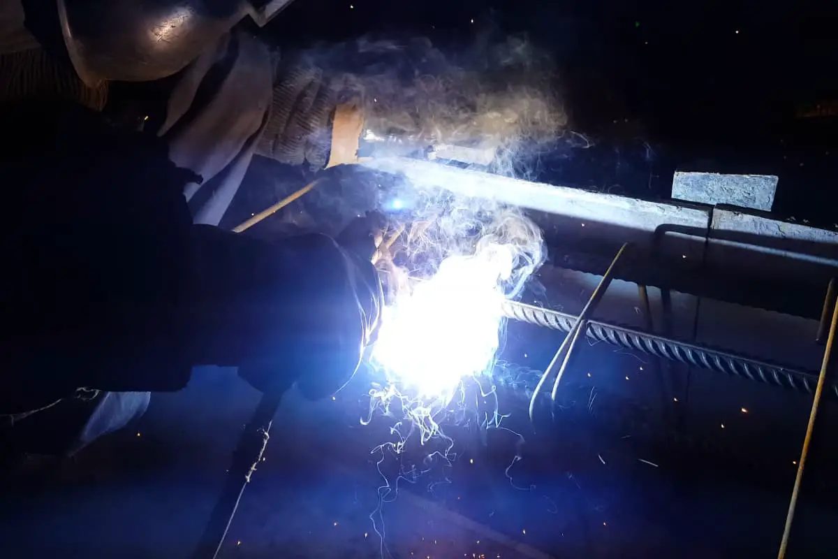
Tungsten Inert Gas (TIG) welding, often referred to as TIG welding, is a type of arc welding that generates heat between a non-consumable electrode and the workpiece.
The electrode rod, weld pool, arc, and the vicinity of the heated area of the workpiece are all isolated from atmospheric contamination by a gas shield. This shield is supplied by a steady flow of gas or gas mixture, typically an inert gas, which must provide complete protection as even a small amount of air contamination can spoil the weld bead.
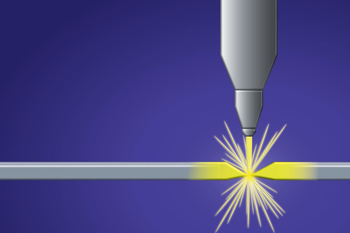
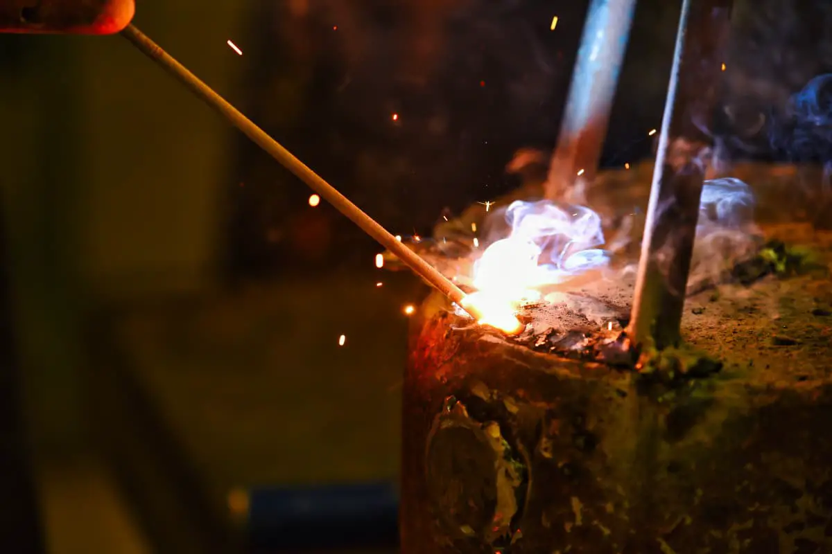
A method of arc welding that uses refractory metal pure tungsten or activated tungsten (thoriated tungsten, ceriated tungsten) as the electrode, with argon gas to protect the electrode, arc zone, and molten metal, commonly known as tungsten inert gas (TIG) welding, is illustrated in Figure 5-53.
Argon is an inert gas and does not dissolve in liquid metal. During welding, the arc burns between the electrode and the workpiece, and argon gas isolates the metal pool, molten droplets, and tungsten electrode tip from the air.
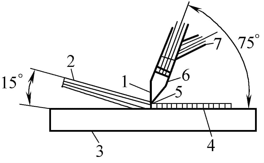
1—Tungsten Electrode 2—Filler Metal 3—Workpiece 4—Weld Metal 5—Arc 6—Nozzle 7—Shielding Gas
1) The electrode made of refractory metal tungsten or activated tungsten does not melt during welding. Using argon gas to isolate the atmosphere prevents the effects of gases like oxygen, nitrogen, and hydrogen on the arc and molten pool, and the elements of the welded metal and welding wire are not easily burnt off (only a very few are burnt off).
Therefore, it is easy to maintain a constant arc length, the welding process is stable, and the welding quality is good.
2) During welding, flux is not required, and there is no slag on the weld surface, which facilitates observation of the molten pool and weld formation, and defects can be promptly detected. Appropriate measures can be taken during the welding process to eliminate defects.
3) Tungsten inert gas welding has good stability, and the arc can still burn stably when the welding current is less than 10A. Therefore, it is particularly suitable for welding thin plates.
Since the heat source and filler wire are controlled separately, heat adjustment is convenient, making it easier to control the heat input to the weld. Thus, it is suitable for welding in various positions and also facilitates single-sided welding with double-sided formation.
4) The flow of argon gas compresses the arc, thus the heat is more concentrated, and the molten pool is smaller; due to the cooling effect of argon gas near the seam area, the heat-affected zone is narrowed, reducing the deformation of the workpiece.
The weld joint structure is compact, and the overall mechanical properties are better; when welding stainless steel, the corrosion resistance of the weld, especially its resistance to intergranular corrosion, is particularly good.
5) Since the filler wire does not carry the welding current, it does not produce spatter caused by changes in arc voltage and current due to molten droplet transition, providing good conditions for obtaining a smooth weld surface.
The arc in tungsten inert gas welding is a bright arc, the welding process parameters are stable, easy to monitor and control, and conducive to mechanized and automated welding.
1) Tungsten inert gas welding uses gas for protection and has poor resistance to lateral wind. The penetration is shallow, the deposition speed is low, and the productivity is low.
There is a small amount of tungsten evaporation, and tungsten particles entering the weld pool can cause tungsten inclusion, affecting the weld quality, especially when the current is too high, tungsten electrode burn-off is severe, and tungsten inclusion is obvious.
2) Compared to shielded metal arc welding, it is more difficult to operate, the equipment is more complex, and the cleaning requirements for the weldments are particularly high. The production cost is higher than that of shielded metal arc welding, submerged arc welding, and CO2 welding.
Tungsten inert gas welding can weld oxidizable non-ferrous metals and their alloys, stainless steel, high-temperature alloys, titanium and titanium alloys, as well as refractory active metals (molybdenum, niobium, zirconium), etc., mainly for welding thin plates with a thickness of less than 3mm.
For important structures with large thickness, such as pressure vessels and pipelines, it can be used for root pass welding. Tungsten inert gas weldin
Tungsten Inert Gas (TIG) welding, whether manually or automatically performed, is suitable for continuous welding, intermittent welding (sometimes referred to as “skip welding”), and spot welding. Given that its electrode is non-consumable, welding can be performed by simply melting the base metal without needing to add filler metal. However, for certain joints, filler metal may be required based on specific needs.
TIG welding is a versatile welding method that is especially suitable for welding thin sheets, often as thin as 0.005 inches.
The characteristics of TIG welding allow it to be used for welding most metals and alloys. Metals that can be welded with TIG include carbon steel, alloy steel, stainless steel, heat-resistant alloys, refractory metals, aluminum alloys, magnesium alloys, beryllium alloys, copper alloys, nickel alloys, titanium alloys, and zirconium alloys, among others.
Lead and zinc are difficult to weld with TIG. The low melting points of these metals make controlling the welding process extremely challenging. Zinc vaporizes at 1663°F, a temperature still considerably lower than the arc temperature, and the vaporization of zinc can deteriorate the weld bead. Steel surfaces coated with lead, tin, zinc, cadmium, or aluminum and other metals that melt at higher temperatures can be arc welded, but require special procedures.
In welded joints of coated metals, the mechanical properties may be reduced due to the formation of “intermetallic compounds.” To prevent intermetallic formation during the welding of coated metals, the surface coating in the area to be welded must be removed, and then repaired after welding.
TIG welding can be applied to a wide range of metal thicknesses. It is particularly suitable for welding objects less than 3mm thick because the arc generates a high concentration of heat, resulting in high welding speeds. Multiple weld passes can be made with the use of filler metal.
Though other welding methods are typically used for base metals thicker than 6.25mm, high-quality, thick weldments may require TIG welding for multi-pass welding. For example, in the manufacture of a 15mm-thick shell for an 8m-diameter rocket engine, TIG welding with filler metal is used for multiple longitudinal and circumferential welds. Although this method is slower for such thick metals, TIG welding is used due to the high-quality requirements of the weld bead.
TIG welding can successfully weld various “foil thickness” alloys. Thin sheet welding requires precise equipment fixation. For foil-thickness metals, mechanical or automatic welding is needed. “High-Temperature Ion Arc Welding” is often recognized as a variation of TIG welding, offering more advantages for thin sheet welding.
Manual welding is required for complex shapes when using automatic methods. Manual operation is suitable for irregularly shaped objects needing short weld beads, or for welding in hard-to-reach areas. Manual operation is also suitable for all-position welding.
Automatic equipment can weld curved and straight surfaces. For example, a special sinusoidal welding method is used for the two ends of a wave-shaped titanium electrode against the components. For this type of sinusoidal welding, a mechanical guiding unit follows a metal template to guide the welding torch. Manual operation of such welding presents extreme control challenges.
In Tungsten Inert Gas (TIG) welding, heat is generated between the electrode and the workpiece, melting the edges of the latter. It is crucial to keep the weld pool clean upon solidification for proper fusion. To achieve high-quality welds with TIG, all surfaces and adjacent areas to be welded must be thoroughly cleaned, as well as any filler metal used.
Another fundamental requirement is the accurate and steady positioning of the components to be welded, particularly when high precision is required, and the workpiece is thin and complexly shaped. Special fixtures may be needed when welding without filler metal or during automated welding.
1. Arc Initiation
The common methods for “arc initiation” involve triggering electron emission and gas ionization. This can be achieved by quickly retracting the energized electrode from the workpiece to the required arc length, or using a pilot arc, or an auxiliary device that generates a high-frequency spark between the electrode and the workpiece.
The mechanical retraction of the electrode from the workpiece can only be used for mechanized welding with DC welding machines. However, the pilot arc initiation method can be used for manual and mechanized welding, but is also limited to DC welding machines. The high-frequency spark initiation method can be applied to manual welding with either AC or DC welding machines. Many welding machines have devices to generate high-frequency sparks for arc initiation and stabilization.
2. Electrode Rod and Filler Metal Positioning
In manual tungsten arc welding, once the arc is initiated, maintain the welding torch so that the electrode rod is about 75º away from the surface of the workpiece, pointing towards the welding direction. At the start of welding, the arc normally moves in a circular manner until enough base metal has melted to produce a molten pool of appropriate size.
When the adequate fusion is achieved, gradually move the welding torch along the adjacent edges of the workpiece joint. This gradual fusion of the workpiece is typically done while the filler metal, when manually added, is kept at about a 15º angle from the surface of the workpiece, slowly entering the molten pool.
Care must be taken to feed the filler metal to avoid disrupting the gas shield or touching the electrode rod and causing contamination from the oxidation of the filler rod end or the electrode rod. The filler metal rod can be continuously added or repeatedly “dipped in” and “pulled out”.
Filler metal can be continuously added by maintaining a linear arrangement between the filler rod and the weld path (often used in multi-pass joints with a V-shaped joint), or by swinging the filler rod and welding torch left and right to feed the filler rod into the molten pool (commonly used in a surfacing process).
When stopping welding, pull the filler metal from the molten pool but temporarily keep it under gas protection to prevent oxidation of the filler metal. Then, before extinguishing the arc, move the welding torch to the front edge of the molten pool, lifting the welding torch to just the right height to extinguish the arc but not enough to cause cratering and electrode rod contamination. The best practice is to gradually reduce the current using a foot pedal control method without needing to lift the welding torch.
3. Arc Length
In many fully automatic tungsten arc welding applications, the arc length used is approximately 1.5 times the diameter of the electrode rod, but it can vary depending on the specific application or the welder’s preference.
However, the longer the arc length, the higher the heat diffused into the surrounding atmosphere, and the long arc can often hinder (to some extent) the stable progress of welding. An exception is the “socket joint” in the pipeline; in vertical welding with the official axis, a long arc can produce a smoother fillet weld than a short arc.
4. Manual and Automatic Operations
A distinction exists between manual and fully automated tungsten inert gas (TIG) welding: manual welding is performed by “welders,” while automated welding is carried out by “operators.” For instance, manual control of welding current and switching via foot pedal are early developments leaning towards automation.
The use of a device that drives the welding gun at a fixed or planned speed, automatically adjusts the arc voltage (arc length), and automatically starts and stops, constitutes fully automated welding.
5. Welding Techniques
The selection and training of operators mainly depend on the “degree of automation” of the equipment used. Because TIG welding is often used for joining metal sheet parts, and in its application, welders can easily handle relatively small components.
Therefore, welders often spend part of their time cleaning, combining and fixing devices, and spot welding operations. Besides requiring high manual dexterity and patient training to achieve good quality weld beads, sometimes mechanical techniques are also essential for the proper assembly and fixing of components to be welded.
The need for specific welding techniques will change when transitioning from one welding method to another. For instance, a welder adept at manual gas shielded welding would require additional training to qualify for TIG welding. Moreover, some applications require specialized techniques, such as the placement and welding of consumable backing rings, and repair welding.
6. Inspection
Inspection of TIG welding includes all non-destructive methods, from surface inspection of sheet metal welds to radiographic (X-ray) and ultrasonic inspection of thicker weldments, to check for potential defects beneath the surface (internal).
In any welding operation, “current” is the most critical operational condition, as it is related to penetration depth, welding speed, solidification speed, and quality of the weld bead.
Basically, there are three types of welding current to choose from: (a) Direct Current Electrode Positive (DCEP), (b) Direct Current Electrode Negative (DCEN), (c) Alternating Current (AC). Some desired effects can be achieved by superimposing high-frequency current on these three types of current.
1. Direct Current Electrode Positive (DCEP)
DCEP is the most widely used current type for TIG welding and can produce good weld beads in almost all generally weldable metals and alloys.
In DCEP welding, the electrode rod is negative, and the workpiece metal is positive, so the electron flow is from the electrode rod to the workpiece metal. Since 70% of the heat in all DC arcs is generated at the positive or anode end of the arc, a given size electrode rod can withstand more positive current and less negative current.
Similarly, if a specific sized electrode rod needs the hottest arc, DCEP is the required current type.
DCEP can generate deep, narrow weld beads, and its “penetration” is superior to the other two types of current. However, the narrow weld bead and deeper penetration make DCEP welding thin metal objects difficult. Unlike DCEN or AC, DCEP cannot remove surface oxides from aluminum, magnesium, or beryllium copper.
But if aluminum is welded with DCEP, a specially modified welding method must be used, along with mechanical or chemical cleaning before welding. DCEP welding requires more skill compared to high-frequency stabilized AC arc welding, primarily because DCEP does not have high-frequency guiding discharge when striking the arc.
Therefore, a special device can be added to the standard machine to superimpose a high-frequency current on DCEP.
2. Direct Current Reverse Polarity
In Direct Current Reverse Polarity (DCRP) welding, the electrode rod is connected to the positive terminal of the welding machine, while the workpiece metal is connected to the negative terminal. As a result, the electron flow moves from the workpiece to the electrode rod.
This process generates higher heat in the electrode rod and lower heat in the workpiece. Given the same amperage and arc length, the voltage of DCRP arc is slightly higher than that of DCSP arc, resulting in a larger total energy for the DCRP arc.
DCRP is the least commonly used among the three types of electric currents due to its tendency to produce flat, wide, and shallow weld paths. Welding with DCRP requires advanced skills, as it necessitates the use of larger electrode rods for the same low welding current values. Thus, it is generally not used. DCRP provides the “coolest” effective arc but possesses superior characteristics in removing oxides from the workpiece surface.
Welding aluminum with DCRP is particularly challenging, as the molten pool is easily drawn towards the tip of the electrode rod. The electrode becomes contaminated upon contact with aluminum.
However, DCRP can be effectively used for joining thin aluminum sheets (0.6mm). On the other hand, magnesium, which is unaffected by DCRP’s inherent arc action and thus doesn’t encounter contamination issues, can be welded using DCRP for thicknesses up to 3mm.
3. DCRP for Oxide Removal
Several theories explain why DCRP can remove oxides from the surface of certain base metals. The generally accepted explanation is as follows:
When the electrode is positive, argon or helium ions move towards the surface of the base metal. In the surrounding inert gas cloud, charged gas ions are generated by the action of the arc. Since these ions have considerable mass, they gain a lot of kinetic energy while rushing towards the metal surface. Upon collision with the metal surface, they tear off oxide particles in a sandblasting manner, thus cleaning the surface.
This action generates less heat on the base metal than at the positive end of the arc, resulting in minimal penetration. If the electrode rod is negative and the workpiece is positive, ions move towards the electrode rod, and there is no cleaning action on the workpiece metal. The “bombardment” by electrons causes considerable heat and penetration on the workpiece metal.
Metals such as stainless steel, carbon steel, and copper do not form an oxide layer that significantly affects Tungsten Inert Gas (TIG) welding.
4. Determining the Polarity of the Welding Machine
In automatic TIG welding, there’s a risk of starting the welding operation with incorrect polarity due to repetitive operation. In manual welding, the machine’s terminal connection may occasionally be reversed, altering the polarity. It is best to test the polarity before starting the welding process to avoid potential damage to the electrode (which can occur if reverse polarity current is applied to a small electrode rod).
For manual stick welding, connect the electrode holder to the circuit and test the polarity. Start the rod (E6010 grade) for all-position manual stick welding with reverse polarity. If the polarity is positive, the arc will produce a strong, forceful hissing sound. A true reverse polarity E6010 arc will not produce a forceful cracking sound.
5. Alternating Current (AC)
Alternating current can be described as the continuous oscillation between DCSP and DCRP, with the direction of current changing 120 times per second. In AC, the voltage alternates from its maximum positive value to its maximum negative value in each cycle, and the arc extinguishes each time this change takes place.
When welding in an inert atmosphere, traditional arc welding transformers cannot generate a voltage high enough to re-establish the arc after it extinguishes. Similarly, unless a transformer with sufficient inherent voltage is used, a high frequency current must be added to the arc in order to re-establish the welding arc in each half cycle.
AC provides good penetration and reduces (or reverts) surface oxides. The weld bead produced by AC tungsten inert gas (TIG) welding is wider and shallower than that of DCSP, but narrower and deeper than that of DCRP. Moreover, the reinforcement of the AC weld bead is larger than that of DCSP or DCRP, making AC more suitable for welding aluminum, magnesium, and beryllium copper.
6. Prevention of Rectification in AC
Since the positive and negative half-cycles of the voltage create unequal current resistance during the AC arc, this leads to an unbalanced current sine wave, causing a rise in the rectification effect. This effect generates a portion of direct current voltage in the AC arc that is high enough to cause arc blow and instability.
Older transformers used in Tungsten Inert Gas (TIG) welding are more prone to rectification, as they lack modern balanced waveform components.
Rectification occurs due to the unequal emission of electrons from the electrode rod and the welding metal. It’s influenced by the current density of the arc at the electrode tip and the workpiece (as this controls their temperature), as well as the arc length and the protective gas used to some extent. Rectification can generate up to a 12V direct current voltage component in aluminum welding.
When the DC component is high, the bright molten pool of aluminum darkens and forms an oxide film, the extent of which is directly proportional to the size of the DC component.
Balanced waveform transformers can be used to eliminate rectification and its harmful effects. Such units include a capacitor in series with the welding circuit. The capacitance of this capacitor allows the effective flow of the AC welding current while blocking a part of the flow. These components are usually designed to have an open circuit voltage in the range of 100-150 volts, requiring a high-frequency current for arc initiation, and are widely used in welding aluminum and magnesium alloys.
7. Pulsed Current Welding
Pulsed current tungsten inert gas (TIG) welding, operating at high current rise and decay rates with a high repetition pulse rate, is widely used for joining precision components. A slower current pulse rate is used for mechanized pipe welding and other mechanized welding applications.
At present, circuits have been developed that allow automatic precision control of the arc voltage in pulsed TIG welding. These circuits generate arc voltages using high pulsed currents and locking controls during the remainder of the cycle. In modified shape pulsed current welding machines, the following functions may be independently initiated.
The advantages of pulsed current TIG welding are as follows:
1. Increased “depth-to-width” ratio of the weld: By using short-duration high current welding pulses and small, pure thorium tungsten electrode rods, the arc force generated in stainless steel welding produces a 2:1 depth-to-width ratio of the weld.
2. Elimination of “sagging” high currents: Short-duration pulses can “penetrate” the root of the weld or thin workpiece metal and solidify before the molten pool expands enough to sag.
3. Minimization of heat-affected zone: Through an appropriate ratio of high pulse height and duration to low pulse height and duration, the heat-affected zone can be minimized. Sometimes the low pulse height is set to zero, maintaining a limited gap between high current pulses.
4. Stirring in the molten pool: The arc and electromagnetic force produced by high current pulses are much greater than those produced by steady current welding. These high forces stir the molten pool, reducing the likelihood of pinholes and incomplete fusion at the bottom of the joint. The stiff arc produced by pulsing at low current welding eliminates the arc scattering instability that can occur with low steady currents.
Welding machines for Tungsten Inert Gas (TIG) welding include:
(a) Transformer-rectifier type with Direct Current (DC) output.
(b) Transformer type with Alternating Current (AC) output.
(c) Power-driven generator – Electric motor driven (for AC output only), or engine driven (for AC or DC output).
Transformer and rectifier type welding machines have several advantages over power-driven generators: lower initial cost, no current drop during warm-up, quiet operation, low maintenance and operating costs, no moving parts, low power input during pauses. The advantage of engine-driven generators is that they can be used in areas without power supply.
1. High-Frequency Stabilization
A large air gap or tube oscillator is connected to the welding transformer circuit for arc initiation, and in some cases, for continuous use. In most early TIG welding with high-frequency stabilized AC, the “radio interference” caused quite a lot of trouble.
However, today, vibrating electrical stations, “electron tube” braking devices, and high-frequency transformers with unique phases supply weaker spark discharges, reducing “radio interference” phenomena.
To retrofit some older transformers, a high-frequency stabilization circuit is installed for contact arc initiation. A magnetic contactor may be added to the AC welding machine, with a foot switch for operation.
With this setup, the welder can position the electrode rod towards the starting point under the workpiece cover, then press the foot switch. The arc is initiated when the electrode rod is lifted from the workpiece. This process is simple, and to stop the welding current, the welder only needs to release the foot switch.
The intensity of high-frequency induction discharge required depends on the joint design, the protrusion length of the electrode rod, and the welder’s ability to start an arc with the minimum high-frequency induced current. If welding is done in deep groove joints, the high-frequency current intensity must be lower; otherwise, the arc will bridge the groove’s width and will not enter the root of the joint.
Excessive high-frequency stabilization can have the following adverse effects:
1. Increased likelihood of electric shock to the operator.
2. Unstable welding arc.
3. “Electrification” of the nozzle if a metal one is used.
4. Reduced lifespan of the welding cable, as high frequencies can penetrate the insulation.
5. Increased radio reception interference.
When adding a high-frequency circuit to the welding current, it is imperative to turn off the power before installing or adjusting the electrode rod, or before placing hands on or near the metal part of the welding head. Otherwise, a severe electric shock can occur, especially when the operator comes into contact with the warm air near the workpiece.
When welding with high-frequency stabilized AC, a purple halo appears at the tip of the electrode rod after the arc is extinguished and while the rod is still hot. As the electrode rod cools, the purple halo fades dramatically and suddenly disappears when the rod reaches a certain temperature. While the purple halo is visible, the electrode rod can still initiate an arc at a considerable distance from the workpiece, so care must be taken to avoid sudden arc initiation and arc burning at unwanted locations.
2. “Hot Start” Device
For certain welding operations, a surge of current (significantly higher than the normal level) needs to be delivered to initiate the welding process (arc start) in the shortest possible time delay. This is particularly useful in automatic or semi-automatic welding. A hot start device is connected in the circuit to provide this surge of initial current. This device can typically be pre-adjusted to provide the necessary extra current and the desired duration.
3. Mitigating Power Surges
In welding operations that involve short durations of high current and frequent starts, an induction motor can be used in parallel across the welding machine’s terminals to mitigate power surges in the line. This motor, with no external load, must have a rated horsepower that exceeds the welding machine’s KVA rating.
If the line voltage drops due to a short circuit causing a current surge during arc start, the rotating armature will have enough kinetic energy to convert into substantial electrical power fed into the line. Sharp voltage drops in the line will cause the motor to slow down, and the rotational energy in the motor is converted into electrical energy, helping to maintain a rise in line voltage, unless it is used to urgently reduce line voltage drop during arc start. However, a careful cost analysis must be conducted before implementing such a setup.
4. Reducing Current for Crater Filling
In certain applications, the end of the weld path requires a symmetrical finish, avoiding sudden depressions at the extinguishing point within the weld crater. In the welding of aluminum and magnesium alloys, welding current must be reduced just before finishing.
However, metals like nickel-based and cobalt-based alloys, which are very sensitive to “pulsation,” must have their current gradually reduced to extinguish the arc, aiding in the temperature of the molten filler metal (this can also reduce puddle quantity).
Otherwise, crater cracking is inevitable. To avoid “thirst” or depressions in the crater after extinguishing, the welding path must continue past the endpoint, and the current must be gradually reduced to a level where the metal is no longer melting. If not, depressions or arc scars will form in the workpiece when the arc stops, and these scars and potential microscopic cracks could increase susceptibility to corrosion.
5. Welding Torch
The welding torch for manual tungsten arc welding must be sturdy, lightweight, and fully insulated. It should have a hand grip for pressure application and for delivering protective gas to the arc area.
Additionally, it should have a tube clamp or a clamp head, or another method to securely press and guide the welding current onto the tungsten electrode rod. A welding torch assembly typically includes a variety of different cables, hoses, and coupling parts for connecting the torch to the power source, as well as gas and water.
Figure 3 illustrates a typical water-cooled manual welding torch. The entire system through which the protective gas passes must be airtight. Leakage at the hose joint can result in significant gas loss and insufficient protection of the molten pool. Air entering the gas system is often a major issue, requiring careful maintenance to ensure an airtight gas system.
The tungsten arc welding torch comes in different sizes and types, with weights ranging from a few ounces to nearly a pound. The size of the welding torch depends on the maximum welding current that can be used, and it can be equipped with different sizes of electrode rods and different types and sizes of nozzles.
The angle between the electrode rod and the handle also varies with different welding torches. The most common angle is about 120°, but there are also welding torches with 90° head angles, straight-line welding torches, and even adjustable angle welding torches. Some welding torches have auxiliary switches and gas valves installed in their handles.
The primary distinction between tungsten arc welding torches is whether they are air-cooled or water-cooled. Most cooling in air-cooled torches is provided by gas shielding. Therefore, a more accurate term would be “gas-cooled.” True air cooling is only achieved through radiation to the surrounding air. On the other hand, some cooling of water-cooled welding torches is provided by the shielding gas, but the rest comes from water circulating through the torch for additional cooling.
Air-cooled welding torches are generally lightweight, compact, and durable, and are less expensive than water-cooled welding torches. However, they are typically limited to welding currents of about 125 amperes or less and are normally used in welding thin plates with low usage rates. The operational temperature of the tungsten electrode rod is higher than in water-cooled welding torches, and as a result, when using pure tungsten electrode rods or welding near the rated current capacity, tungsten particles may fall off into the molten pool.
The water-cooled welding torch is designed for continuous high-current welding, capable of operating persistently with welding currents up to 200 amperes. Some are designed for maximum welding currents of 500 amperes, heavier and more expensive than air-cooled welding torches.
The welding torch connects to water pipes and related connectors. Typically, the cable carrying current to the electrode rod from the welding machine is housed within the water cooling system’s outlet pipeline. This provides cooling for the cable and allows the use of small diameter, lightweight, and flexible wiring. Sometimes, this also includes fittings, flow switches, and fuses. A water or gas leakage in the welding torch, or a system containing moisture, can contaminate the weld path and impede smooth operation.