Due to the different characteristics of aluminum and steel sheets, there are significant differences in the actual stamping production process, leading to more stringent requirements for stamping production equipment use, die design, and die adjustment techniques compared to traditional steel sheet production.
This article describes methods for common scrap control problems encountered during the actual production and adjustment process of aluminum sheets, proposes effective improvement measures and solutions, and improves the production efficiency of aluminum sheets.
With the rapid development of energy-saving, emission reduction, and new energy in the automotive industry, automotive lightweight technology has entered a stage of rapid development. Using aluminum sheets to replace traditional steel sheets in manufacturing car bodies is one of the important ways to reduce vehicle weight.
The characteristics of aluminum sheet materials differ greatly from steel sheets, so it is necessary to innovate the traditional steel sheet production mold process, structural design, mold adjustment, and stamping production technology.
This article will analyze and address the difficult-to-control scrap issue in aluminum part stamping dies during production, providing a reference for subsequent mold production and adjustment.
Differences between steel and aluminum sheets in stamping equipment
Uncoiling line
Guide roller: Steel sheet uncoiling guide rollers are steel rollers, while aluminum sheet guide rollers are rubber rollers;Leveler: The levelers used in the uncoiling and blanking process for aluminum and steel part production are the same, but they must be used separately during production to prevent steel scrap from damaging the aluminum material;Conveyor belt: Steel sheets are transported on the conveyor belt using magnetic force, while aluminum sheets are transported using vacuum suction.
Destacking device
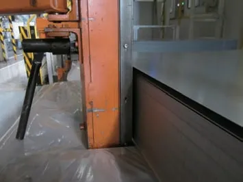
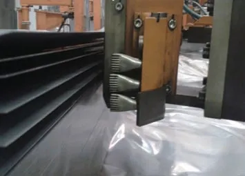
Separation method: Steel sheets use magnetic separation (Figure 1), while aluminum sheets use air blowing separation (Figure 2).
Part transportation: Steel sheets use magnetic belt transportation, aluminum sheets use vacuum belt transportation.
Part position detection: Aluminum sheets use photoelectric detection method.Before steel part production, the surface oil film thickness needs to be checked, while for aluminum part production, the surface dry lubricant thickness needs to be checked. Aluminum sheet materials and steel sheet materials should be produced completely separately, preferably with a dedicated aluminum part production line.
Sheet material transportation
Aluminum is a very sensitive material and is prone to corrosion when in contact with other materials. Before production, the parts of the production line that come into contact with the aluminum sheets (conveyor belts, suction cups, transfer carts, empty work stations, etc.) need to be thoroughly cleaned to avoid iron filings and debris remaining on the aluminum part surface.
Sheet metal repair
The waste disposal systems for aluminum and steel materials must be completely separate. Aluminum powder and chips produced during grinding should be collected and treated centrally, and the grinding workshop needs ventilation; otherwise, it may explode when exposed to open flames in the air.
Aluminum part drawing die
Due to the overall material properties of aluminum sheets, their hardness and strength are far lower than steel sheets. Therefore, the requirements for drawing dies are more stringent during the production and forming process.
To prevent defects such as fuzzing, built-up edges, scratches, and cushion material chips during production, surface treatments like electroplating are applied to the punch and die of the drawing operation, while the surface roughness of the blank holder is reduced.
Design and manufacturing requirements for aluminum part drawing dies:
(1) The minimum R value of the drawing die should be 3 times the material thickness; if it’s too small, it will cause material scraping;
(2) The R angle value of the drawing die must be consistent with the value in the drawing simulation analysis and cannot be arbitrarily changed due to product or other reasons;(3) The draw bead should be disconnected in the scrap knife area to avoid vertical cutting, as shown in Figure 3;
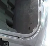
(4) The minimum R values for the punch and die mouth are R8mm and R12mm respectively;
(5) The sheet metal collection line must be controlled to stop about 5mm outside the draw bead;
(6) The flow of the sheet metal should be constrained by the draw bead as much as possible, and the blank holder should not affect the workpiece;
(7) Pay attention to avoid secondary forming, ensuring the workpiece is formed in one stamping operation;
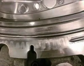
(8) The material’s “flow prevention line” must be consistent with the “drawing prevention line”, and the clearance value between the upper and lower molds of the drawing die should be the material thickness t plus 5% (t+5%). If it’s too large or too small, it’s easy to produce built-up edges (Figure 4).
The springback of aluminum sheets during the forming process is greater than that of steel sheets. Figure 5 shows the strain curves of aluminum alloy, mild steel, and high-strength steel. During the plastic deformation of these three sheet materials, under the same strain conditions, after unloading, the residual stress is released, producing different degrees of springback, with aluminum sheet springback being much greater than steel sheet.
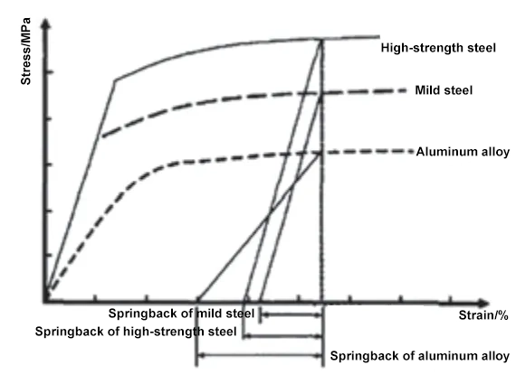
Therefore, in the early stages of aluminum part drawing die process and structural design, while meeting shape and dimension requirements, springback can be constrained by adding process supplements and local draw beads, making the sheet metal forming more complete and balanced during the forming process, thus achieving springback compensation.
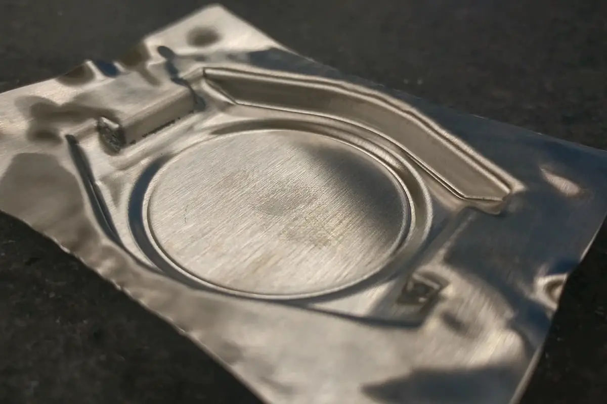
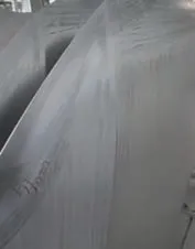
Currently, to enhance the visual impact of new vehicle models, sharp edge designs for exterior covering parts are increasing. However, aluminum sheets are inherently thicker than steel sheets (determined by product design), with stamped aluminum sheets usually thicker than 1mm. For exterior parts, stamped steel sheets are typically 0.7-0.8mm thick. Aluminum sheets are prone to tearing at R corners, so die design requires larger radii (minimum 3 times material thickness), with optimal thinning of 8%-18% for finished parts. Also, aluminum sheets have poor elongation and are easily torn in this area, so aluminum part waistlines cannot achieve the same sharp edges as steel parts, as shown in Figures 6 and 7. This needs to be a key focus during product design.

Aluminum part trimming and piercing dies
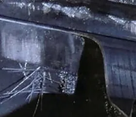
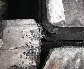
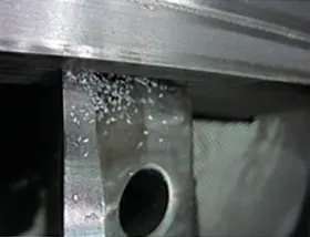
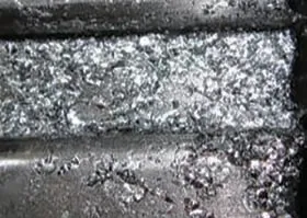
Trimming and piercing operations are the challenging points in aluminum part die adjustment. Due to the much lower hardness of aluminum parts compared to steel parts, trimming aluminum sheets is extremely prone to producing aluminum scrap. Its light weight compared to steel scrap can easily cause negative pressure suction of trimming material and die cavity during high-speed stamping, bringing aluminum scrap into the working surfaces of the punch and die, leading to defects such as indentations, fuzzing, and pitting on the workpiece surface, seriously affecting production efficiency. Common scrap types are generally divided into four categories: strip-shaped, flake-shaped, granular, and powder-shaped, as shown in Figures 8, 9, 10, and 11 respectively.

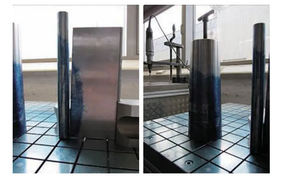
Based on the on-site scrap production situation in trimming and piercing dies, an analysis and statistical comparison of the production locations and causes was conducted, with results shown in Table 1.
Table 1 Analysis results
| Shape | Position of occurrence | Causes |
| Strip | Overlap position of double cutting trimming at the flat blade, obtuse trimming angle greater than 90° | 1. Dull cutting edge due to wear from two trimming overlaps, resulting in rounded corners and poor fit between workpiece and trimming die. |
| Sheet | Upright edge trimming location, areas where the part’s surface shape is irregular, and sharp corners of the part | 2. Excessive trimming clearance producing debris, and compression during vertical edge cutting generating chips. |
| Granular | Root of scrap cutting blade, intersection point of cutting in different directions | 3. Partial chipping of cutting edge causing tearing forces on the sheet metal, producing debris. Height difference at scrap cutting blade leads to tearing and debris formation. |
| Powder | Upright edge trimming location, where the trimming gap is small | 4. Insufficient trimming clearance generating debris, and overly high trimming knife back. |
Production and adjustment requirements for aluminum part trimming and piercing dies:
(1) Trimming edges and trimming inserts need to be quenched, hardness: (58-2)HRC. If the heat treatment form of the trimming insert is adjusted to coating treatment, it needs to be marked as special heat treatment on the detail list of that part.
(2) The cutting edge of the lower die trimming insert should be as sharp as possible.
(3) Trimming inserts for material thicknesses below 1.2mm do not need backing.
(4) The penetration depth of the trimming edge should be about 2-3mm.
(5) Wavy cutting edges are not allowed to avoid pre-cutting phenomena.
(6) The cutting edge of the upper die trimming insert needs to have a -2° negative angle.
(7) The blanking clearance must be accurate, with a single-side clearance of 10%-12% of the material thickness.
(8) The sharpness of the upper and lower die cutting edges for aluminum part dies is more important than for steel part dies.
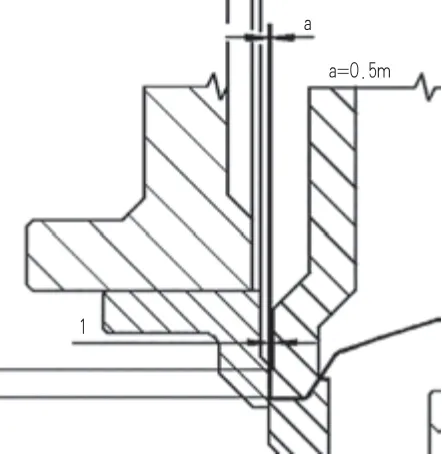
(9) The maximum clearance between the blank holder contour and the trimming line contour is 0.5mm, as shown in Figure 14. Some automotive companies require 0.4-0.8mm, usually set at 0.5mm.
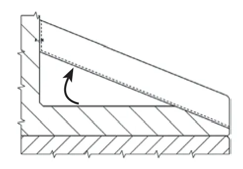
(10) Use textured plates for scrap chutes, with a chute angle not less than 30°, as shown in Figure 15.
(11) The cutting edge coating uses DLC technology, as shown in Figure 16.
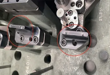
(12) The scrap knife form surface must be consistent with the workpiece/drawing shape, and the lower die scrap knife must also be consistent.
(13) The spring-loaded scrap knife (upper die) must also be consistent with the workpiece shape to prevent tilting and ensure simultaneous cutting.
(14) The upper die insert must not deform the scrap before cutting in.
(15) All punches in aluminum part dies must have ejector pins, with a punch penetration depth of 2-3mm.
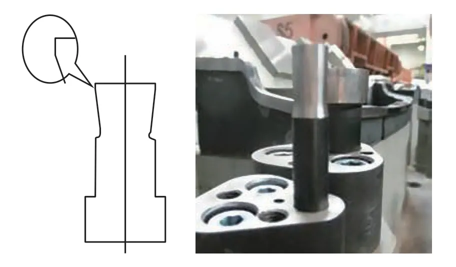
For the same material separation process, there are differences in the maintenance standards for aluminum part punches compared to traditional punches, as shown in Figure 17.
Punches with diameters larger than 6mm are generally processed with a -2° angle to reduce the contact area between the cutting edge and the material.
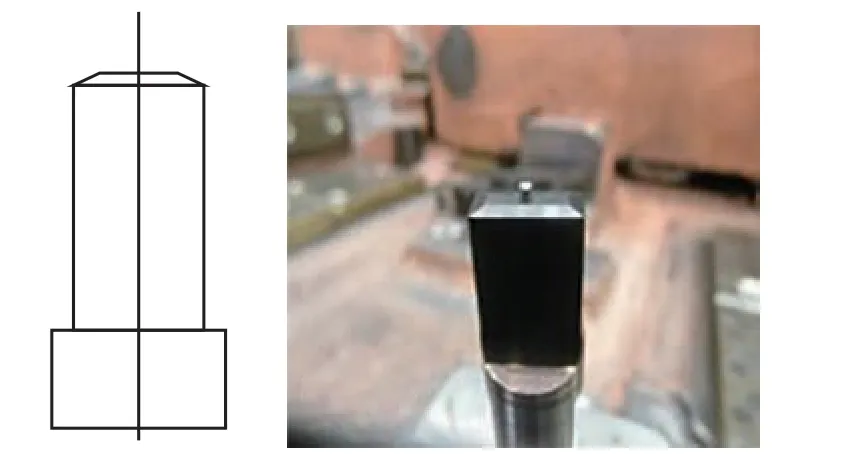
For punches with diameters smaller than 6mm, the cutting edge end face uses a conical end face design and is electroplated to reduce cutting edge friction, as shown in Figure 18.
Aluminum sheet punches must use a structure with ejector pins, with a penetration depth of about 2-3mm to prevent scrap adhesion.
In addition to requirements for blanking clearance and cutting edges, trimming and piercing dies also need to ensure that the R angles in the contact areas between the die cavity and the workpiece are as large as possible to reduce the impact of aluminum scrap on the die during production. This avoids tearing of the aluminum sheet due to overly sharp R angles in the contact area. For the blank holders of trimming and piercing dies, the width of the colored area should be reduced as much as possible while ensuring the workpiece does not deform, as shown in Figure 19. At the same time, non-functional areas should be hollowed out to reduce the probability of scrap cushioning problems during the forming process.

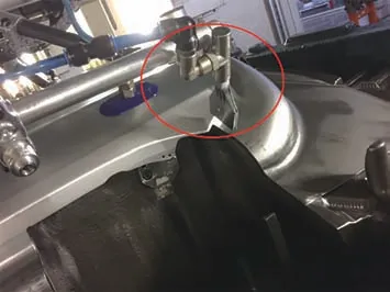
In addition to the die itself, some auxiliary methods can be used to further reduce the impact of scrap on the die. As shown in Figure 20, by using a robotic arm during the workpiece grabbing process, an auxiliary grabbing mechanical hand equipped with a blowing device can use compressed air for high-pressure blowing, forcing scrap into the scrap chute. This prevents scrap from entering the die cavity or being carried into the next process, effectively controlling production stoppages caused by scrap.
Flanging and shaping molds
Flanging and shaping molds are the final forming process, which involves re-constraining the shape and dimensions of the aluminum sheet. During design and debugging, like the drawing process design, it needs to be formed in one step to avoid secondary forming.
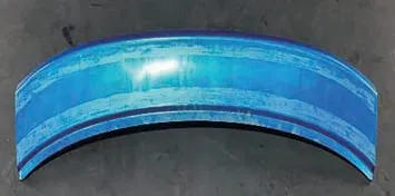
For the flanging pressure plate, to ensure both flanging quality and reduce chip defects, as shown in Figure 21, the colored width should be 20-25mm. Avoid making the pressure area of the flanging pressure plate too wide to reduce the contact area between the mold and the aluminum part. Similar to the trimming and punching process molds, non-functional areas should be hollowed out.
Production and debugging requirements for aluminum part flanging and shaping molds:
(1) Ensure the minimum bending radius of the sheet is 1.5 times the material thickness;
(2) If waves appear during flanging, with the consent of the process and manufacturing departments, it may be necessary to use a pressure plate or clamp for flanging, as shown in Figure 22;
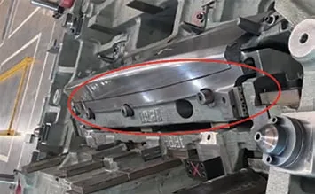
(3) Only consider springback when necessary during flanging or final forming. Depending on the radius and shape of the flange, the springback angle may be greater than the usual 3° (4-5°);
(4) In the forming and flanging areas, the clearance between the punch and die must be normal size + 5% (material thickness + 5%);
(5) Avoid secondary forming; the shape should be formed in one step;
(6) Forming and shearing inserts must be 100% polished and smoothed in the working direction;
(7) Within the allowable size range (rotation diameter <900mm, height <1200mm), flanging inserts need to undergo PVD coating treatment to improve their surface strength and wear resistance.
Conclusion
The trend of aluminum parts gradually replacing steel parts in the automotive industry is inevitable. In the future, as technology continues to mature, including improvements in various mechanical and physical properties of aluminum sheets, the impact on stamping molds may continuously decrease.
However, at the current stage, it is very necessary to master the existing aluminum sheet mold debugging technology and experience. This article elaborates on the control of aluminum chip issues that may be encountered at various stages and processes from blanking to finished products, providing a certain degree of reference for the production and debugging of aluminum part molds in subsequent projects.

