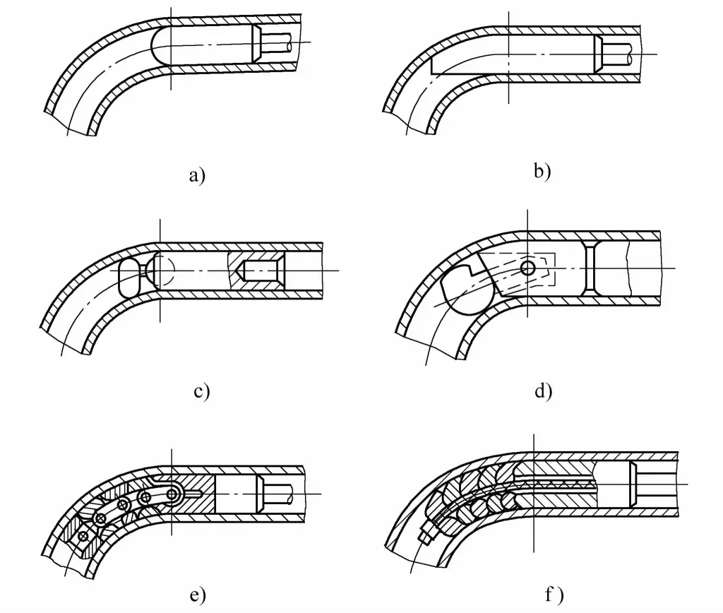
The mandrel is an important part of the core bending device, its role is to support the tube wall from the inside of the tube blank, to prevent the cross-section of the tube from distorting and the tube wall from wrinkling. The so-called core bending is when the tube being bent has a relatively small bending radius R/D or relative wall thickness t/D, in order to obtain high-quality tube parts, a suitable mandrel is inserted inside the tube during the bending process, to prevent flattening and wrinkling at the arc during bending (see Figure 4-36).
For cold bending, it is very necessary to reasonably choose the type of mandrel and master the correct method of use. There are many types of mandrels, generally, mandrels can be divided into two major categories: one is the rigid mandrel (see Figure 4-36a, b), and the other is the flexible mandrel (see Figure 4-36c, d, e, and f).

a) Round head mandrel
b) Spoon-type mandrel
c) Single ball mandrel (socket type)
d) Single ball mandrel (pin type)
e) Multi-ball mandrel (link type)
f) Multi-ball mandrel (flexible shaft type)
The round head mandrel has a simple shape and is easy to manufacture. However, due to the small contact area between the mandrel and the tube wall, the effect of preventing cross-section distortion is poor, usually used for bending of tube parts with low requirements. The mandrel is commonly made of 3Cr2W8V material, with a heat treatment hardness of 52~56HRC.
The spoon-type mandrel has a larger supporting area with the bent outer side wall, which is more effective in preventing cross-sectional distortion than the round-head type mandrel, and it also has a certain anti-wrinkle effect, and is easier to manufacture. It is usually used for smaller diameter bent pipe fittings with a medium wall thickness and a relative bending radius R/D≈2. The material and heat treatment hardness of the mandrel are the same as those of the round-head type mandrel.
The single-ball mandrel (ball socket type, pin type) can rotate a certain amount around the assembly pivot point, can penetrate deeper into the bending deformation zone, and has a better anti-distortion effect, commonly used for bent pipe fittings with a diameter (D≤37mm) not large. The mandrel material is 45 steel (quenched 44~48HRC) or GCr15 (quenched 179~207HBS), if bending stainless steel pipes, aluminum bronze should be used to manufacture the mandrel.
The chain-type multi-ball mandrel is composed of supporting balls and links, and can only swing within a single bending plane. Since it can penetrate deep into the bending deformation zone and bend together with the billet, it has a good effect in preventing cross-sectional distortion.
The flexible shaft multi-ball mandrel is made by stringing multiple bowl-shaped spheres with a flexible shaft, which can swing in any direction in space, suitable for thin-walled pipe fittings of single, multiple, and spatial bending forming.
When bending pipes with a multi-ball mandrel, the mandrel can also be used to straighten the pipe fittings during the process of being pulled out by the hydraulic cylinder after bending. The main disadvantage of the multi-ball mandrel is that it is troublesome to manufacture, and the material and heat treatment requirements of the mandrel are the same as those of the single-ball mandrel.
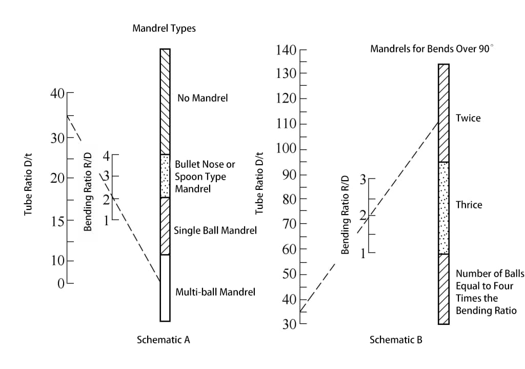
For different bending processes, different types of mandrels should be used. For press bending and wrap bending, rigid mandrels are mostly used, and the head of the mandrel is hemispherical or other curved shapes. Whether a mandrel is needed for bending, and what kind of mandrel to use, can be determined by Figure 4-37.

For pipes with the same outer diameter D and wall thickness t, when bending different arc radii R, due to the different relative bending radius R/D, relative wall thickness t/D, and bending angle α, the choice of core-piercing method is shown in Table 4-9.
Table 4-9 Mandrel piercing method
| Relative wall thickness t/D | Relative curvature radius R/D | |||||||||
| 1 | 1.5 | 2 | 2.5 | 3 | ||||||
| 90° | 180° | 90° | 180° | 90° | 180° | 90° | 180° | 90° | 180° | |
| 0.1 | H | H | H | H | H | H | H | H | N | N |
| 0.05 | H | H | H | H | H | H | H | H | N | N |
| 1/3 | F-2 | F-3 | F-2 | F-3 | F-2 | F-2 | F-3 | F-2 | H | H |
| 0.025 | F-3 | F-3 | F-3 | F-3 | F-3 | F-3 | F-2 | F-2 | H | H |
| 0.02 | F-3 | F-4 | F-3 | F-4 | F-2 | F-3 | F-2 | F-3 | F-2 | F-2 |
| 1/6 | F-4 | F-5 | F-4 | F-5 | F-3 | F-4 | F-3 | F-4 | F-2 | F-3 |
| 1/7 | F-4 | F-5 | F-4 | F-5 | F-3 | F-4 | F-3 | F-4 | F-3 | F-4 |
Note:
- The table shows the maximum bending angles α of 90° and 180°.
- N indicates that the use of a mandrel is not required (i.e., mandrel-less bending).
- H indicates that hard mandrel bending can be used.
- F indicates that soft mandrel bending is required, with the number following indicating the recommended number of soft mandrel sections.
After determining the shape of the mandrel, it still cannot guarantee the bending of high-quality tubes. The gap size between the mandrel and the inner diameter of the tube is also an important factor affecting the quality of the bending. If the diameter of the mandrel’s ball joint is too small, the inside of the tube may form wave-like wrinkles when bending, and it may also fail to prevent the outside of the arc from flattening; if the diameter is too large or the outer diameter of the ball joint is not smooth enough, it may damage the tube wall, and the outside of the tube arc may bulge or even burst.
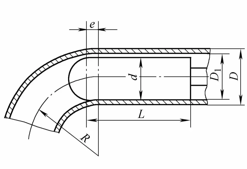
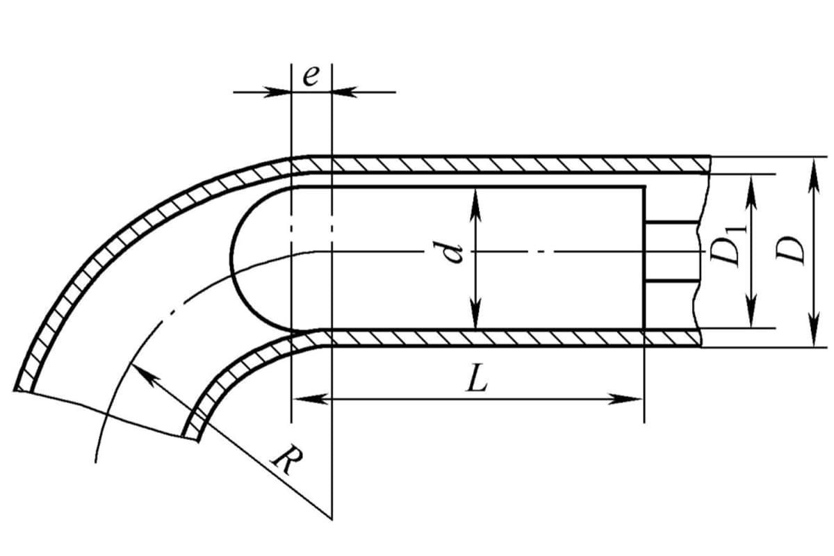
Choosing a reasonable mandrel diameter and ensuring it is sufficiently lubricated are indispensable elements for ensuring the quality of tube bending. The size of the round-head mandrel and its working position inside the tube are shown in Figure 4-38.

To smoothly insert the mandrel into the tube blank, the diameter d of the mandrel should generally be 0.5~1.5mm smaller than the inner diameter of the tube blank, namely
d = D 1 – (0.5 ~ 1.5)
The cylindrical length L of the mandrel is
L = (3 ~ 5)d
When the diameter d of the mandrel is large, take a smaller value, otherwise take a larger value.
The working position of the mandrel should be a certain distance e ahead of the bending centerline. However, the lead distance should not be too much, as excessive lead can cause severe stretching on the outer wall of the tube blank during bending, increasing the thinning amount and easily leading to rupture. If the mandrel is positioned too far back, the inner wall of the tube blank may become unstable and wrinkle during bending, severely distorting the cross-section and failing to perform the intended function of the mandrel.
Generally speaking, the size of e should be determined based on the billet diameter, bending radius, and the gap size between the billet inner diameter and the mandrel, and then adjusted appropriately according to the actual production situation. The value of e can be calculated by the following formula
Where
- D 1 is the billet inner diameter (mm);
- R is the central layer bending radius (mm);
- z is the gap between the billet inner wall and the mandrel (mm), z=D 1 -d.

